Table of contents
1. Algorithm simulation effect
2. Algorithms involve an overview of theoretical knowledge
2.2. Principle of VV algorithm
4. Complete algorithm code file
1. Algorithm simulation effect
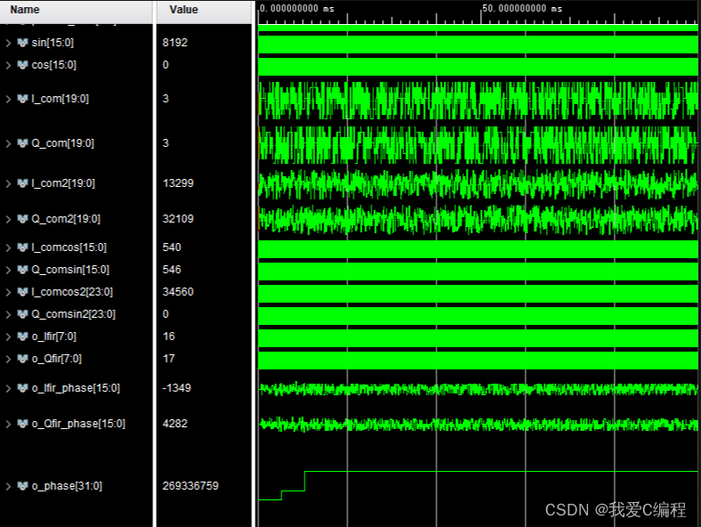
This system has been developed on the Vivado2019.2 platform, and the Vivado2019.2 simulation results are as follows:
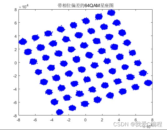
Import the FPGA simulation results into matlab and display the constellation diagram, the results are as follows:

2. Algorithms involve an overview of theoretical knowledge
In modern communication systems, modulation technology is an important means to achieve high-speed data transmission and optimize spectrum efficiency. Among them, the 64QAM modulation technology is a common high-order modulation technology, which can realize the transmission of 6-bit information per symbol, thereby increasing the data transmission rate. However, in practical applications, modulated signals are often affected by various interferences and distortions, resulting in increased transmission error rates. Therefore, phase estimation and compensation technology is one of the key links in demodulation and recovery of modulated signals. A VV algorithm for phase estimation and compensation of 64QAM modulated signal with phase deviation is introduced, and its realization steps and mathematical principles are explained in detail.
2.1. Basic principles
In 64QAM modulation, each symbol can be expressed as a linear superposition of 4 baseband signals, namely:
$$ s_k = I_k + jQ_k = \sum_{n=0}^3 a_{kn}\cdot e^{j\theta_{kn}},\ \ \ \ \ k=0,1,...,N-1 $$
Among them, I_k and Q_k represent the real part and imaginary part of the $k$ symbol, respectively, and a_{kn} and \theta_{kn} represent the amplitude and phase of the nth baseband signal of the kth symbol, respectively. j is the imaginary unit.
Ideally, the phase of the modulated signal is continuous and smooth, but in practical applications, the modulated signal is often affected by various disturbances and distortions, resulting in phase deviation. Therefore, it is necessary to perform phase estimation and compensation on the received modulated signal to realize signal demodulation and recovery. The basic idea of phase estimation and compensation is to use the known signal structure and characteristics, calculate and compare the phase difference between the received signal and the ideal signal, obtain the phase deviation, and perform phase correction on the received signal. In the 64QAM modulation signal with phase deviation, VV algorithm can be used to realize phase estimation and compensation.
2.2. Principle of VV algorithm
The VV algorithm is a phase estimation and compensation algorithm based on vector rotation. Its basic idea is to convert the received signal into a vector form, and rotate and scale the vector to achieve phase correction. The implementation steps of the VV algorithm are as follows:
In the VV algorithm, a reference signal needs to be selected as the ideal signal. Generally, known signal subcarriers or pilot symbols can be selected as reference signals. Suppose the reference signal is s_{ref}.
Express the received symbol $s_k$ and reference signal $s_{ref}$ in vector form:
$$ \mathbf{s}k = \left[\begin{matrix} I_k \ Q_k \end{matrix}\right],\ \ \ \ \ \mathbf{s}{ref} = \left[\begin{matrix} I_{ref} \ Q_{ref} \end{matrix}\right] $$
Vector rotation
calculates the phase difference $\Delta\theta$ between the received signal and the reference signal:
$$ \Delta\theta = \text{angle}(\mathbf{s}k) - \text{angle}(\mathbf{s}{ref}) $$
Among them, $\text{angle}(\cdot)$ represents the phase angle of the vector. According to Euler's formula, vector rotation can be expressed as:
$$ \mathbf{s}_k^{'} = \mathbf{s}_k e^{-j\Delta\theta} $$
Among them, $\mathbf{s}_k^{'}$ represents the received signal after phase rotation.
Vector Scaling
In order to eliminate the phase deviation, the rotated received signal needs to be scaled. According to the modulus length formula after vector rotation, we can get:
$$ \left|\mathbf{s}_k^{'}\right| = \left|\mathbf{s}_k\right| $$
Therefore, the rotated received signal can be scaled as:
$$ \mathbf{s}_k^{''} = \frac{\mathbf{s}_k^{'}}{\left|\mathbf{s}_k^{'}\right|} \cdot \left |\mathbf{s}_k\right| $$
Phase smoothing
In order to eliminate the jitter of phase deviation, it is necessary to smooth the phase. In general, the phase can be smoothed using a low-pass filter or a moving average filter. Assuming that the filter output is $\Delta\hat{\theta}$, the symbol after phase estimation and compensation can be obtained as:
$$ \hat{s}_k = \left|\mathbf{s}_k^{''}\right| \cdot e^{j(\text{angle}(\mathbf{s}_k^{''})+\delta\hat{\theta})} $$
In the implementation of the above-mentioned VV algorithm, operations such as vector rotation and scaling are involved, and complex number operations and Euler's formula are required. Some relevant mathematical principles will be introduced below.
Complex numbers can be represented as a linear combination of real and imaginary parts, namely:
$$ z = a + jb $$
Among them, $a$ and $b$ are the real part and imaginary part respectively, and $j$ is the imaginary unit. Complex addition, subtraction, and multiplication can be expressed as:
$$ (a_1+jb_1) + (a_2+jb_2) = (a_1+a_2) + j(b_1+b_2) $$$$ (a_1+jb_1) - (a_2+jb_2) = (a_1-a_2) + j(b_1-b_2) $$$$ (a_1+jb_1)\cdot(a_2+jb_2) = (a_1a_2-b_1b_2) + j(a_1b_2+a_2b_1) $$
Complex number division can be expressed as:
$$ \frac{a_1+jb_1}{a_2+jb_2} = \frac{(a_1a_2+b_1b_2)+j(b_1a_2-a_1b_2)}{a_2^2+b_2^2} $$
Euler's formula
Euler's formula is a formula that expresses exponential functions as trigonometric functions, which can be expressed as:
$$ e^{j\theta} = \cos\theta + j\sin\theta $$
Among them, $\theta$ is the angle. Euler's formula can be used to represent complex numbers in terms of magnitude and phase, namely:
$$ z = |z|e^{j\theta} $$
Among them, $|z|$ is the modulus length of the complex $z$, and $\theta$ is the phase angle of the complex $z$.
Vector rotation
In the VV algorithm, it is necessary to perform vector rotation on the received signal to correct the phase deviation. A vector rotation can be expressed as:
$$ \mathbf{s}_k^{'} = \mathbf{s}_k e^{-j\Delta\theta} $$
Among them, $\mathbf{s}_k$ is the vector form of the received signal, and $\Delta\theta$ is the phase difference between the received signal and the reference signal. A vector rotation can be expressed using Euler's formula and complex arithmetic as:
$$ \mathbf{s}_k^{'} = |\mathbf{s}_k|e^{j(\text{angle}(\mathbf{s}_k)-\Delta\theta)} $$
Vector scaling
In the VV algorithm, the rotated received signal needs to be scaled to eliminate phase deviation. Vector scaling can be expressed as:
$$ \mathbf{s}_k^{''} = \frac{\mathbf{s}_k^{'}}{\left|\mathbf{s}_k^{'}\right|} \cdot \left |\mathbf{s}_k\right| $$
Among them, $\mathbf{s}_k^{'}$ is the vector form of the rotated received signal, $\left|\mathbf{s}_k^{'}\right|$ is $\mathbf{s}_k The modulus length of ^{'}$, $\left|\mathbf{s}_k\right|$ is the modulus length of the received signal $\mathbf{s}_k$. Vector scaling can be expressed using Euler's formula and complex arithmetic as:
$$ \mathbf{s}_k^{''} = |\mathbf{s}_k|e^{j(\text{angle}(\mathbf{s}_k)-\Delta\theta)} $$
Among them, $\text{angle}(\mathbf{s}_k)$ is the phase angle of the received signal $\mathbf{s}_k$.
Phase smoothing
In the VV algorithm, in order to eliminate the jitter of the phase deviation, the phase needs to be smoothed. In general, the phase can be smoothed using a low-pass filter or a moving average filter. Assuming that the filter output is $\Delta\hat{\theta}$, the symbol after phase estimation and compensation can be obtained as:
$$ \hat{s}_k = \left|\mathbf{s}_k^{''}\right| \cdot e^{j(\text{angle}(\mathbf{s}_k^{''})+\delta\hat{\theta})} $$
Among them, $\mathbf{s}_k^{''}$ is the vector form of the scaled received signal, $\left|\mathbf{s}_k^{''}\right|$ is $\mathbf{s The modulus length of }_k^{''}$, $\text{angle}(\mathbf{s}_k^{''})$ is the phase angle of $\mathbf{s}_k^{''}$.
In this way, the realization of phase estimation and compensation of 64QAM modulated signal with phase deviation is completed.
3. Verilog core program
...........................................................................
module TEST;

	reg clk;
	reg rst;
	reg start;

    wire  [5:0] parallel_data;
    wire [15:0]sin;
    wire [15:0]cos;
	wire signed[19:0]  I_com;
	wire signed[19:0]  Q_com;
	wire signed[19:0]  I_com2;
	wire signed[19:0]  Q_com2;
    wire signed[15:0]I_comcos;
    wire signed[15:0]Q_comsin;


	// DUT
	tops_64QAM_mod  top(
	   .clk(clk),
	   .rst(rst),
	   .start(start),
	   .parallel_data(parallel_data),
	   .sin(sin),
	   .cos(cos),
	   .I_com(I_com),
	   .Q_com(Q_com),
	   .I_com2(I_com2),
	   .Q_com2(Q_com2),
	   .I_comcos(I_comcos),
	   .Q_comsin(Q_comsin)
	   );


wire signed[23:0]I_comcos2;
wire signed[23:0]Q_comsin2;
wire signed[7:0]o_Ifir;
wire signed[7:0]o_Qfir;
wire signed[15:0]o_Ifir_phase;
wire signed[15:0]o_Qfir_phase;
wire signed[31:0]o_phase;
tops_64QAM_phase_est  top2(
	   .clk(clk),
	   .rst(rst),
	   .start(start),
	   .I_comcos(I_comcos),
	   .Q_comsin(Q_comsin),
	   .I_comcos2(I_comcos2),
	   .Q_comsin2(Q_comsin2),
	   .o_Ifir(o_Ifir),
	   .o_Qfir(o_Qfir),
	   .o_I_phase(o_Ifir_phase),
	   .o_Q_phase(o_Qfir_phase),
	   .o_phase(o_phase)
	   );


	initial begin
		clk = 0;
		rst = 0;
		start = 1;
		#10;
		rst = 1;
	end

	always #5
	clk <= ~clk;


reg writeen;
initial
begin
    writeen = 1'b0;
    #150000
    writeen = 1'b1;
end

reg[4:0]divcnt;
always @(posedge clk or negedge rst)
begin
     if(~rst)
	  begin
	  divcnt<={5{1'b0}};
	  end
else begin
	  divcnt<=divcnt+{5{1'b1}};
     end
end


integer fout1;
integer fout2;
initial begin
 fout1 = $fopen("It.txt","w");
 fout2 = $fopen("Qt.txt","w");
end

always @ (posedge divcnt[4])
 begin
     if(writeen==1)
     begin
   	 $fwrite(fout1,"%d\n",I_com2);
	 $fwrite(fout2,"%d\n",Q_com2);
	 end
end


integer fout3;
integer fout4;
initial begin
 fout3 = $fopen("IR.txt","w");
 fout4 = $fopen("QR.txt","w");
end

always @ (posedge divcnt[4])
 begin
     if(writeen==1)
     begin
   	 $fwrite(fout3,"%d\n",o_Ifir_phase);
	 $fwrite(fout4,"%d\n",o_Qfir_phase);
	 end
end


endmodule
00_022m
4. Complete algorithm code file
V