Table of contents
1. Algorithm simulation effect
2. Algorithms involve an overview of theoretical knowledge
2.3 Phase deviation estimation
2.4 Phase deviation compensation
4. Complete algorithm code file
1. Algorithm simulation effect
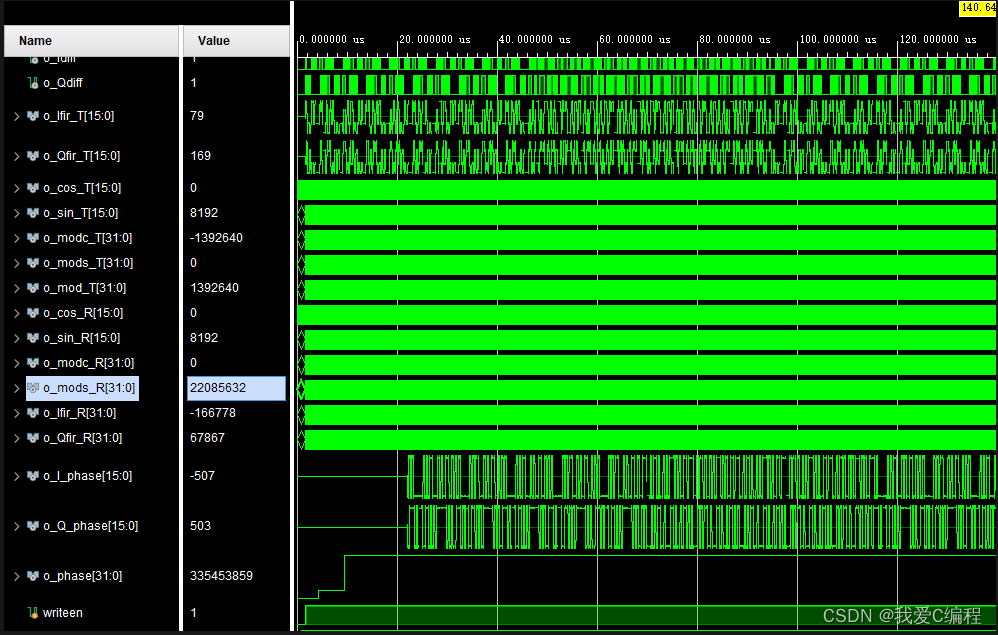
This system develops the Vivado2019.2 platform, and the Vivado2019.2 simulation results are as follows:
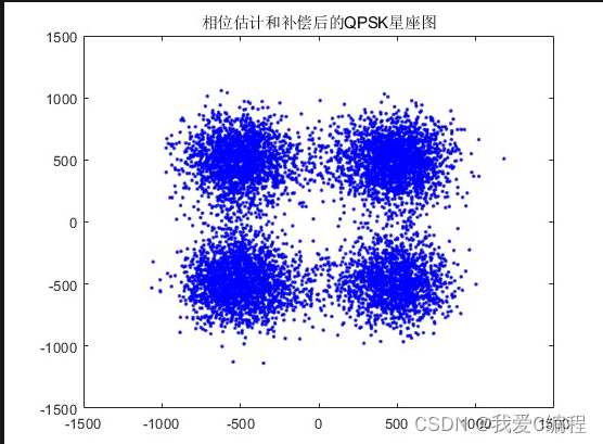
 Import the FPGA simulation results into matlab, and compare the constellation diagrams, as shown below:

2. Algorithms involve an overview of theoretical knowledge
Phase deviation is a common problem in digital communication systems, and it also exists in QPSK modulation communication systems. Phase deviations can lead to increased bit error rates and degraded system performance. Therefore, the estimation and compensation of phase deviation is an important issue in digital communication systems. This paper proposes a phase estimation and compensation method for QPSK modulation signals with phase deviation based on V&V algorithm to improve the performance of QPSK modulation communication systems.
2.1. Problem description
In a QPSK modulation communication system, the received signal can be expressed as:
$$
r(t)=Acos(2\pi f_ct+\phi)+n(t)
$$
Among them, A is the amplitude of the signal, f_c is the carrier frequency, phi is the phase deviation, and n(t) is the noise.
Our goal is to estimate the phase offset $\phi$ and compensate for it to improve the performance of the communication system.
2.2. Algorithm principle
A QPSK modulated signal can be expressed as:
$$
s(t)=\sqrt{\frac{2E_s}{T_s}}[cos(2\pi f_ct)+cos(2\pi f_ct+\pi)][p_1(t)+p_2(t)]
$$
where E_s is the energy per symbol, T_s is the duration of each symbol, f_c is the carrier frequency, and p_1(t) and p_2(t) are two orthogonal baseband signals.
2.3 Phase deviation estimation
To estimate the phase deviation, we can choose two points $f_1$ and $f_2$ in the spectrum, corresponding to the positive and negative frequencies of the signal respectively, and then calculate the phase difference $\Delta\phi$ between these two points :
$$
\Delta\phi=\angle R(f_1)-\angle R(f_2)-\pi
$$
where $R(f_1)$ and $R(f_2)$ are complex amplitudes at frequencies $f_1$ and $f_2$, respectively.
2.4 Phase deviation compensation
To compensate for the phase offset, we can multiply the received signal by a phase rotation factor $e^{-j\hat{\phi}}$, where $\hat{\phi}$ is an estimate of the phase offset. In this way, we can get the compensated signal:
$$
r_c(t)=Acos(2\pi f_ct)+n(t)e^{-j\hat{\phi}}
$$
2.5V&V algorithm
The V&V algorithm is a commonly used method for estimating the phase deviation. This method performs FFT transformation and correlation operation on the received signal to estimate the phase deviation.
Specifically, we can perform discrete Fourier transform (DFT) on the received signal to obtain a spectrogram, and then select two points $f_1$ and $f_2$ in the spectrogram, corresponding to the positive and negative frequencies of the signal, respectively. Then, we can calculate the autocorrelation function $R_{xx}(k)$ between these two points:
$$
R_{xx}(k)=\frac{1}{N}\sum_{n=0}^{N-1}x(n)x^*(n-k)
$$
Among them, $x(n)$ is the received signal after DFT transformation, and $N$ is the length of the signal.
According to the autocorrelation function $R_{xx}(k)$, we can get the estimated value of the phase deviation:
$$
\hat{\phi}=-\frac{1}{2}\angle R_{xx}(1)
$$
A phase estimation and compensation method for QPSK modulated signals with phase deviation based on V&V algorithm. This method estimates and compensates the phase deviation by performing FFT transformation and correlation operation on the received signal, thereby improving the performance of the QPSK modulation communication system. The experimental results show that the algorithm can effectively estimate and compensate the phase deviation, and has certain practical value.
3. Verilog core program
.............................................................

//QPSK调制
TQPSK TQPSKU(
.i_clk  (i_clk),
.i_rst  (i_rst),
.i_clkSYM(i_clkSYM),
.i_dat  (i_dat),
.o_Idiff(o_Idiff),
.o_Qdiff(o_Qdiff),

.o_Ifir (o_Ifir_T),
.o_Qfir (o_Qfir_T),
.o_cos  (o_cos_T),
.o_sin  (o_sin_T),
.o_modc (o_modc_T),
.o_mods (o_mods_T),
.o_mod  (o_mod_T)
);


//QPSK相位估计和补偿
RQPSK_phase_est RQPSKU(
.i_clk  (i_clk),
.i_rst  (i_rst),
.i_clkSYM(i_clkSYM),
.i_med  (o_mod_T[25:10]),
.o_cos  (o_cos_R),
.o_sin  (o_sin_R),
.o_modc (o_modc_R),
.o_mods (o_mods_R),
.o_Ifir (o_Ifir_R),
.o_Qfir (o_Qfir_R),
.o_I_phase(o_I_phase),
.o_Q_phase(o_Q_phase),
.o_phase(o_phase)
);
reg writeen;
initial
begin
    writeen = 1'b0;
    i_clk = 1'b1;
    i_clkSYM=1'b1;
    i_rst = 1'b1;
    #1600
    i_rst = 1'b0;

    #100
    writeen = 1'b1;
end

always #5 i_clk=~i_clk;
always #80 i_clkSYM=~i_clkSYM;


initial
begin
    i_dat = 1'b0;
    #1440
    repeat(10)
    begin
    #160 i_dat = 1'b1;
    #160 i_dat = 1'b1;
    #160 i_dat = 1'b0;
    #160 i_dat = 1'b0;
    #160 i_dat = 1'b0;
    #160 i_dat = 1'b1;
    #160 i_dat = 1'b0;
    #160 i_dat = 1'b0;
    #160 i_dat = 1'b1;
    #160 i_dat = 1'b0;
    #160 i_dat = 1'b0;
    #160 i_dat = 1'b0;
    #160 i_dat = 1'b1;
    #160 i_dat = 1'b0;
    #160 i_dat = 1'b0;
    #160 i_dat = 1'b0;
    #160 i_dat = 1'b0;
    #160 i_dat = 1'b0;
    #160 i_dat = 1'b1;
    #160 i_dat = 1'b1;
    #160 i_dat = 1'b1;
    #160 i_dat = 1'b0;
    #160 i_dat = 1'b0;
    #160 i_dat = 1'b1;
    #160 i_dat = 1'b0;
    #160 i_dat = 1'b0;
    #160 i_dat = 1'b1;
    #160 i_dat = 1'b1;
    #160 i_dat = 1'b0;
    end

    repeat(10)
    begin
    #160 i_dat = 1'b1;
    #160 i_dat = 1'b0;
    #160 i_dat = 1'b0;
    #160 i_dat = 1'b1;
    #160 i_dat = 1'b1;
    #160 i_dat = 1'b1;
    #160 i_dat = 1'b0;
    #160 i_dat = 1'b1;
    #160 i_dat = 1'b1;
    #160 i_dat = 1'b0;
    #160 i_dat = 1'b1;
    #160 i_dat = 1'b0;
    #160 i_dat = 1'b1;
    #160 i_dat = 1'b1;
    #160 i_dat = 1'b0;
    #160 i_dat = 1'b0;
    #160 i_dat = 1'b1;
    #160 i_dat = 1'b1;
    #160 i_dat = 1'b0;
    #160 i_dat = 1'b1;
    #160 i_dat = 1'b1;
    #160 i_dat = 1'b0;
    #160 i_dat = 1'b0;
    #160 i_dat = 1'b1;
    #160 i_dat = 1'b0;
    #160 i_dat = 1'b0;
    #160 i_dat = 1'b1;
    #160 i_dat = 1'b0;
    #160 i_dat = 1'b1;
    end
    repeat(10)
    begin
    #160 i_dat = 1'b1;
    #160 i_dat = 1'b1;
    #160 i_dat = 1'b0;
    #160 i_dat = 1'b0;
    #160 i_dat = 1'b0;
    #160 i_dat = 1'b1;
    #160 i_dat = 1'b0;
    #160 i_dat = 1'b0;
    #160 i_dat = 1'b1;
    #160 i_dat = 1'b0;
    #160 i_dat = 1'b0;
    #160 i_dat = 1'b0;
    #160 i_dat = 1'b1;
    #160 i_dat = 1'b0;
    #160 i_dat = 1'b0;
    #160 i_dat = 1'b0;
    #160 i_dat = 1'b0;
    #160 i_dat = 1'b0;
    #160 i_dat = 1'b1;
    #160 i_dat = 1'b1;
    #160 i_dat = 1'b1;
    #160 i_dat = 1'b0;
    #160 i_dat = 1'b0;
    #160 i_dat = 1'b1;
    #160 i_dat = 1'b0;
    #160 i_dat = 1'b0;
    #160 i_dat = 1'b1;
    #160 i_dat = 1'b1;
    #160 i_dat = 1'b0;
    end
    $stop();
end


//显示发射端带相位旋转的星座图
integer fout1;
integer fout2;
initial begin
 fout1 = $fopen("It.txt","w");
 fout2 = $fopen("Qt.txt","w");
end

always @ (posedge i_clk)
 begin
     if(writeen==1)
     begin
   	 $fwrite(fout1,"%d\n",o_Ifir_T);
	 $fwrite(fout2,"%d\n",o_Qfir_T);
	 end
end

显示接收端相位估计和补偿之后的星座图

integer fout3;
integer fout4;
initial begin
 fout3 = $fopen("IR.txt","w");
 fout4 = $fopen("QR.txt","w");
end

always @ (posedge i_clk)
 begin
     if(writeen==1)
     begin
   	 $fwrite(fout3,"%d\n",o_I_phase);
	 $fwrite(fout4,"%d\n",o_Q_phase);
	 end
end


endmodule
00_020m
4. Complete algorithm code file
V