Article Directory
I2C bus
- I2C is a synchronous serial half-duplex bus
- The I2C bus is a simple, two-way two-wire synchronous serial bus developed by Philips. It only needs two wires to transfer information between devices connected to the bus.
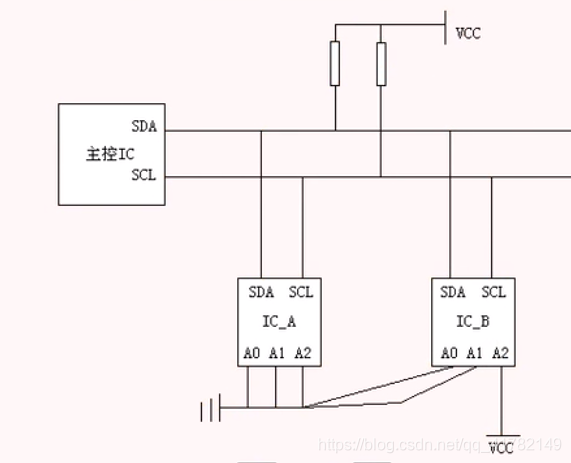
- I2C communication only needs two bidirectional buses- a data line SDA (serial data: serial data line), a clock line SCL (serial clock: serial clock line). The SDA line is used to transmit data, and the SCL line is used to synchronize data transmission and reception . The data transmitted by the SDA line is big-endian transmission (the high byte of the byte is transmitted first), and each transmission is 8 bits, that is, 1 byte. Support multi-mastering, there can only be one master at any time. Each device connected to the bus has an independent address addr, a total of 7 bits, and the host uses this address to access the device. Both SDA and SCL buses need to be connected with pull-up resistors . When the bus is free, both lines are high. Any device connected to the bus will pull the bus signal low when it outputs a low level, that is, the SDA and SCL of each device are in a line-and relationship. When multiple hosts use the bus at the same time, arbitration is needed to determine which device occupies the bus, otherwise the data will conflict . (As shown below) The

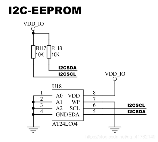
following is the schematic diagram of the Mini6410 I2C chip circuit
I2C protocol
-
I2C does not refer to a software-defined protocol, but a hardware specification
-
In the idle state, both
SDA and SCL signal lines are at high level, that is, all devices on the bus release the bus, and the respective pull-up resistors of the two signal lines pull the level high; -
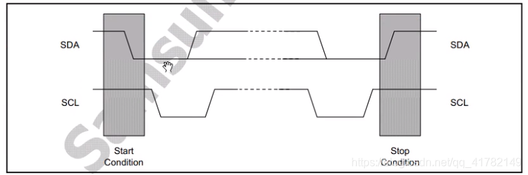
. Start and end signals
start signal : the SCL is high, the SDA transitions from high to low, the data transfer begins. The start signal is generated by the main controller .
End signal : When SCL is high level, SDA jumps from low level to high level, ending the data transmission. The end signal can only be generated by the main controller .
-
When the data transmission
SCL is low, SDA can jump; when
SCL is high, SDA must be kept
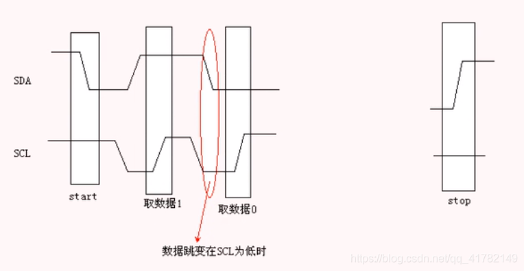
-
Acknowledge signal ACK
I2C bus data is transmitted in bytes (8 bits). After the sending device sends a byte, the data bus is released during the 9th pulse of the clock, and the receiver sends an ACK (to The level of the data bus is pulled low) to indicate that the data is successfully received. -
No response signal NACK
during the 9th pulse of the clock, the transmitter releases the data bus, and the receiver does not pull down the data bus to indicate a NACK. NACK has two purposes:
a. Generally, it indicates that the receiver has not successfully received data bytes;
b. When the receiver is the master, after it receives the last byte, it should send a NACK signal to notify the controlled transmitter to end data transmission and release the bus so that the master receiver sends a stop signal STOP. -
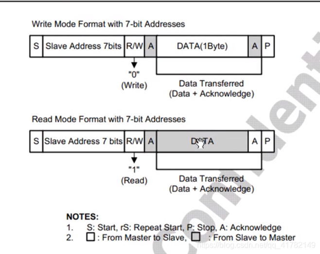
I2C protocol format
I2C protocol format (as shown below)
I2C chip address determination
- Chip address 7 bits or 10 bits
- Chip address format: chip ID + hardware engineer determined ID (CHIPID + VarID) , but it will limit the number of chips of the same manufacturer used
- For the I2C chip (AT24LC04) used by Mini6410, the address of the I2C chip is 0x50

- Similar I2C chip address hardware design
For related documents about I2C registers, please refer to the chapter IIC in the user manual of S3C6410. If you want to understand the operation of IIC, you need to configure related registers.
Link: https://pan.baidu.com/s/1waTxUGk7yOq67Whw-yrL4Q
Extraction code: krvz
This blog is just a brief introduction to the I2C bus and protocol. It can be regarded as a popularization. The use and operation of IIC under Linux requires in-depth systematic learning. Follow-up blogs will be updated, a long way! ! !