本章介绍一种在游戏和应用中,模拟动态阴影的基本阴影贴图算法;还有一些更复杂和效果更好的阴影算法,比如cascading shadow maps[Engel06],都是基于基本阴影算法扩展出来的。
学习目标
- 熟悉基本阴影贴图算法;
- 学习投射纹理如何工作;
- 找到正交投射;
- 理解阴影贴图锯齿问题和一些常用的修复它们的策略。
1 渲染场景深度
阴影贴图算法依赖于从灯光的视角渲染场景的深度(渲染到纹理)。渲染完深度后,我们知道了距离灯光最近的像素片段(这些像素片段不会在阴影中)。我们实现一个ShadowMap类来帮助我们保存灯光透视视角的场景深度。它简单的封装了一个深度/模板缓冲,需要的views,和viewport。
class ShadowMap
{
public:
	ShadowMap(ID3D12Device* device, UINT width, UINT height);
	ShadowMap(const ShadowMap& rhs)=delete;
	ShadowMap& operator=(const ShadowMap& rhs)=delete;
	˜ShadowMap()=default;

	UINT Width()const;
	UINT Height()const;

	ID3D12Resource* Resource();
	CD3DX12_GPU_DESCRIPTOR_HANDLE Srv()const;
	CD3DX12_CPU_DESCRIPTOR_HANDLE Dsv()const;

	D3D12_VIEWPORT Viewport()const;
	D3D12_RECT ScissorRect()const;

	void BuildDescriptors(
		CD3DX12_CPU_DESCRIPTOR_HANDLE hCpuSrv,
		CD3DX12_GPU_DESCRIPTOR_HANDLE hGpuSrv,
		CD3DX12_CPU_DESCRIPTOR_HANDLE hCpuDsv);

	void OnResize(UINT newWidth, UINT newHeight);

private:
	void BuildDescriptors();
	void BuildResource();

private:
	ID3D12Device* md3dDevice = nullptr;
	D3D12_VIEWPORT mViewport;
	D3D12_RECT mScissorRect;
	UINT mWidth = 0;
	UINT mHeight = 0;
	DXGI_FORMAT mFormat = DXGI_FORMAT_R24G8_TYPELESS;
	CD3DX12_CPU_DESCRIPTOR_HANDLE mhCpuSrv;
	CD3DX12_GPU_DESCRIPTOR_HANDLE mhGpuSrv;
	CD3DX12_CPU_DESCRIPTOR_HANDLE mhCpuDsv;
	Microsoft::WRL::ComPtr<ID3D12Resource> mShadowMap = nullptr;
};
构造函数通过分辨率和viewport来创建纹理。分辨率影响了阴影的效果,高分辨率会需要更多性能开销和内存。
ShadowMap::ShadowMap(ID3D12Device* device, UINT width, UINT height)
{
	md3dDevice = device;
	mWidth = width;
	mHeight = height;
	mViewport = { 0.0f, 0.0f, (float)width, (float)height, 0.0f, 1.0f };
	mScissorRect = { 0, 0, (int)width, (int)height };

	BuildResource();
}

void ShadowMap::BuildResource()
{
	D3D12_RESOURCE_DESC texDesc;
	ZeroMemory(&texDesc, sizeof(D3D12_RESOURCE_DESC));
	texDesc.Dimension = D3D12_RESOURCE_DIMENSION_TEXTURE2D;
	texDesc.Alignment = 0;
	texDesc.Width = mWidth;
	texDesc.Height = mHeight;
	texDesc.DepthOrArraySize = 1;
	texDesc.MipLevels = 1;
	texDesc.Format = mFormat;
	texDesc.SampleDesc.Count = 1;
	texDesc.SampleDesc.Quality = 0;
	texDesc.Layout = D3D12_TEXTURE_LAYOUT_UNKNOWN;
	texDesc.Flags = D3D12_RESOURCE_FLAG_ALLOW_DEPTH_STENCIL;

	D3D12_CLEAR_VALUE optClear;
	optClear.Format = DXGI_FORMAT_D24_UNORM_S8_UINT;
	optClear.DepthStencil.Depth = 1.0f;
	optClear.DepthStencil.Stencil = 0;
	ThrowIfFailed(md3dDevice->CreateCommittedResource(
		&CD3DX12_HEAP_PROPERTIES(D3D12_HEAP_TYPE_DEFAULT),
		D3D12_HEAP_FLAG_NONE,
		&texDesc,
		D3D12_RESOURCE_STATE_GENERIC_READ,
		&optClear,
		IID_PPV_ARGS(&mShadowMap)));
}
从上面可以看出,我们的阴影贴图算法需要两个渲染调用:第一个调用用来从灯光视角渲染场景深度;第二个调用正常渲染场景,但是要使用阴影贴图实现阴影算法。我们提供了下面的方法来访问着色器资源:
ID3D12Resource* ShadowMap::Resource()
{
	return mShadowMap.Get();
}

CD3DX12_GPU_DESCRIPTOR_HANDLE ShadowMap::Srv()const
{
	return mhGpuSrv;
}

CD3DX12_CPU_DESCRIPTOR_HANDLE ShadowMap::Dsv()const
{
	return mhCpuDsv;
}
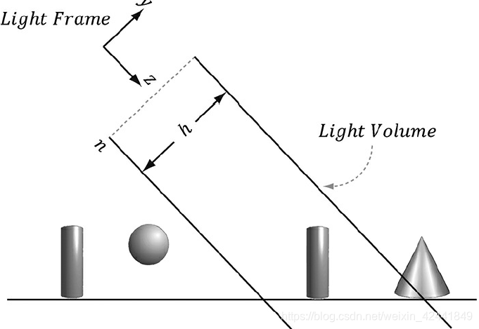
2 正交投影
正交投影主要用以3D科学和工程应用。
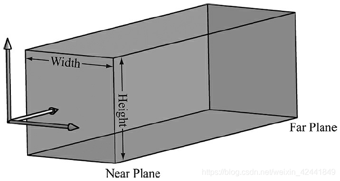
在正交投影中,线都是平行于Z轴。
正交投影矩阵为(推导过程这里省略,可以查看原书):
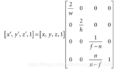
相比于透视投影就是w值不同。
3 投影纹理坐标
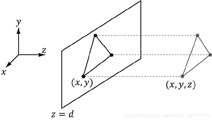
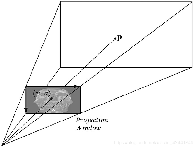
之所以叫投影纹理,是因为它可以让我们投影一个纹理到任意几何体上,比较像一个滑动的投影机,比如下图:
它可以是阴影纹理的一个中间步骤。投影纹理主要是对每一个像素创建一个纹理坐标,从下图中可以看出,纹理坐标(u, v)定义了要被投影到的3D点P。创建纹理坐标的策略是:
1、映射点P到灯光的投影窗口并且转换到NDC坐标系;
2、将投影坐标从NDC坐标系转换到纹理坐标系,然后有效的准换它们到纹理坐标。
第一步可以将灯光认为是一个摄像机,然后定义它的视图矩阵V和投影矩阵P;
第二步可以通过下面的变换从NDC转换到纹理坐标:
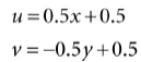
它的变换矩阵:
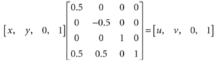
我们称上面的矩阵T(纹理矩阵),也可以直接乘以VPT从世界空间转换到纹理空间。变换过后我们还是要做透视分割来完成变换(查看第五章练习8)。
3.1 实现代码
创建透视纹理坐标代码如下:
struct VertexOut
{
	float4 PosH : SV_POSITION;
	float3 PosW : POSITION;
	float3 TangentW : TANGENT;
	float3 NormalW : NORMAL;
	float2 Tex : TEXCOORD0;
	float4 ProjTex : TEXCOORD1;
};

VertexOut VS(VertexIn vin)
{
	VertexOut vout;
	[…]
	// Transform to light’s projective space.
	vout.ProjTex = mul(float4(vIn.posL, 1.0f), gLightWorldViewProjTexture);
	[…]
	return vout;
}

float4 PS(VertexOut pin) : SV_Target
{
	// Complete projection by doing division by w.
	pin.ProjTex.xyz /= pin.ProjTex.w;

	// Depth in NDC space.
	float depth = pin.ProjTex.z;

	// Sample the texture using the projective texcoords.
	float4 c = gTextureMap.Sample(sampler, pin.ProjTex.xy);
	[…]
}
3.2 截头锥体之外的点
在渲染流水线中,在截头锥体以外的几何体会被裁切。但是,当我们从灯光视角创建投影纹理坐标的时候,还没有执行裁切–我们只简单的投影了顶点。所以在截头锥体以外的投影纹理坐标范围都在[0, 1]以外。对于超出[0, 1]范围的,都是用与地址模式(9.6)。一般情况下都是使用0。
3.3 正交投影
所有可以用以透视投影的也可以使用正交投影,除了下面2点:1、聚光灯照射的点在投影体以外就无法工作,因为聚光灯照射的体积不是一个盒子,但是依然可以对投影体以外的点使用地址模式;
2、对于正交投影,我们不再需要除以w,就是不需要下面这行:
// Complete projection by doing division by w.
pin.ProjTex.xyz /= pin.ProjTex.w;
4 阴影贴图
4.1 算法描述
阴影贴图的思路是,通过渲染到纹理的方式,将场景的深度从灯光视角渲染到深度缓冲,叫做阴影贴图。那些无法被灯光照射的点不会出现的阴影贴图中。
为了完成渲染,我们需要定义灯光的视角矩阵和投影矩阵。透视投影可以模拟聚光灯,正交投影可以模拟平行光。正交投影的盒子体积可能只能照射到场景的一部分,我们可以增加它的参数用以照射整个场景。
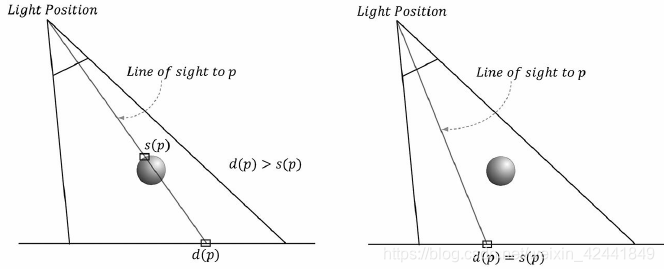
创建好阴影贴图后,我们通过摄像机正常渲染场景。在摄像机视角下,也计算每个点到光源的距离d§,然后从阴影贴图 以灯光照射到该点的纹理坐标 中采样保存的距离s§,这个值是在该直线上,距离灯光最近的点的深度。所以如果d§ > s§,那么该点在阴影中,否则不在阴影中。
深度值的比较是在NDC空间下的,因为阴影贴图是在NDC空间下保存的,如果要想看实现的细节,可以查看工程代码
4.2 偏移(biasing)和走样(aliasing)
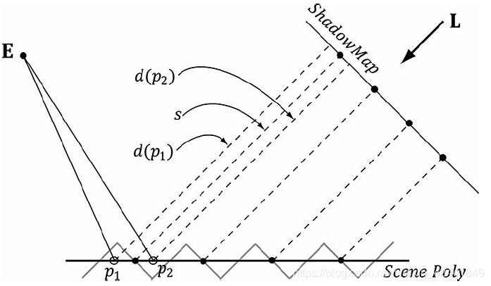
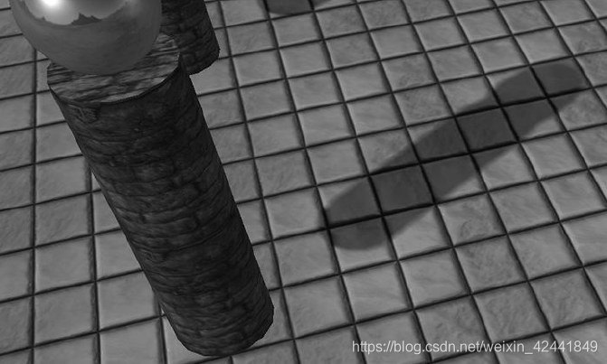
因为阴影贴图的分辨率是有限的,所以它保存的深度值是离散的。这个就导致了走样的问题,我们称之为阴影痤疮(shadow acne)。
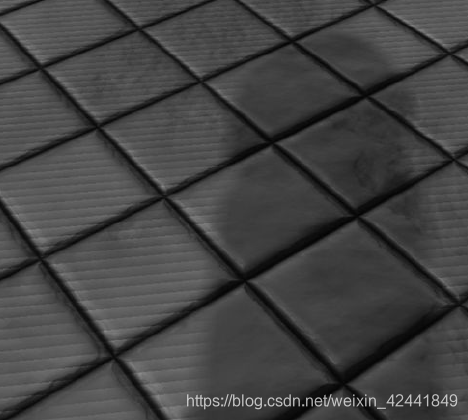
下图展示了阴影痤疮产生的原因。和一个简单的解决方式,对阴影贴图进行一点常量偏移:
如果偏移过多会导致下面的问题,阴影和物体会出现分离:
不幸的是,这个方案不是对所有物体都有效,比如下图中的物体,需要较大的偏差:
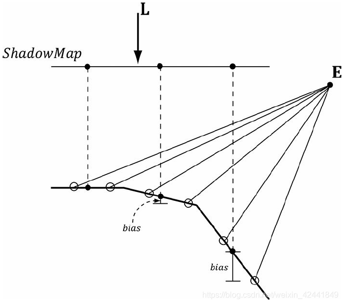
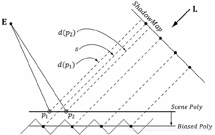
我们需要的是测量出几何体相对于灯光的坡度,然后根据坡度应用偏移。幸运的是图形硬件已经支持了这种偏移,叫坡度缩放偏差(slope-scaled-bias)光栅化状态属性:
typedef struct D3D12_RASTERIZER_DESC {
	[…]
	INT DepthBias;
	FLOAT DepthBiasClamp;
	FLOAT SlopeScaledDepthBias;
	[…]
} D3D12_RASTERIZER_DESC;
1、DepthBias:固定的偏移;
2、DepthBiasClamp:最大支持的偏移;
3、SlopeScaledDepthBias:基于几何体坡度的偏移缩放因子。
我们在渲染阴影纹理的时候应用slope-scaled-bias。这是因为,我们希望偏移基于光源方面几何体的坡度。在我们Demo中,使用下面的值:
// [From MSDN]
// If the depth buffer currently bound to the output-merger stage
// has a UNORM format or no depth buffer is bound the bias value
// is calculated like this:
//
// Bias = (float)DepthBias * r + SlopeScaledDepthBias * MaxDepthSlope;
//
// where r is the minimum representable value > 0 in the
// depth-buffer format converted to float32.
// [/End MSDN]
//
// For a 24-bit depth buffer, r = 1 / 2^24.
//
// Example: DepthBias = 100000 ==> Actual DepthBias = 100000/2^24 = .006
// These values are highly scene dependent, and you will need
// to experiment with these values for your scene to find the
// best values.
D3D12_GRAPHICS_PIPELINE_STATE_DESC smapPsoDesc = opaquePsoDesc;
smapPsoDesc.RasterizerState.DepthBias = 100000;
smapPsoDesc.RasterizerState.DepthBiasClamp = 0.0f;
smapPsoDesc.RasterizerState.SlopeScaledDepthBias = 1.0f;
深度偏移发生在光栅化之后(裁切以后),所以不影响几何体裁切。
对于深度偏移的具体细节,可以SDK中搜索“Depth Bias”,可以查看每个规则是如何应用的。
4.3 PCF滤波器
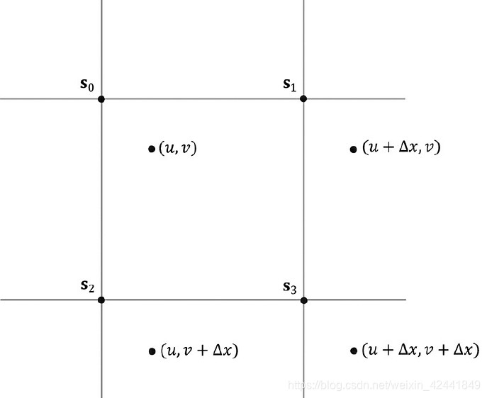
使用透视纹理坐标(u, v)对阴影贴图采样通常情况下并不能采样到某个像素,而是4个像素之间。对于颜色纹理,我们通常使用双重线性差值的方法(9.5.1)。但是[Kilgard01]指出我们不能对深度值求平均,它会导致对像素判定是否在阴影中时出现错误(相同的原因,我们也不能对阴影贴图做mipmap)。相比于对深度值差值,我们使用对结果差值—这个方法叫percentage closer filtering (PCF)。我们使用点滤波器(MIN_MAG_MIP_POINT),然后对坐标(u, v), (u + Δx, v), (u, v + Δx), (u + Δx, v + Δx)进行采样,其中Δx = 1/SHADOW_MAP_SIZE;采样后会有4个像素被命中s0, s1, s2, 和s3包围(u, v),如下图,然后我们对4个点都进行阴影贴图测试,然后对结果进行双线性差值。
实现代码如下:
static const float SMAP_SIZE = 2048.0f;
static const float SMAP_DX = 1.0f / SMAP_SIZE;
…
// Sample shadow map to get nearest depth to light.
float s0 = gShadowMap.Sample(gShadowSam, projTexC.xy).r;
float s1 = gShadowMap.Sample(gShadowSam, projTexC.xy + float2(SMAP_DX, 0)).r;
float s2 = gShadowMap.Sample(gShadowSam, projTexC.xy + float2(0, SMAP_DX)).r;
float s3 = gShadowMap.Sample(gShadowSam, projTexC.xy + float2(SMAP_DX, SMAP_DX)).r;

// Is the pixel depth <= shadow map value?
float result0 = depth <= s0;
float result1 = depth <= s1;
float result2 = depth <= s2;
float result3 = depth <= s3;

// Transform to texel space.
float2 texelPos = SMAP_SIZE*projTexC.xy;

// Determine the interpolation amounts.
float2 t = frac( texelPos );

// Interpolate results.
return lerp( lerp(result0, result1, t.x), lerp(result2, result3, t.x), t.y);
这样一个像素可以一般在阴影中,这样也产生了过渡效果:
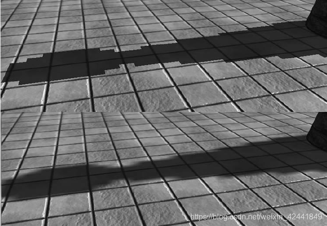
即使增加了滤波器,阴影效果依然很硬,并且由明显的走样。有很多更高级的方案可以使用,可以参考[Uralsky05],比如我们使用更高分辨率的阴影贴图,但是会有更高的开销。
PCF的缺点在于它需要4次采样,在现代显卡上,采样操作是很费性能的操作之一,因为GPU的内存带宽和延时并没有像它计算能力那样得到提高[Möller08]。幸运的是,DX11图形硬件内置了支持PCF的方法SampleCmpLevelZero:
SampleCmpLevelZero method:
Texture2D gShadowMap : register(t1);
SamplerComparisonState gsamShadow : register(s6);

// Complete projection by doing division by w.
shadowPosH.xyz /= shadowPosH.w;

// Depth in NDC space.
float depth = shadowPosH.z;

// Automatically does a 4-tap PCF.
gShadowMap.SampleCmpLevelZero(gsamShadow, shadowPosH.xy, depth).r;
LevelZero代表它只看最高级别的mipmap,对于阴影贴图就比较有用。这个函数并不使用特定的采样对象,而是对比采样器(comparison sampler)。它可以让硬件在采样的过程中对阴影贴图进行对比测试(对结果添加滤波器)。对于PCF,你需要使用D3D12_FILTER_COMPARISON_MIN_MAG_LINEAR_MIP_POINT和设置对比函数为LESS_EQUAL(LESS也可以应用于偏移深度值)。它的第三个参数是要对比的值,对比函数LESS_EQUAL会让我们进行下面的对比:
float result0 = depth <= s0;
float result1 = depth <= s1;
float result2 = depth <= s2;
float result3 = depth <= s3;
然后硬件对结果进行双线性插值结束PCF。
下面代码展示了描述这个采样器:
const CD3DX12_STATIC_SAMPLER_DESC shadow(
	6, // shaderRegister
	D3D12_FILTER_COMPARISON_MIN_MAG_LINEAR_MIP_POINT, // filter
	D3D12_TEXTURE_ADDRESS_MODE_BORDER, // addressU
	D3D12_TEXTURE_ADDRESS_MODE_BORDER, // addressV
	D3D12_TEXTURE_ADDRESS_MODE_BORDER, // addressW
	0.0f, // mipLODBias
	16, // maxAnisotropy
	D3D12_COMPARISON_FUNC_LESS_EQUAL,
	D3D12_STATIC_BORDER_COLOR_OPAQUE_BLACK);
SDK文档中只有下面的格式R32_FLOAT_X8X24_TYPELESS, R32_FLOAT, R24_UNORM_X8_TYPELESS, R16_UNORM,支持比较滤波器。(comparison filters)
目前为止,我们使用4次测试的PCF内核,更大的内核会得到更平滑的边缘,但是会更消耗性能。观察上面的例子,其实只需要在边缘进行PCF,内部是不需要的,根据这个需求,衍生出了其他算法。[Isidoro06b]描述了一种方案,在着色器代码中需要动态分支:只有在边缘进行PCF。这种检测边缘又会带来其他性能开销,所以选择方案的时候要做好利弊分析。
最后,PCF内核可以不做盒子滤波。许多艺术家会随机选取做PCF的点。
4.4 创建阴影贴图
首先要创建阴影贴图,我们创建ShadowMap实例:
mShadowMap = std::make_unique<ShadowMap>(md3dDevice.Get(), 2048, 2048);
然后定义灯光视角矩阵和投影矩阵:
DirectX::BoundingSphere mSceneBounds;

ShadowMapApp::ShadowMapApp(HINSTANCE hInstance) : D3DApp(hInstance)
{
	// Estimate the scene bounding sphere manually since we know how the
	// scene was constructed.
	// The grid is the "widest object" with a width of 20 and depth of
	// 30.0f, and centered at
	// the world space origin. In general, you need to loop over every
	// world space vertex
	// position and compute the bounding sphere.
	mSceneBounds.Center = XMFLOAT3(0.0f, 0.0f, 0.0f);
	mSceneBounds.Radius = sqrtf(10.0f*10.0f + 15.0f*15.0f);
}

void ShadowMapApp::Update(const GameTimer& gt)
{
	[…]
	//
	// Animate the lights (and hence shadows).
	//
	mLightRotationAngle += 0.1f*gt.DeltaTime();
	XMMATRIX R = XMMatrixRotationY(mLightRotationAngle);
	for(int i = 0; i < 3; ++i)
	{
		XMVECTOR lightDir = XMLoadFloat3(&mBaseLightDirections[i]);
		lightDir = XMVector3TransformNormal(lightDir, R);
		XMStoreFloat3(&mRotatedLightDirections[i], lightDir);
	}

	AnimateMaterials(gt);
	UpdateObjectCBs(gt);
	UpdateMaterialBuffer(gt);
	UpdateShadowTransform(gt);
	UpdateMainPassCB(gt);
	UpdateShadowPassCB(gt);
}

void ShadowMapApp::UpdateShadowTransform(const GameTimer& gt)
{
	// Only the first "main" light casts a shadow.
	XMVECTOR lightDir = XMLoadFloat3(&mRotatedLightDirections[0]);
	XMVECTOR lightPos = -2.0f*mSceneBounds.Radius*lightDir;
	XMVECTOR targetPos = XMLoadFloat3(&mSceneBounds.Center);
	XMVECTOR lightUp = XMVectorSet(0.0f, 1.0f, 0.0f, 0.0f);
	XMMATRIX lightView = XMMatrixLookAtLH(lightPos, targetPos, lightUp);
	XMStoreFloat3(&mLightPosW, lightPos);

	// Transform bounding sphere to light space.
	XMFLOAT3 sphereCenterLS;
	XMStoreFloat3(&sphereCenterLS, XMVector3TransformCoord(targetPos, lightView));

	// Ortho frustum in light space encloses scene.
	float l = sphereCenterLS.x - mSceneBounds.Radius;
	float b = sphereCenterLS.y - mSceneBounds.Radius;
	float n = sphereCenterLS.z - mSceneBounds.Radius;
	float r = sphereCenterLS.x + mSceneBounds.Radius;
	float t = sphereCenterLS.y + mSceneBounds.Radius;
	float f = sphereCenterLS.z + mSceneBounds.Radius;
	mLightNearZ = n;
	mLightFarZ = f;
	XMMATRIX lightProj = XMMatrixOrthographicOffCenterLH(l, r, b, t, n, f);

	// Transform NDC space [-1,+1]^2 to texture space [0,1]^2
	XMMATRIX T(
		0.5f, 0.0f, 0.0f, 0.0f,
		0.0f, -0.5f, 0.0f, 0.0f,
		0.0f, 0.0f, 1.0f, 0.0f,
		0.5f, 0.5f, 0.0f, 1.0f);
	XMMATRIX S = lightView*lightProj*T;
	XMStoreFloat4x4(&mLightView, lightView);
	XMStoreFloat4x4(&mLightProj, lightProj);
	XMStoreFloat4x4(&mShadowTransform, S);
}
渲染场景到阴影贴图的代码如下:
void ShadowMapApp::DrawSceneToShadowMap()
{
	mCommandList->RSSetViewports(1, &mShadowMap->Viewport());
	mCommandList->RSSetScissorRects(1, &mShadowMap->ScissorRect());

	// Change to DEPTH_WRITE.
	mCommandList->ResourceBarrier(1, &CD3DX12_RESOURCE_BARRIER::Transition(
		mShadowMap->Resource(),
		D3D12_RESOURCE_STATE_GENERIC_READ,
		D3D12_RESOURCE_STATE_DEPTH_WRITE));

	UINT passCBByteSize = d3dUtil::CalcConstantBufferByteSize(sizeof (PassConstants));

	// Clear the back buffer and depth buffer.
	mCommandList->ClearDepthStencilView(mShadowMap->Dsv(),
		D3D12_CLEAR_FLAG_DEPTH | D3D12_CLEAR_FLAG_STENCIL, 1.0f, 0, 0, nullptr);

	// Set null render target because we are only going to draw to
	// depth buffer. Setting a null render target will disable color writes.
	// Note the active PSO also must specify a render target count of 0.
	mCommandList->OMSetRenderTargets(0, nullptr, false, &mShadowMap->Dsv());

	// Bind the pass constant buffer for the shadow map pass.
	auto passCB = mCurrFrameResource->PassCB->Resource();
	D3D12_GPU_VIRTUAL_ADDRESS passCBAddress = passCB->GetGPUVirtualAddress() + 1*passCBByteSize;
	mCommandList->SetGraphicsRootConstantBufferView(1, passCBAddress);
	mCommandList->SetPipelineState(mPSOs["shadow_opaque"].Get());
	DrawRenderItems(mCommandList.Get(), mRitemLayer[(int)RenderLayer::Opaque]);

	// Change back to GENERIC_READ so we can read the texture in a shader.
	mCommandList->ResourceBarrier(1,
		&CD3DX12_RESOURCE_BARRIER::Transition(
		mShadowMap->Resource(),
		D3D12_RESOURCE_STATE_DEPTH_WRITE,
		D3D12_RESOURCE_STATE_GENERIC_READ));
}
这里我们设置渲染目标为Null,因为我们只渲染阴影贴图。显卡会对只渲染深度的情况优化,它会比渲染颜色明显要快。PSO也要定义渲染目标数量为0:
D3D12_GRAPHICS_PIPELINE_STATE_DESC smapPsoDesc = opaquePsoDesc;
smapPsoDesc.RasterizerState.DepthBias = 100000;
smapPsoDesc.RasterizerState.DepthBiasClamp = 0.0f;
smapPsoDesc.RasterizerState.SlopeScaledDepthBias = 1.0f;
smapPsoDesc.pRootSignature = mRootSignature.Get();
smapPsoDesc.VS =
{
	reinterpret_cast<BYTE*>(mShaders["shadowVS"]->GetBufferPointer()),
		mShaders["shadowVS"]->GetBufferSize()
};
smapPsoDesc.PS =
{
	reinterpret_cast<BYTE*>
		(mShaders["shadowOpaquePS"]->GetBufferPointer()),
		mShaders["shadowOpaquePS"]->GetBufferSize()
};

// Shadow map pass does not have a render target.
smapPsoDesc.RTVFormats[0] = DXGI_FORMAT_UNKNOWN;
smapPsoDesc.NumRenderTargets = 0;

ThrowIfFailed(md3dDevice->CreateGraphicsPipelineState(
	&smapPsoDesc,
	IID_PPV_ARGS(&mPSOs["shadow_opaque"])));
对于这个灯光渲染场景的着色器代码非常简单,因为我们只关心阴影贴图,所以不需要进行其它复杂的像素着色器计算:
//*********************************************************************
// Shadows.hlsl by Frank Luna (C) 2015 All Rights Reserved.
//*********************************************************************

// Include common HLSL code.
#include "Common.hlsl"

struct VertexIn
{
	float3 PosL : POSITION;
	float2 TexC : TEXCOORD;
};

struct VertexOut
{
	float4 PosH : SV_POSITION;
	float2 TexC : TEXCOORD;
};

VertexOut VS(VertexIn vin)
{
	VertexOut vout = (VertexOut)0.0f;
	MaterialData matData = gMaterialData[gMaterialIndex];

	// Transform to world space.
	float4 posW = mul(float4(vin.PosL, 1.0f), gWorld);

	// Transform to homogeneous clip space.
	vout.PosH = mul(posW, gViewProj);

	// Output vertex attributes for interpolation across triangle.
	float4 texC = mul(float4(vin.TexC, 0.0f, 1.0f), gTexTransform);
	vout.TexC = mul(texC, matData.MatTransform).xy;

	return vout;
}

// This is only used for alpha cut out geometry, so that shadows
// show up correctly. Geometry that does not need to sample a
// texture can use a NULL pixel shader for depth pass.
void PS(VertexOut pin)
{
	// Fetch the material data.
	MaterialData matData = gMaterialData[gMaterialIndex];
	float4 diffuseAlbedo = matData.DiffuseAlbedo;
	uint diffuseMapIndex = matData.DiffuseMapIndex;

	// Dynamically look up the texture in the array.
	diffuseAlbedo *= gTextureMaps[diffuseMapIndex].Sample(gsamAnisotropicWrap, pin.TexC);

	#ifdef ALPHA_TEST
		// Discard pixel if texture alpha < 0.1. We do this test as soon
		// as possible in the shader so that we can potentially exit the
		// shader early, thereby skipping the rest of the shader code.
		clip(diffuseAlbedo.a - 0.1f);
	#endif
}
这里像素着色器没有返回值,是因为我们只输出深度值。像素着色器只用以裁剪透明的像素片段。如果不需要根据透明度进行裁剪,我们可以设置像素着色器为null,这样可以让性能更高。
如果渲染阴影贴图的时候包含曲面细分几何体,我们需要曲面细分要和摄像机渲染时的细分保持一致;也就是说相机与物体的距离和光源与物体的距离要差不多,否则阴影会出现错误。一种优化的方案是,渲染阴影贴图的时候不使用曲面细分。(这种优化用准确性交换速度)
4.5 阴影因子
阴影因子代表像素是否在阴影中(0~1),CalcShadowFactor在Common.hlsl实现:
float CalcShadowFactor(float4 shadowPosH)
{
	// Complete projection by doing division by w.
	shadowPosH.xyz /= shadowPosH.w;

	// Depth in NDC space.
	float depth = shadowPosH.z;
	uint width, height, numMips;
	gShadowMap.GetDimensions(0, width, height, numMips);

	// Texel size.
	float dx = 1.0f / (float)width;
	float percentLit = 0.0f;
	const float2 offsets[9] =
	{
		float2(-dx, -dx), float2(0.0f, -dx), float2(dx, -dx),
		float2(-dx, 0.0f), float2(0.0f, 0.0f), float2(dx, 0.0f),
		float2(-dx, +dx), float2(0.0f, +dx), float2(dx, +dx)
	};

	[unroll]
	for(int i = 0; i < 9; ++i)
	{
		percentLit += gShadowMap.SampleCmpLevelZero(gsamShadow,
			shadowPosH.xy + offsets[i], depth).r;
	}

	return percentLit / 9.0f;
}
在我们的模型中,阴影因子会和我们直接光照计算的结果有冲突:
// Only the first light casts a shadow.
float3 shadowFactor = float3(1.0f, 1.0f, 1.0f);
shadowFactor[0] = CalcShadowFactor(pin.ShadowPosH);
const float shininess = (1.0f - roughness) * normalMapSample.a;

Material mat = { diffuseAlbedo, fresnelR0, shininess };
float4 directLight = ComputeLighting(gLights,
	mat, pin.PosW,
	bumpedNormalW, toEyeW, shadowFactor);

float4 ComputeLighting(Light gLights[MaxLights],
	Material mat,
	float3 pos, float3 normal, float3
	toEye,
	float3 shadowFactor)
{
	float3 result = 0.0f;
	int i = 0;
	#if (NUM_DIR_LIGHTS > 0)
		for(i = 0; i < NUM_DIR_LIGHTS; ++i)
		{
			result += shadowFactor[i] *
			ComputeDirectionalLight(gLights[i], mat, normal, toEye);
		}
	#endif
	#if (NUM_POINT_LIGHTS > 0)
		for(i = NUM_DIR_LIGHTS; i < NUM_DIR_LIGHTS+NUM_POINT_LIGHTS; ++i)
		{
			result += ComputePointLight(gLights[i], mat, pos, normal, toEye);
		}
	#endif
	#if (NUM_SPOT_LIGHTS > 0)
		for(i = NUM_DIR_LIGHTS + NUM_POINT_LIGHTS; i < NUM_DIR_LIGHTS +
			NUM_POINT_LIGHTS + NUM_SPOT_LIGHTS; ++i)
		{
			result += ComputeSpotLight(gLights[i], mat, pos, normal, toEye);
		}
	#endif

	return float4(result, 0.0f);
}
阴影因子不影响环境光,也不影响来自环境贴图的反射光。
4.6 阴影贴图测试
进行比较d§ 和 s§,它们都是在NDC空间才能进行比较,gShadowTransform矩阵可以从世界坐标系变换到阴影贴图坐标系:
// Generate projective tex-coords to project shadow map onto scene
// in vertex shader.
vout.ShadowPosH = mul(posW, gShadowTransform);

// Do the shadow map test in pixel shader.
float3 shadowFactor = float3(1.0f, 1.0f, 1.0f);
shadowFactor[0] = CalcShadowFactor(pin.ShadowPosH);
gShadowTransform矩阵保存在per-pass constant。
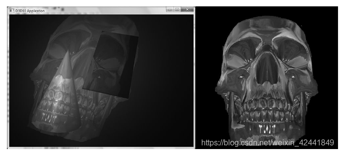
4.7 渲染阴影贴图
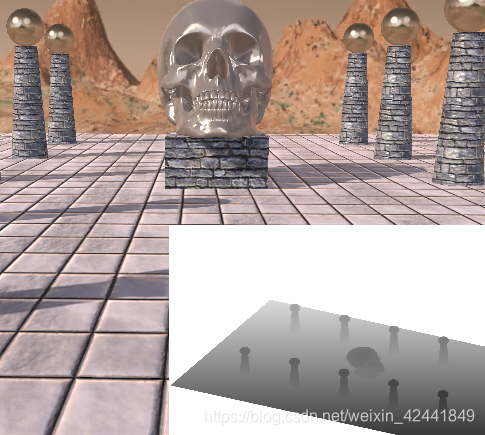
本Demo中,我们在右下角也渲染了阴影贴图,这样方便做测试:
5 大PCF内核
略 可查看原书
6 总结
- 渲染目标不是必须要设置为后置缓冲,也可以渲染到纹理;很多效果,比如阴影贴图,水流模拟等都需要用到渲染到纹理技术;
- 正交投影的可视区域是一个盒子,它主要用以3D科学和工程应用。在这里可以用来生成平行光产生的阴影;
- 投影纹理之所以这么叫,是因为它让我们可以将纹理投影到任意几何体上。投影纹理最主要的就是为每个像素创建纹理坐标,这个纹理坐标叫做:projective texture coordinates;
- 阴影贴图是一个实时阴影技术,支持任意几何体的阴影。它的思路是创建灯光视角下的深度信息到阴影贴图;然后从摄像机视角渲染场景,对像素到灯光的距离和阴影贴图记录的深度值进行比较,来判定当前像素是否在阴影中;
- 反走样是阴影贴图中最大的挑战。因为阴影贴图的分辨率是有限的,所以阴影贴图的每个像素对应的场景中的一片区域,所以对它的采样是不连续的,这就导致了叫shadow acne的走样效果。使用图形硬件支持的slope-scaled-bias,是通用的修复上述问题的策略。有限分辨率的应用贴图导致阴影边缘走样的问题,PCF是最流行的修复它的技术。更多更高级的反走样技术是cascaded shadow maps and variance shadow maps。