学习目标
- 理解为什么需要法线贴图;
- 学习法线贴图如何保存;
- 学习法线贴图如何创建;
- 学习法线贴图中的法向量的坐标系统是如何与物体空间的三角形的坐标系统关联的;
- 学习如何在顶点和像素着色器中实现法线贴图。
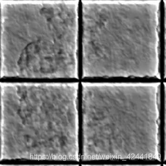
1 使用法线贴图的原因
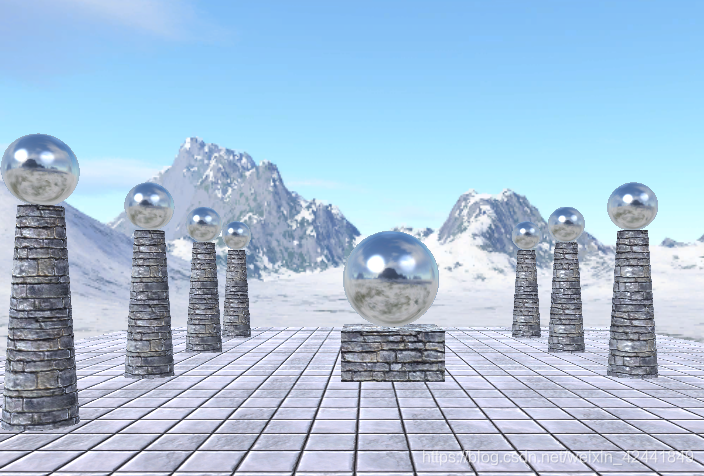
找到一种方法在光滑的平面上,显示出更多的细节(比如粗糙的砖块)。
如果使用曲面细分是可以增加实际的细节的,但是我们还是需要一种方法来指定新增加的顶点的法向量。如果直接根据光照来烘焙纹理,这种方法如果灯光移动后,效果就会出问题。
所以要使用法线贴图:
2 法线贴图
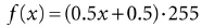
一个法线贴图是一张纹理,其每个通道保存x,y,z坐标值,所以每个像素保存了一个法线向量:
一个单位向量其每个组件值的值域为[−1, 1],我们可以经过下面的运算,将其转换到0-255:
如果要再将其准换回[−1, 1],就对每个通道执行:
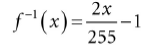
我们不需要自己去做压缩操作,PhotoShop的插件可以帮忙把图像转化成法线贴图。但是在着色器中,我们需要自己做解压缩操作:
float3 normalT = gNormalMap.Sample(gTriLinearSam, pin.Tex);
normalT每个组件的值域为0 ≤ r, g, b ≤ 1;所以该函数已经为我们做了一半的解压缩操作,我们只需要再将其转换到[−1, 1]即可:
// Uncompress each component from [0,1] to [-1,1].
normalT = 2.0f*normalT - 1.0f;
Photoshop的插件可以在 https://developer.nvidia.com/nvidia-texture-tools-adobe-photoshop 下载到;还有其它一些创建法线贴图的工具:http://www.crazybump.com/ 和 http://shadermap.com/home/ ;还有一些工具可以从高分辨率模型上创建法线贴图:https://www.nvidia.com/object/melody_home.html 。
如果你要使用压缩纹理格式保存法线贴图,使用BC7 (DXGI_FORMAT_BC7_UNORM)格式是最好的效果,它可以减少由压缩法线贴图造成的错误。对于BC6和BC7格式,DirectX SDK有一个例子叫“BC6HBC7EncoderDecoder11”,它可以将你的法线贴图转换到BC6或者BC7。
3 纹理/切线空间
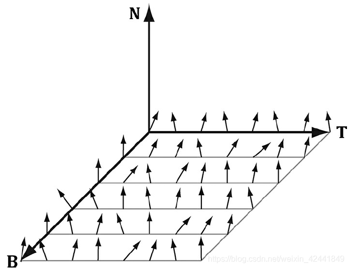
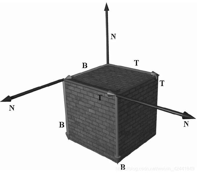
纹理通过平移和旋转后贴到三角形上后,合并三角形的法向量N,我们在三角形所在的平面上生成一个3D TBN-basis的坐标系,叫做纹理空间或者切线空间。注意该空间对于不同三角形是不一样的。
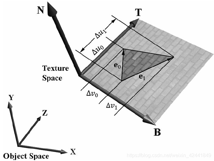
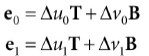
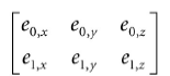
法线贴图的法向量是在纹理空间定义的,但是灯光是在世界坐标系下的,所以我们需要将它们转换到同一个坐标系下才能正确计算光照。所以首先我们要纹理空间关联到它的物体局部坐标系中。令v0, v1, 和 v2定义一个3D三角形的三个顶点,对应的纹理坐标为(u0, v0), (u1, v1), 和(u2, v2)。令e0 = v1 − v0和e1 = v2 − v0是三角形的两条边,并且对于的纹理三角形的两条边:(Δu0, Δv0) = (u1 − u0, v1 − v0) 和 (Δu1, Δv1) = (u2 − u0, v2 − v0) :
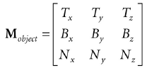
表达了向量坐标关联到物体空间,我们得到矩阵方程:
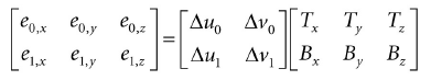
我们知道三角形顶点的物体空间坐标,也知道边的物体空间坐标:
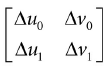
我们也知道纹理坐标:
解T和B的物体空间坐标:
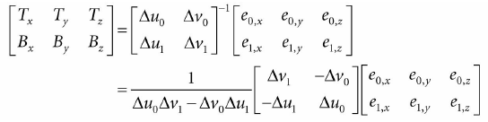
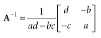
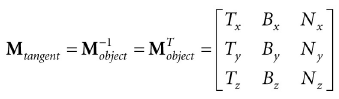
综上所述,我们使用逆矩阵

向量T和B在物体坐标系中不是单位长度,如果有扭曲,它们也不是正交的。
T,V和N向量代表了切线,次法线和法线向量。
4 顶点的切线空间
上一节,我们衍生出了逐三角形的切线空间,如果我们使用它来进行法线贴图映射,物体表面会产生三角形化的效果。所以我们定义逐顶点的切向量,然后进行均值计算来模拟光滑平面:
1、任意顶点V的切向量T通过所有共享它的三角形切向量的平均值来获取;
2、任意顶点的次切向量B通过所有共享它的三角形次切向量的平均值来获取。
通常情况下,进行均值运算后,TBN-bases需要标准正交化,所以向量要进行正交运算和转换为单位长度。这个通常使用Gram-Schmidt步骤。代码可以在下面网站中找到,对任意三角网格创建逐向量的切线空间:http://www.terathon.com/code/tangent.html 。
在我们的系统中,我们不需要直接保存次切向量B到内存,可以通过计算获得B = N × T,所以顶点结构为:
struct Vertex
{
	XMFLOAT3 Pos;
	XMFLOAT3 Normal;
	XMFLOAT2 Tex;
	XMFLOAT3 TangentU;
};
回顾我们在GeometryGenerator中创建网格的步骤,计算纹理空间的切线T。向量Y在盒子或者格子网格中非常容易计算。对于圆柱体和球体,每个顶点的切向量可以通过两个点P(u, v)然后计算∂p/∂u来获得(其中u使用的是u的纹理坐标)。
5 切线空间和物体空间之间的转换
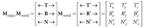
现在网格的每个顶点我们有一个标准正交的TBN-basis,并且关联到物体空间。我们可以通过下面的变换矩阵进行转化:
因为它是标准正交的,所以它的逆矩阵就是它的转置矩阵,所以从物体空间到切线空间为:
在着色器代码中,我们需要将它们转换到世界坐标系中:
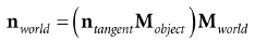
因为矩阵的乘法具有结合律,所以:
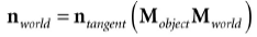
并且:
所以要从切线空间转换到世界坐标系,我们只需要在世界坐标系下描述切线方向轴,即可得到变换矩阵。
因为我们只需要转换向量,所以我们只需要一个3x3矩阵。
6 法线贴图的着色器代码
我们总结一下实现的步骤:
1、通过各种工具或者软件创建法线贴图并保存到图像文件,在程序初始化的时候读取文件创建纹理;
2、对每个三角形,计算它的切向量T;
3、在顶点着色器中,转换法向量和切向量到世界坐标系中,并且输出到像素着色器;
4、使用差值后的切向量和法向量,我们在三角形表面的每个像素点创建TBN-basis,然后用它们将采样到的法向量变换到世界坐标系。然后就可以使用它来进行光照计算。
为了帮助我们实现法线贴图,我们在Common.hlsl添加了下面的函数:
//--------------------------------------------------------------------
// Transforms a normal map sample to world space.
//--------------------------------------------------------------------
float3 NormalSampleToWorldSpace(float3 normalMapSample,
float3 unitNormalW,
float3 tangentW)
{
// Uncompress each component from [0,1] to [-1,1].
float3 normalT = 2.0f*normalMapSample - 1.0f;
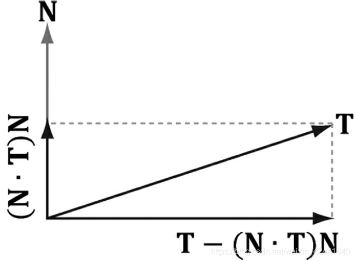
// Build orthonormal basis.
float3 N = unitNormalW;
float3 T = normalize(tangentW - dot(tangentW, N)*N);
float3 B = cross(N, T);
float3x3 TBN = float3x3(T, B, N);
// Transform from tangent space to world space.
float3 bumpedNormalW = mul(normalT, TBN);
return bumpedNormalW;
}
这个函数在像素着色器中可以这样使用:
float3 normalMapSample = gNormalMap.Sample(samLinear, pin.Tex).rgb;
float3 bumpedNormalW = NormalSampleToWorldSpace(
	normalMapSample,
	pin.NormalW,
	pin.TangentW);
可能有两行不太好理解的是:
float3 N = unitNormalW;
float3 T = normalize(tangentW - dot(tangentW, N)*N);
结果差值运算后,切向量和法向量可能不是标准正交的,这个代码确保T和N是标准正交的
完整的着色器代码如下:
//*********************************************************************
// Default.hlsl by Frank Luna (C) 2015 All Rights Reserved.
//*********************************************************************
// Defaults for number of lights.
#ifndef NUM_DIR_LIGHTS
	#define NUM_DIR_LIGHTS 3
#endif
#ifndef NUM_POINT_LIGHTS
	#define NUM_POINT_LIGHTS 0
#endif
#ifndef NUM_SPOT_LIGHTS
	#define NUM_SPOT_LIGHTS 0
#endif

// Include common HLSL code.
#include “Common.hlsl”

struct VertexIn
{
	float3 PosL : POSITION;
	float3 NormalL : NORMAL;
	float2 TexC : TEXCOORD;
	float3 TangentU : TANGENT;
};

struct VertexOut
{
	float4 PosH : SV_POSITION;
	float3 PosW : POSITION;
	float3 NormalW : NORMAL;
	float3 TangentW : TANGENT;
	float2 TexC : TEXCOORD;
};

VertexOut VS(VertexIn vin)
{
	VertexOut vout = (VertexOut)0.0f;

	// Fetch the material data.
	MaterialData matData = gMaterialData[gMaterialIndex];

	// Transform to world space.
	float4 posW = mul(float4(vin.PosL, 1.0f), gWorld);
	vout.PosW = posW.xyz;

	// Assumes nonuniform scaling; otherwise, need to use
	// inverse-transpose of world matrix.
	vout.NormalW = mul(vin.NormalL, (float3x3)gWorld);
	vout.TangentW = mul(vin.TangentU, (float3x3)gWorld);

	// Transform to homogeneous clip space.
	vout.PosH = mul(posW, gViewProj);

	// Output vertex attributes for interpolation across triangle.
	float4 texC = mul(float4(vin.TexC, 0.0f, 1.0f), gTexTransform);
	vout.TexC = mul(texC, matData.MatTransform).xy;

	return vout;
}

float4 PS(VertexOut pin) : SV_Target
{
	// Fetch the material data.
	MaterialData matData = gMaterialData[gMaterialIndex];
	float4 diffuseAlbedo = matData.DiffuseAlbedo;
	float3 fresnelR0 = matData.FresnelR0;
	float roughness = matData.Roughness;
	uint diffuseMapIndex = matData.DiffuseMapIndex;
	uint normalMapIndex = matData.NormalMapIndex;

	// Interpolating normal can unnormalize it, so renormalize it.
	pin.NormalW = normalize(pin.NormalW);
	float4 normalMapSample = gTextureMaps[normalMapIndex].Sample(gsamAnisotropicWrap, pin.TexC);
	float3 bumpedNormalW = NormalSampleToWorldSpace(
		normalMapSample.rgb, pin.NormalW,
		pin.TangentW);

	// Uncomment to turn off normal mapping.
	//bumpedNormalW = pin.NormalW;
	// Dynamically look up the texture in the array.
	diffuseAlbedo *= gTextureMaps[diffuseMapIndex].Sample(gsamAnisotropicWrap, pin.TexC);

	// Vector from point being lit to eye.
	float3 toEyeW = normalize(gEyePosW - pin.PosW);

	// Light terms.
	float4 ambient = gAmbientLight*diffuseAlbedo;

	// Alpha channel stores shininess at per-pixel level.
	const float shininess = (1.0f - roughness) * normalMapSample.a;
	Material mat = { diffuseAlbedo, fresnelR0, shininess };
	float3 shadowFactor = 1.0f;
	float4 directLight = ComputeLighting(gLights, mat, pin.PosW,
	bumpedNormalW, toEyeW, shadowFactor);
	float4 litColor = ambient + directLight;

	// Add in specular reflections.
	float3 r = reflect(-toEyeW, bumpedNormalW);
	float4 reflectionColor = gCubeMap.Sample(gsamLinearWrap, r);
	float3 fresnelFactor = SchlickFresnel(fresnelR0, bumpedNormalW, r);
	litColor.rgb += shininess * fresnelFactor * reflectionColor.rgb;

	// Common convention to take alpha from diffuse albedo.
	litColor.a = diffuseAlbedo.a;

	return litColor;
}
其中bumpedNormalW不仅用以光照计算,还用以反射计算。另外alpha通道还可以用来保存发光度,用来控制逐像素的发光程度。
7 总结
- 法线贴图的策略就是,保存物体的法线到一张纹理中,然后使用逐像素的法线来进行计算;
- 法线贴图就是各个通道来分别保存法向量的x y z,它可以通过多种工具制作生成;
- 法线贴图中的法向量是在纹理坐标系下的,如果要进行光照计算,需要将它转换到世界坐标系下,TBN-bases可以帮助每个顶点的法向量从纹理坐标转换到世界坐标系。