代码工程地址:
https://github.com/jiabaodan/Direct12BookReadingNotes
学习目标
- 熟悉Direct3D接口的定义,保存和绘制几何数据 ;
- 学习编写基本的顶点和像素着色器;
- 学习使用渲染流水线状态对象来配置渲染流水线;
- 理解如何创建常数缓存数据(constant buffer data),并且熟悉根签名?(root signature);
1 顶点和输入布局
下面的代码定义了2类顶点:
struct Vertex1
{
	XMFLOAT3 Pos;
	XMFLOAT4 Color;
};

struct Vertex2
{
	XMFLOAT3 Pos;
	XMFLOAT3 Normal;
	XMFLOAT2 Tex0;
	XMFLOAT2 Tex1;
};
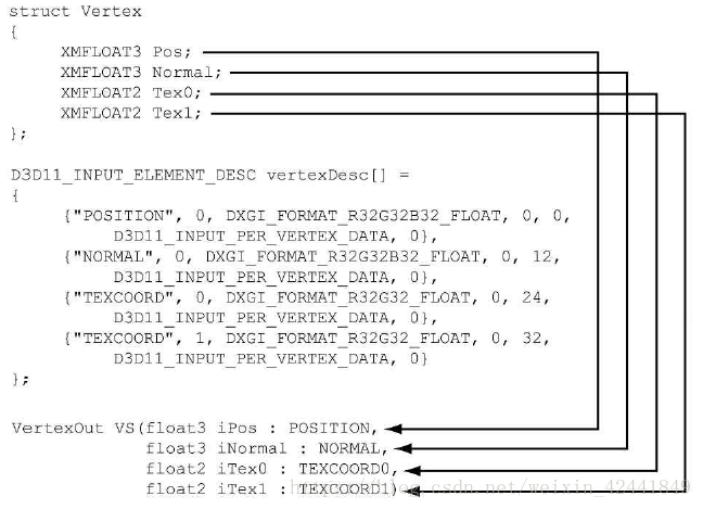
当我们定义完一个顶点结构以后,我们需要提供一个描述来让Direct3D知道每个组件是什么作用,这个描述由Direct3D结构体D3D12_INPUT_LAYOUT_DESC通过输入布局描述(input layout description)的形式提供:
typedef struct D3D12_INPUT_LAYOUT_DESC
{
	const D3D12_INPUT_ELEMENT_DESC *pInputElementDescs;
	UINT NumElements;
} D3D12_INPUT_LAYOUT_DESC;
一个输入布局描述就是D3D12_INPUT_ELEMENT_DESC的数组,和数组的个数。
数组中每个元素用来描述顶点结构中对应的组件,D3D12_INPUT_ELEMENT_DESC结构体定义如下:
typedef struct D3D12_INPUT_ELEMENT_DESC
{
	LPCSTR SemanticName;
	UINT SemanticIndex;
	DXGI_FORMAT Format;
	UINT InputSlot;
	UINT AlignedByteOffset;
	D3D12_INPUT_CLASSIFICATION InputSlotClass;
	UINT InstanceDataStepRate;
} D3D12_INPUT_ELEMENT_DESC;
- SemanticName:关联到顶点结构中每个元素,它主要用以将顶点结构中的元素映射到顶点着色器输入签名中使用;
- SemanticIndex:关联到语义上的索引,使相同的语义可以多次使用,以索引区分,如上图;
- Format:由DXGI_FORMAT枚举类型定义的类型,下面是一些常用的值:
		DXGI_FORMAT_R32_FLOAT // 1D 32-bit float scalar
		DXGI_FORMAT_R32G32_FLOAT // 2D 32-bit float vector
		DXGI_FORMAT_R32G32B32_FLOAT // 3D 32-bit float vector
		DXGI_FORMAT_R32G32B32A32_FLOAT // 4D 32-bit float vector
		DXGI_FORMAT_R8_UINT // 1D 8-bit unsigned integer scalar
		DXGI_FORMAT_R16G16_SINT // 2D 16-bit signed integer vector
		DXGI_FORMAT_R32G32B32_UINT // 3D 32-bit unsigned integer vector
		DXGI_FORMAT_R8G8B8A8_SINT // 4D 8-bit signed integer vector
		DXGI_FORMAT_R8G8B8A8_UINT // 4D 8-bit unsigned integer vector
- InputSlot:定义元素传进来的输入槽,Direct3D支持16个输入槽(0~15);
- AlignedByteOffset:每个元素的偏移量,单位是字节:
		struct Vertex2
		{
			XMFLOAT3 Pos; // 0-byte offset
			XMFLOAT3 Normal; // 12-byte offset
			XMFLOAT2 Tex0; // 24-byte offset
			XMFLOAT2 Tex1; // 32-byte offset
		};
- InputSlotClass:目前暂时都设置为D3D12_INPUT_PER_VERTEX_DATA,其他值用以实例化技术;
- InstanceDataStepRate:目前暂时都设置为0,其他值用以实例化技术;
对于之前描述的两个顶点结构,其对应的输入布局描述如下:
D3D12_INPUT_ELEMENT_DESC desc1[] =
{
	{"POSITION", 0, DXGI_FORMAT_R32G32B32_FLOAT, 0, 0, D3D12_INPUT_PER_VERTEX_DATA, 0},
	{"COLOR", 0, DXGI_FORMAT_R32G32B32A32_FLOAT, 0, 12, D3D12_INPUT_PER_VERTEX_DATA, 0}
};

D3D12_INPUT_ELEMENT_DESC desc2[] =
{
	{"POSITION", 0, DXGI_FORMAT_R32G32B32_FLOAT, 0, 0, D3D12_INPUT_PER_VERTEX_DATA, 0},
	{"NORMAL", 0, DXGI_FORMAT_R32G32B32_FLOAT, 0, 12, D3D12_INPUT_PER_VERTEX_DATA, 0},
	{"TEXCOORD", 0, DXGI_FORMAT_R32G32_FLOAT, 0, 24, D3D12_INPUT_PER_VERTEX_DATA, 0}
	{"TEXCOORD", 1, DXGI_FORMAT_R32G32_FLOAT, 0, 32, D3D12_INPUT_PER_VERTEX_DATA, 0}
};
2 顶点缓冲(VERTEX BUFFERS)
为了让GPU访问到顶点数组,我们需要将它们保存在一个叫缓冲(buffer)的GPU资源中(ID3D12Resource),用来保存顶点数据的缓冲叫做顶点缓冲。
如之前4.3.8,我们通过填写一个D3D12_RESOURCE_DESC结构体,创建一个ID3D12Resource对象来描述缓冲资源,然后调用ID3D12Device::CreateCommittedResource方法。Direct3D 12提供了一个C++封装的类CD3DX12_RESOURCE_DESC(继承自D3D12_RESOURCE_DESC),它提供了一个更加方便的构造方法:
static inline CD3DX12_RESOURCE_DESC Buffer(
	UINT64 width,
	D3D12_RESOURCE_FLAGS flags = D3D12_RESOURCE_FLAG_NONE,
	UINT64 alignment = 0 )
{
	return CD3DX12_RESOURCE_DESC(
		D3D12_RESOURCE_DIMENSION_BUFFER,
		alignment, width, 1, 1, 1,
		DXGI_FORMAT_UNKNOWN, 1, 0,
		D3D12_TEXTURE_LAYOUT_ROW_MAJOR, flags );
}
with代表了缓冲中的字节数。
对于静态的几何体,我们将顶点缓冲放到默认堆中(default heap)((D3D12_HEAP_TYPE_DEFAULT)用以优化性能;为了创建实际的顶点缓冲资源,我们需要创建一个类型为D3D12_HEAP_TYPE_UPLOAD的上传缓冲(upload buffer)资源。
因为中间的上传缓冲需要在默认缓冲(default buffer)中初始化,所以我们在d3dUtil.h/.cpp中编写下面函数,用以避免重复代码:
Microsoft::WRL::ComPtr<ID3D12Resource> d3dUtil::CreateDefaultBuffer(
	ID3D12Device* device,
	ID3D12GraphicsCommandList* cmdList,
	const void* initData,
	UINT64 byteSize,
	Microsoft::WRL::ComPtr<ID3D12Resource>& uploadBuffer)
{
	ComPtr<ID3D12Resource> defaultBuffer;

	// Create the actual default buffer resource.
	ThrowIfFailed(device->CreateCommittedResource(
		&CD3DX12_HEAP_PROPERTIES(D3D12_HEAP_TYPE_DEFAULT),
		D3D12_HEAP_FLAG_NONE,
		&CD3DX12_RESOURCE_DESC::Buffer(byteSize),
		D3D12_RESOURCE_STATE_COMMON,
		nullptr,
		IID_PPV_ARGS(defaultBuffer.GetAddressOf())));

	// In order to copy CPU memory data into our default buffer, we need
	// to create an intermediate upload heap.
	ThrowIfFailed(device->CreateCommittedResource(
		&CD3DX12_HEAP_PROPERTIES(D3D12_HEAP_TYPE_UPLOAD),
		D3D12_HEAP_FLAG_NONE,
		&CD3DX12_RESOURCE_DESC::Buffer(byteSize),
		D3D12_RESOURCE_STATE_GENERIC_READ,
		nullptr,
		IID_PPV_ARGS(uploadBuffer.GetAddressOf())));

	// Describe the data we want to copy into the default buffer.
	D3D12_SUBRESOURCE_DATA subResourceData = {};
	subResourceData.pData = initData;
	subResourceData.RowPitch = byteSize;
	subResourceData.SlicePitch = subResourceData.RowPitch;

	// Schedule to copy the data to the default buffer resource.
	// At a high level, the helper function UpdateSubresources
	// will copy the CPU memory into the intermediate upload heap.
	// Then, using ID3D12CommandList::CopySubresourceRegion,
	// the intermediate upload heap data will be copied to mBuffer.
	cmdList->ResourceBarrier(1,
		&CD3DX12_RESOURCE_BARRIER::Transition(defaultBuffer.D3D12_RESOURCE_STATE_COMMON,
		D3D12_RESOURCE_STATE_COPY_DEST));

	UpdateSubresources<1>(cmdList,
		defaultBuffer.Get(), uploadBuffer.Get(),
		0, 0, 1, &subResourceData);

	cmdList->ResourceBarrier(1,
		&CD3DX12_RESOURCE_BARRIER::Transition(defaultBuffer.D3D12_RESOURCE_STATE_COPY_DEST,
		D3D12_RESOURCE_STATE_GENERIC_READ));

	// Note: uploadBuffer has to be kept alive after the above function
	// calls because the command list has not been executed yet that
	// performs the actual copy.
	// The caller can Release the uploadBuffer after it knows the copy
	// has been executed.

	return defaultBuffer;
}
D3D12_SUBRESOURCE_DATA结构体定义如下:
typedef struct D3D12_SUBRESOURCE_DATA
{
	const void *pData;
	LONG_PTR RowPitch;
	LONG_PTR SlicePitch;
} D3D12_SUBRESOURCE_DATA;
- pData:指向包含缓冲中需要初始化数据的内存的指针,如果该缓冲可以保存n个顶点,那么内存数组至少也要有n个顶点的内存;
- RowPitch:对于缓冲来说,是我们要复制的数据的大小;
- SlicePitch:对于缓冲来说,是我们要复制的数据的大小;
下面的代码展示了该类使用的一个例子:
Vertex vertices[] =
{
	{ XMFLOAT3(-1.0f, -1.0f, -1.0f), XMFLOAT4(Colors::White) },
	{ XMFLOAT3(-1.0f, +1.0f, -1.0f), XMFLOAT4(Colors::Black) },
	{ XMFLOAT3(+1.0f, +1.0f, -1.0f), XMFLOAT4(Colors::Red) },
	{ XMFLOAT3(+1.0f, -1.0f, -1.0f), XMFLOAT4(Colors::Green) },
	{ XMFLOAT3(-1.0f, -1.0f, +1.0f), XMFLOAT4(Colors::Blue) },
	{ XMFLOAT3(-1.0f, +1.0f, +1.0f), XMFLOAT4(Colors::Yellow) },
	{ XMFLOAT3(+1.0f, +1.0f, +1.0f), XMFLOAT4(Colors::Cyan) },
	{ XMFLOAT3(+1.0f, -1.0f, +1.0f), XMFLOAT4(Colors::Magenta) }
};

const UINT64 vbByteSize = 8 * sizeof(Vertex);
ComPtr<ID3D12Resource> VertexBufferGPU = nullptr;
ComPtr<ID3D12Resource> VertexBufferUploader = nullptr;

VertexBufferGPU = d3dUtil::CreateDefaultBuffer(md3dDevice.Get(),
	mCommandList.Get(),
	vertices,
	vbByteSize,
	VertexBufferUploader);
顶点的定义如下:

struct Vertex
{
	XMFLOAT3 Pos;
	XMFLOAT4 Color;
};
为了绑定顶点缓冲到渲染管线,我们需要创建一个顶点缓冲描述(vertex buffer view)。和RTV(render target view)不同,我们不需要为顶点缓冲描述创建描述堆(descriptor heap),它可以通过D3D12_VERTEX_BUFFER_VIEW_DESC结构来表示:
typedef struct D3D12_VERTEX_BUFFER_VIEW
{
	D3D12_GPU_VIRTUAL_ADDRESS BufferLocation;
	UINT SizeInBytes;
	UINT StrideInBytes;
} D3D12_VERTEX_BUFFER_VIEW;
- BufferLocation:需要创建的描述的虚拟地址,可以使用ID3D12Resource::GetGPUVirtualAddress方法来获取;
- SizeInBytes:从BufferLocation开始,描述需要的字符数;
- StrideInBytes:每个顶点元素的大小,单位是字节;
当我们创建好一个顶点缓冲,并为它创建好描述后,我们可以把它绑定到渲染管线的一个输入槽,用以将顶点数据输入到输入阶段;这个过程可以使用下面函数完成:
void ID3D12GraphicsCommandList::IASetVertexBuffers(
	UINT StartSlot,
	UINT NumBuffers,
	const D3D12_VERTEX_BUFFER_VIEW *pViews);
- StartSlot:输入槽的序号(0~15);
- NumBuffers:需要绑定的顶点缓冲的数量,如果开始序号是k,要绑定n个,那么绑定的序号为k,k+1…;
- pViews:指向第一个顶点缓冲描述的指针;
下面是一个调用的例子:
D3D12_VERTEX_BUFFER_VIEW vbv;

vbv.BufferLocation = VertexBufferGPU->GetGPUVirtualAddress();
vbv.StrideInBytes = sizeof(Vertex);
vbv.SizeInBytes = 8 * sizeof(Vertex);

D3D12_VERTEX_BUFFER_VIEW vertexBuffers[1] = { vbv };
mCommandList->IASetVertexBuffers(0, 1, vertexBuffers);
一个顶点缓冲将会保持在输入的槽,知道它被改变,所以你的代码应该类似下面:
ID3D12Resource* mVB1; // stores vertices of type Vertex1
ID3D12Resource* mVB2; // stores vertices of type Vertex2

D3D12_VERTEX_BUFFER_VIEW_DESC mVBView1; // view to mVB1
D3D12_VERTEX_BUFFER_VIEW_DESC mVBView2; // view to mVB2
/*…Create the vertex buffers and views…*/

mCommandList->IASetVertexBuffers(0, 1, &VBView1);
/* …draw objects using vertex buffer 1… */
mCommandList->IASetVertexBuffers(0, 1, &mVBView2);
/* …draw objects using vertex buffer 2… */
设置顶点缓冲到输入槽并没有开始绘制,它只是让顶点做好输入到渲染管线的准备,最终实际的渲染步骤是由ID3D12GraphicsCommandList::DrawInstanced方法完成:
void ID3D12CommandList::DrawInstanced(
	UINT VertexCountPerInstance,
	UINT InstanceCount,
	UINT StartVertexLocation,
	UINT StartInstanceLocation);
- VertexCountPerInstance:需要绘制的顶点的数量;
- InstanceCount:应用于实例化技术,这里先设置为1;
- StartVertexLocation:指明开始的第一个顶点;
- StartInstanceLocation:应用于实例化技术,这里先设置为0;
VertexCountPerInstance和StartVertexLocation参数定义了绘制那些顶点:
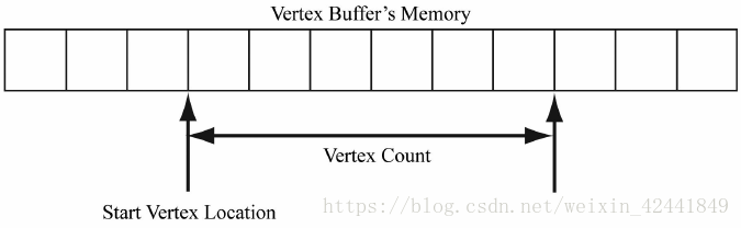
DrawInstanced方法中并没有指明拓扑结构,它由下面的方法中指定:
cmdList->IASetPrimitiveTopology(D3D_PRIMITIVE_TOPOLOGY_TRIANGLELIST);
3 目录和索引缓冲(INDEX BUFFERS)
和顶点一样,为了让GPU能访问到索引数据,我们需要创建一个索引缓冲和上传缓冲(Upload Buffer)。因为d3dUtil::CreateDefaultBuffer函数的数据是void*类型,所以可以直接使用它;为了绑定索引缓冲到渲染流水线,我们需要创建一个缓冲描述,和顶点一样,不需要描述堆;一个索引缓冲描述可以使用D3D12_INDEX_BUFFER_VIEW结构来表示:
typedef struct D3D12_INDEX_BUFFER_VIEW
{
	D3D12_GPU_VIRTUAL_ADDRESS BufferLocation;
	UINT SizeInBytes;
	DXGI_FORMAT Format;
} D3D12_INDEX_BUFFER_VIEW;
- BufferLocation:索引缓冲资源的虚拟地址,我们使用ID3D12Resource::GetGPUVirtualAddress来获取;
- SizeInBytes:从BufferLocation开始占用的字节数;
- Format:DXGI_FORMAT_R16_UINT或者DXGI_FORMAT_R32_UINT,正常情况下使用16位来减少内存和带宽,除非真的有需要使用32位;
和顶点一样,使用前需要绑定到流水线,可以使用ID3D12CommandList::SetIndexBuffer方法绑定到输入阶段:
std::uint16_t indices[] = {
	// front face
	0, 1, 2,
	0, 2, 3,
	// back face
	4, 6, 5,
	4, 7, 6,
	// left face
	4, 5, 1,
	4, 1, 0,
	// right face
	3, 2, 6,
	3, 6, 7,
	// top face
	1, 5, 6,
	1, 6, 2,
	// bottom face
	4, 0, 3,
	4, 3, 7
};

const UINT ibByteSize = 36 * sizeof(std::uint16_t);

ComPtr<ID3D12Resource> IndexBufferGPU = nullptr;
ComPtr<ID3D12Resource> IndexBufferUploader = nullptr;

IndexBufferGPU = d3dUtil::CreateDefaultBuffer(md3dDevice.Get(),
	mCommandList.Get(), indices), ibByteSize,
	IndexBufferUploader);

D3D12_INDEX_BUFFER_VIEW ibv;
ibv.BufferLocation = IndexBufferGPU->GetGPUVirtualAddress();
ibv.Format = DXGI_FORMAT_R16_UINT;
ibv.SizeInBytes = ibByteSize;
mCommandList->IASetIndexBuffer(&ibv);
最终使用索引的时候,我们需要使用ID3D12GraphicsCommandList::DrawIndexedInstanced方法,而不是DrawInstanced:
void ID3D12GraphicsCommandList::DrawIndexedInstanced(
	UINT IndexCountPerInstance,
	UINT InstanceCount,
	UINT StartIndexLocation,
	INT BaseVertexLocation,
	UINT StartInstanceLocation);
- IndexCountPerInstance:每个实例绘制的索引数量;
- InstanceCount:实例的数量,目前设置为1;
- StartIndexLocation:索引缓冲中开始索引的位置;
- BaseVertexLocation:当前绘制调用中,取得顶点时增加的一个整形值;
- StartInstanceLocation:用以后续实例Demo,当前只设置为0;
上述参数可以使用下面的例子来描述,比如现在有3个模型球体,盒子和一个圆柱体,它们拥有各自的顶点缓冲和索引缓冲;现在为了优化,将它们合并到一个全局的顶点缓冲和索引缓冲中,此时索引的值就错误了,需要重新计算:
这种情况下,绘制代码应该如下:
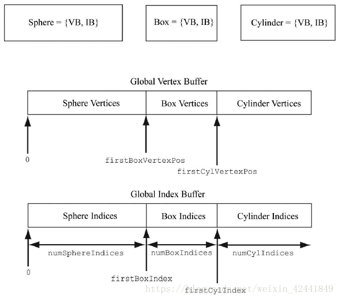
mCmdList->DrawIndexedInstanced( numSphereIndices, 1, 0, 0, 0);
mCmdList->DrawIndexedInstanced( numBoxIndices, 1, firstBoxIndex, firstBoxVertexPos, 0);
mCmdList->DrawIndexedInstanced( numCylIndices, 1, firstCylIndex, firstCylVertexPos, 0);
4 顶点着色器的例子
下面是一个简单的顶点着色器的代码:
cbuffer cbPerObject : register(b0)
{
	float4x4 gWorldViewProj;
};

void VS(float3 iPosL : POSITION,
	float4 iColor : COLOR,
	out float4 oPosH : SV_POSITION,
	out float4 oColor : COLOR)
{
	// Transform to homogeneous clip space.
	oPosH = mul(float4(iPosL, 1.0f), gWorldViewProj);

	// Just pass vertex color into the pixel shader.
	oColor = iColor;
}
函数名VS可以由我们任意定义,HLSL代码中不包含引用和指针,并且函数都是内敛的。
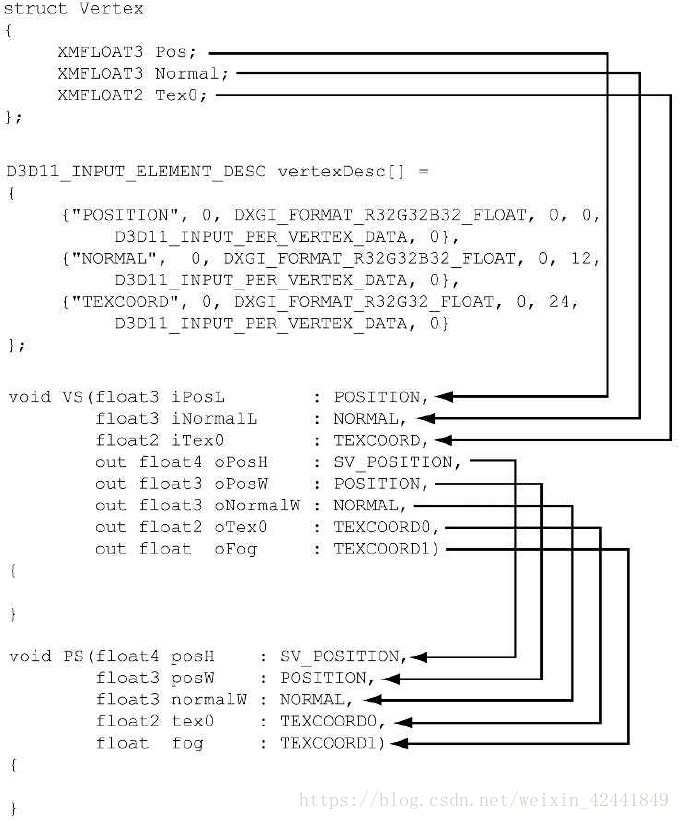
它的输入参数映射到之前我们在D3D12_INPUT_ELEMENT_DESC定义的顶点结构:
输出参数映射到下一节的像素着色器中,其中SV_POSITION语义中的SV表示系统值(system value),它表示在其次裁切空间中顶点的位置,所以它必须存在;其他不包含SV的可以不添加。
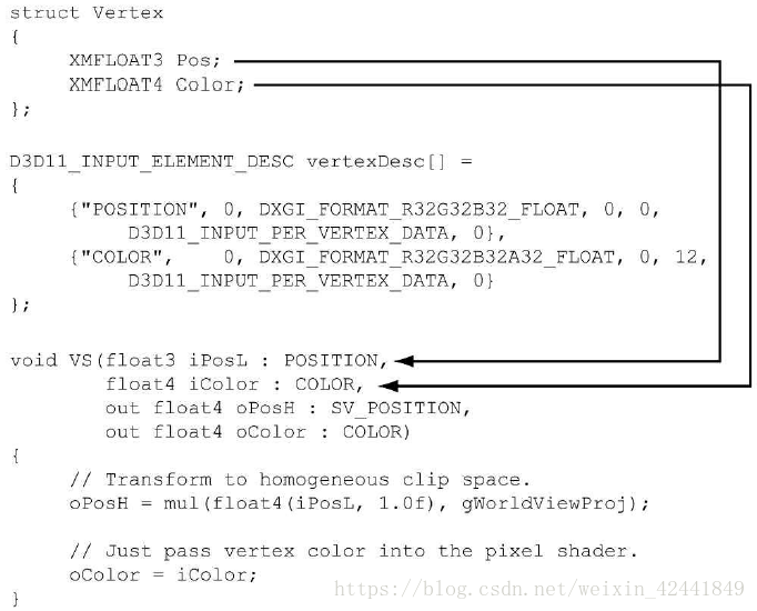
第一行代表将顶点通过乘以gWorldViewProj矩阵,从局部坐标系转换到其次裁切坐标系。
我们也可以使用结构体的形式,重写上面的代码:
cbuffer cbPerObject : register(b0)
{
	float4x4 gWorldViewProj;
};

struct VertexIn
{
	float3 PosL : POSITION;
	float4 Color : COLOR;
};

struct VertexOut
{
	float4 PosH : SV_POSITION;
	float4 Color : COLOR;
};

VertexOut VS(VertexIn vin)
{
	VertexOut vout;
	// Transform to homogeneous clip space.
	vout.PosH = mul(float4(vin.PosL, 1.0f), gWorldViewProj);

	// Just pass vertex color into the pixel shader.
	vout.Color = vin.Color;

	return vout;
}
如果没有几何着色器,SV_POSITION必须有;如果有几何着色器,SV_POSITION的值可以放在几何着色器中计算;
顶点着色器不做透视分割(perspective divide)处理,它只做透视矩阵相乘部分,透视分割后续由硬件完成。
4.1 输入布局描述(Input Layout Description)和输入签名链接(Input Signature Linking)
如果顶点着色器中的输入信号和顶点数据不匹配,将会报错,比如下面的代码:
//--------------
// C++ app code
//--------------
struct Vertex
{
	XMFLOAT3 Pos;
	XMFLOAT4 Color;
};
D3D12_INPUT_ELEMENT_DESC desc[] = {
	{"POSITION", 0, DXGI_FORMAT_R32G32B32_FLOAT, 0, 0, D3D12_INPUT_PER_VERTEX_DATA, 0},
	{"COLOR", 0, DXGI_FORMAT_R32G32B32A32_FLOAT, 0, 12, D3D12_INPUT_PER_VERTEX_DATA, 0}
};

//--------------
// Vertex shader
//--------------
struct VertexIn
{
	float3 PosL : POSITION;
	float4 Color : COLOR;
	float3 Normal : NORMAL;
};
struct VertexOut
{
	float4 PosH : SV_POSITION;
	float4 Color : COLOR;
};
VertexOut VS(VertexIn vin) { … }
到第9节的时候,我们将会看到,当创建ID3D12PipelineState时,我们需要同时指明输入布局描述和顶点着色器,Direct3D将会检查他们的兼容性。
顶点数据不需要和输入签名完全匹配,需要匹配的是,顶点数据需要提供顶点着色器所需要的所有数据;如果有更多顶点着色器不需要的数据是容许的,比如下面代码中的情况:
//--------------
// C++ app code
//--------------
struct Vertex
{
	XMFLOAT3 Pos;
	XMFLOAT4 Color;
	XMFLOAT3 Normal;
};

D3D12_INPUT_ELEMENT_DESC desc[] =
{
	{"POSITION", 0, DXGI_FORMAT_R32G32B32_FLOAT, 0, 0, D3D12_INPUT_PER_VERTEX_DATA, 0},
	{"COLOR", 0, DXGI_FORMAT_R32G32B32A32_FLOAT, 0, 12, D3D12_INPUT_PER_VERTEX_DATA, 0},
	{ "NORMAL", 0, DXGI_FORMAT_R32G32B32_FLOAT, 0, 28, D3D12_INPUT_PER_VERTEX_DATA, 0 }
};

//--------------
// Vertex shader
//--------------
struct VertexIn
{
	float3 PosL : POSITION;
	float4 Color : COLOR;
};

struct VertexOut
{
	float4 PosH : SV_POSITION;
	float4 Color : COLOR;
};

VertexOut VS(VertexIn vin) { … }
下面再考虑下如果顶点结构和输入签名在元素上相同,但是类型不同的情况:
//--------------
// C++ app code
//--------------
struct Vertex
{
	XMFLOAT3 Pos;
	XMFLOAT4 Color;
};

D3D12_INPUT_ELEMENT_DESC desc[] =
{
	{"POSITION", 0, DXGI_FORMAT_R32G32B32_FLOAT, 0, 0, D3D12_INPUT_PER_VERTEX_DATA, 0},
	{"COLOR", 0, DXGI_FORMAT_R32G32B32A32_FLOAT, 0, 12, D3D12_INPUT_PER_VERTEX_DATA, 0}
};

//--------------
// Vertex shader
//--------------
struct VertexIn
{
	float3 PosL : POSITION;
	int4 Color : COLOR;
};

struct VertexOut
{
	float4 PosH : SV_POSITION;
	float4 Color : COLOR;
};

VertexOut VS(VertexIn vin) { … }
这种情况是合法的,因为Direct3D容许字节在输入寄存器中被重新解释,但是VC++会提示警告:
	D3D12 WARNING: ID3D11Device::CreateInputLayout:
The provided input signature expects to read an
element with SemanticName/Index: ‘COLOR’/0 and
component(s) of the type ‘int32’. However, the
matching entry in the Input Layout declaration,
element[1], specifies mismatched format:
‘R32G32B32A32_FLOAT’. This is not an error, since
behavior is well defined: The element format
determines what data conversion algorithm gets
applied before it shows up in a shader register.
Independently, the shader input signature defines
how the shader will interpret the data that has
been placed in its input registers, with no change
in the bits stored. It is valid for the application
to reinterpret data as a different type once it is
in the vertex shader, so this warning is issued
just in case reinterpretation was not intended by
the author.
5 像素着色器的例子
通过顶点着色器输出的顶点属性会基于三角形进行差值产生新属性,然后会输入的像素着色器中:
像素着色器的职责是计算每一个像素片段的颜色,需要注意的是,不是每个像素都可以被写入后置缓冲(back buffer),它可能在像素着色器中被裁切(使用HLSL的Clip函数),或者被其他深度更小的像素片段阻塞,或者在后续的阶段,比如模板测试中被废弃。所以后置缓冲中的每个像素可能会有多个候选者,这个是和我们通常意义上的像素的区别。
对于硬件优化,一个像素片段是有可能直接跳过像素着色器,比如(early-z rejection),但是在有些情况下,这个功能会无法使用,比如如果像素着色器中修改了Z值,那么每个像素必须进行像素着色器计算后才能得到最终的Z值。
下面的代码是像素着色器的一个例子:
cbuffer cbPerObject : register(b0)
{
	float4x4 gWorldViewProj;
};

void VS(float3 iPos : POSITION,
	float4 iColor : COLOR,
	out float4 oPosH : SV_POSITION,
	out float4 oColor : COLOR)
{
	// Transform to homogeneous clip space.
	oPosH = mul(float4(iPos, 1.0f), gWorldViewProj);
	// Just pass vertex color into the pixel shader.
	oColor = iColor;
}

float4 PS(float4 posH : SV_POSITION, float4 color : COLOR) : SV_Target
{
	return pin.Color;
}
像素着色器输入的参数必须完全匹配顶点着色器输出的参数,这个是要求;返回的是一个4D颜色值,该值必须匹配渲染目标格式。同样也可以使用结构体的方式重写上面的代码:
cbuffer cbPerObject : register(b0)
{
	float4x4 gWorldViewProj;
};

struct VertexIn
{
	float3 Pos : POSITION;
	float4 Color : COLOR;
};

struct VertexOut
{
	float4 PosH : SV_POSITION;
	float4 Color : COLOR;
};

VertexOut VS(VertexIn vin)
{
	VertexOut vout;
	// Transform to homogeneous clip space.
	vout.PosH = mul(float4(vin.Pos, 1.0f), gWorldViewProj);

	// Just pass vertex color into the pixel shader.
	vout.Color = vin.Color;

	return vout;
}

float4 PS(VertexOut pin) : SV_Target
{
	return pin.Color;
}
6 常量缓冲(CONSTANT BUFFERS)
6.1 创建常量缓冲
常量缓冲是GPU资源(ID3D12Resource)的一种,它的数据内容可以被着色器程序引用。在第4节中的示例代码:
cbuffer cbPerObject : register(b0)
{
	float4x4 gWorldViewProj;
};
就引用了一个叫cbPerObject的cbuffer类型的对象。和顶点缓冲和像素缓冲不同的是,常量缓冲一般每帧只被CPU更新一次,比如摄像机位置改变后,我们需要更新变换矩阵;所以我们将以上传堆的方式创建常量缓冲,这样它就可以被CPU更新。
常量缓冲也有硬件要求,它的大小必须是硬件最小申请大小的倍数(256 bytes)。
我们经常也需要对个类型相同的常量缓冲,下面的代码展示了如何创建多个(NumElements)常量缓冲:
struct ObjectConstants
{
	DirectX::XMFLOAT4X4 WorldViewProj = MathHelper::Identity4x4();
};

UINT elementByteSize = d3dUtil::CalcConstantBufferByteSize(sizeof(ObjectConstants));
ComPtr<ID3D12Resource> mUploadCBuffer;

device->CreateCommittedResource(
	&CD3DX12_HEAP_PROPERTIES(D3D12_HEAP_TYPE_UPLOAD),
	D3D12_HEAP_FLAG_NONE,
	&CD3DX12_RESOURCE_DESC::Buffer(mElementByteSize* NumElements),
	D3D12_RESOURCE_STATE_GENERIC_READ,
	nullptr,
	IID_PPV_ARGS(&mUploadCBuffer));
我们可以认为mUploadCBuffer是保存了ObjectConstants类型常量缓冲的数组(填充到256字节的倍数)。当需要绘制物体的时候,我只需要绑定一个常量缓冲描述(CBV)来划分出当前物体对应的区域。本书中我们经常会把保存了一个数组常量缓冲的mUploadCBuffer称之为常量缓冲。
d3dUtil::CalcConstantBufferByteSize方法用以计算填充到256字节倍数的大小:
UINT d3dUtil::CalcConstantBufferByteSize(UINT byteSize)
{
	// Constant buffers must be a multiple of the minimum hardware
	// allocation size (usually 256 bytes). So round up to nearest
	// multiple of 256. We do this by adding 255 and then masking off
	// the lower 2 bytes which store all bits < 256.

	// Example: Suppose byteSize = 300.
	// (300 + 255) & ˜255
	// 555 & ˜255
	// 0x022B & ˜0x00ff
	// 0x022B & 0xff00
	// 0x0200
	// 512
	return (byteSize + 255) & ˜255;
}
虽然我们这里做了处理(256字节倍数),但是在HLSL中这并不是必须的,因为会HLSL会做隐式处理。
// Implicitly padded to 256 bytes.
cbuffer cbPerObject : register(b0)
{
	float4x4 gWorldViewProj;
};

// Explicitly padded to 256 bytes.
cbuffer cbPerObject : register(b0)
{
	float4x4 gWorldViewProj;
	float4x4 Pad0;
	float4x4 Pad1;
	float4x4 Pad1;
};
为了避免常量缓冲隐式对齐,我们最好做到显示对齐。
Direct3D引进了着色模型(shader model)5.1,该模型引进了一个可选的HLSL标识来定义常量缓冲:
struct ObjectConstants
{
	float4x4 gWorldViewProj;
	uint matIndex;
};

ConstantBuffer<ObjectConstants> gObjConstants :
register(b0);
这里常量缓冲的数据元素是分开定义的,然后常量缓冲根据结构来创建。那么在着色器中常量缓冲的数据可以这样访问:
uint index = gObjConstants.matIndex;
6.2 更新常量缓冲
因为常量缓冲是由D3D12_HEAP_TYPE_UPLOAD堆类型创建的,所以我们可以通过CPU来更新资源。我们可以通过Map函数来获取资源的指针:
ComPtr<ID3D12Resource> mUploadBuffer;
BYTE* mMappedData = nullptr;
mUploadBuffer->Map(0, nullptr, reinterpret_cast<void**>(&mMappedData));
第一个参数子资源的序号,因为在缓冲中,我们只有一个资源,所以设置为0;第二个参数是一个可选的指向D3D12_RANGE的指针,它用来定义映射的内存的范围,设置为Null代表全部;第三个参数返回映射的数据的指针。如果要复制数据进去,可以这样调用:
memcpy(mMappedData, &data, dataSizeInBytes);
当我们处理完毕,我们需要在释放之前调用Unmap方法:
if(mUploadBuffer != nullptr)
	mUploadBuffer->Unmap(0, nullptr);

mMappedData = nullptr;
第一个参数是子资源的序号,对于缓冲直接设置为0;第二个参数是指向D3D12_RANGE结构的指针,设置为Null代表所有资源范围;
6.3 上传缓冲助手
我们定义一个UploadBuffer.h来简单的封装一下上传缓冲,它包含构造和析构;对资源的映射和取消映射;和CopyData方法(用以在CPU对数据进行修改)。值得注意的是,该类不仅仅用于常量缓冲,可以适用于任意上传缓冲。如果是使用于常量缓冲,我们需要设置isConstantBuffer值,因为常量缓冲的数据需要对齐到256字节的倍数。
template<typename T>
class UploadBuffer
{
public:
	UploadBuffer(ID3D12Device* device, UINT elementCount, bool isConstantBuffer) :
		mIsConstantBuffer(isConstantBuffer)
	{
		mElementByteSize = sizeof(T);
		// Constant buffer elements need to be multiples of 256 bytes.
		// This is because the hardware can only view constant data
		// at m*256 byte offsets and of n*256 byte lengths.
		// typedef struct D3D12_CONSTANT_BUFFER_VIEW_DESC {
			// UINT64 OffsetInBytes; // multiple of 256
			// UINT SizeInBytes; // multiple of 256
			// } D3D12_CONSTANT_BUFFER_VIEW_DESC;

		if(isConstantBuffer)
			mElementByteSize = d3dUtil::CalcConstantBufferByteSize(sizeof(T));

		ThrowIfFailed(device->CreateCommittedResource(
			&CD3DX12_HEAP_PROPERTIES(D3D12_HEAP_TYPE_UPLOAD),
			D3D12_HEAP_FLAG_NONE,
			&CD3DX12_RESOURCE_DESC::Buffer(mElementByteSize*elementCount),
			D3D12_RESOURCE_STATE_GENERIC_READ,
			nullptr,
			IID_PPV_ARGS(&mUploadBuffer)));

		ThrowIfFailed(mUploadBuffer->Map(0, nullptr, reinterpret_cast<void**>(&mMappedData)));

		// We do not need to unmap until we are done with the resource.
		// However, we must not write to the resource while it is in use by
		// the GPU (so we must use synchronization techniques).
	}

	UploadBuffer(const UploadBuffer& rhs) = delete;
	UploadBuffer& operator=(const UploadBuffer& rhs) = delete;
	˜UploadBuffer()
	{
		if(mUploadBuffer != nullptr)
			mUploadBuffer->Unmap(0, nullptr);

		mMappedData = nullptr;
	}

	ID3D12Resource* Resource()const
	{
		return mUploadBuffer.Get();
	}

	void CopyData(int elementIndex, const T& data)
	{
		memcpy(&mMappedData[elementIndex*mElementByteSize], &data, sizeof(T));
	}

private:
	Microsoft::WRL::ComPtr<ID3D12Resource> mUploadBuffer;
	BYTE* mMappedData = nullptr;
	UINT mElementByteSize = 0;
	bool mIsConstantBuffer = false;
};
比如,当物体做运动/旋转/缩放时需要改变世界变换矩阵;当摄像机移动/旋转时需要改变视图变换矩阵;当窗口尺寸变化时需要改变透视投影矩阵需要改变。所以本章的Demo中,我们在Update函数中更新:
void BoxApp::OnMouseMove(WPARAM btnState, int x, int y)
{
	if((btnState & MK_LBUTTON) != 0)
	{
		// Make each pixel correspond to a quarter of a degree.
		float dx = XMConvertToRadians(0.25f*static_cast<float> (x - mLastMousePos.x));
		float dy = XMConvertToRadians(0.25f*static_cast<float> (y - mLastMousePos.y));

		// Update angles based on input to orbit
		camera around box.
		mTheta += dx;
		mPhi += dy;

		// Restrict the angle mPhi.
		mPhi = MathHelper::Clamp(mPhi, 0.1f, MathHelper::Pi - 0.1f);
	}
	else if((btnState & MK_RBUTTON) != 0)
	{
		// Make each pixel correspond to 0.005 unit in the scene.
		float dx = 0.005f*static_cast<float>(x - mLastMousePos.x);
		float dy = 0.005f*static_cast<float>(y - mLastMousePos.y);

		// Update the camera radius based on input.
		mRadius += dx - dy;

		// Restrict the radius.
		mRadius = MathHelper::Clamp(mRadius, 3.0f, 15.0f);
	}

	mLastMousePos.x = x;
	mLastMousePos.y = y;
}

void BoxApp::Update(const GameTimer& gt)
{
	// Convert Spherical to Cartesian coordinates.
	float x = mRadius*sinf(mPhi)*cosf(mTheta);
	float z = mRadius*sinf(mPhi)*sinf(mTheta);
	float y = mRadius*cosf(mPhi);

	// Build the view matrix.
	XMVECTOR pos = XMVectorSet(x, y, z, 1.0f);
	XMVECTOR target = XMVectorZero();
	XMVECTOR up = XMVectorSet(0.0f, 1.0f, 0.0f, 0.0f);
	XMMATRIX view = XMMatrixLookAtLH(pos, target, up);
	XMStoreFloat4x4(&mView, view);
	XMMATRIX world = XMLoadFloat4x4(&mWorld);
	XMMATRIX proj = XMLoadFloat4x4(&mProj);
	XMMATRIX worldViewProj = world*view*proj;

	// Update the constant buffer with the latest worldViewProj matrix.
	ObjectConstants objConstants;
	XMStoreFloat4x4(&objConstants.WorldViewProj, XMMatrixTranspose(mObjectCB->CopyData(0, objConstants);
}
6.4 常量缓冲描述(Constant Buffer Descriptors)
我们需要一个描述来将常量缓冲绑定到渲染流水线,它需要使用D3D12_DESCRIPTOR_HEAP_TYPE_CBV_SRV_UAV 描述堆类型,该类型可以混合保存常量缓冲(CBV),着色器资源(SRV)和无序访问描述(UAV:unordered access descriptors),所以需要创建一个该类型的堆:
D3D12_DESCRIPTOR_HEAP_DESC cbvHeapDesc;
cbvHeapDesc.NumDescriptors = 1;
cbvHeapDesc.Type = D3D12_DESCRIPTOR_HEAP_TYPE_CBV_SRV_UAV;
cbvHeapDesc.Flags = D3D12_DESCRIPTOR_HEAP_FLAG_SHADER_VISIBLE;
cbvHeapDesc.NodeMask = 0;

ComPtr<ID3D12DescriptorHeap> mCbvHeap

md3dDevice->CreateDescriptorHeap(&cbvHeapDesc,
	IID_PPV_ARGS(&mCbvHeap));
在本章的Demo中,我们没有SRV和UAV,并且我们只绘制一个物体,所以我们只需要一个描述;
一个CBV通过填充一个D3D12_CONSTANT_BUFFER_VIEW_DESC结构的实例,调用ID3D12Device::CreateConstantBufferView方法来创建:
// Constant data per-object.
struct ObjectConstants
{
	XMFLOAT4X4 WorldViewProj = MathHelper::Identity4x4();
};

// Constant buffer to store the constants of n object.
std::unique_ptr<UploadBuffer<ObjectConstants>> mObjectCB = nullptr;
mObjectCB = std::make_unique<UploadBuffer<ObjectConstants>>( md3dDevice.Get(), n, true);
UINT objCBByteSize = d3dUtil::CalcConstantBufferByteSize(sizeof(ObjectConstants));

// Address to start of the buffer (0th constant buffer).
D3D12_GPU_VIRTUAL_ADDRESS cbAddress = mObjectCB->Resource()->GetGPUVirtualAddress();

// Offset to the ith object constant buffer in the buffer.
int boxCBufIndex = i;
cbAddress += boxCBufIndex*objCBByteSize;

D3D12_CONSTANT_BUFFER_VIEW_DESC cbvDesc;
cbvDesc.BufferLocation = cbAddress;
cbvDesc.SizeInBytes = d3dUtil::CalcConstantBufferByteSize(sizeof(ObjectConstants));

md3dDevice->CreateConstantBufferView(
	&cbvDesc,
	mCbvHeap->GetCPUDescriptorHandleForHeapStart());
D3D12_CONSTANT_BUFFER_VIEW_DESC结构描述了常量缓冲中绑定到HLSL中的一个自区间;根据硬件的要求BufferLocation和SizeInBytes需要是256的倍数;所以如果你设置为64,会收到下面的报错:
D3D12 ERROR:
ID3D12Device::CreateConstantBufferView: SizeInBytes
of 64 is invalid. Device requires SizeInBytes be a
multiple of 256.
D3D12 ERROR: ID3D12Device::
CreateConstantBufferView: OffsetInBytes of 64 is
invalid. Device requires OffsetInBytes be a
multiple of 256.
6.5 根签名(Root Signature)和描述表(Descriptor Tables)
一般情况下,在执行绘制命令之前,不同的着色器程序希望绑定不同的资源到绘制管线中;资源绑定在着色器可以访问到的对应的寄存器槽中:
// Texture resource bound to texture register slot 0.
Texture2D gDiffuseMap : register(t0);

// Sampler resources bound to sampler register slots 0-5.
SamplerState gsamPointWrap : register(s0);
SamplerState gsamPointClamp : register(s1);
SamplerState gsamLinearWrap : register(s2);
SamplerState gsamLinearClamp : register(s3);
SamplerState gsamAnisotropicWrap : register(s4);
SamplerState gsamAnisotropicClamp : register(s5);

// cbuffer resource bound to cbuffer register slots 0-2
cbuffer cbPerObject : register(b0)
{
	float4x4 gWorld;
	float4x4 gTexTransform;
};

// Constant data that varies per material.
cbuffer cbPass : register(b1)
{
	float4x4 gView;
	float4x4 gProj;
	[…] // Other fields omitted for brevity.
};

cbuffer cbMaterial : register(b2)
{
	float4 gDiffuseAlbedo;
	float3 gFresnelR0;
	float gRoughness;
	float4x4 gMatTransform;
};
根签名定义了那些资源将要绑定到渲染管线,和从哪里映射到着色器程序;不同的绘制调用可能使用不同的着色器程序,也就需要不同的根签名。
一个根签名在Direct3D中由ID3D12RootSignature接口表示。它由着色器程序需要的参数数组定义。一个根参数(root parameter)可以是一个根常量(root constant),根描述(root descriptor)或者描述表(descriptor table)。本章中我们只使用描述表,一个描述表定义了一段在描述堆中连续的描述。
下面的代码创建了一个具有一个由足够大的保存一个CBV的描述表的根参数的根信号:
// Root parameter can be a table, root descriptor or root constants.
CD3DX12_ROOT_PARAMETER slotRootParameter[1];

// Create a single descriptor table of CBVs.
CD3DX12_DESCRIPTOR_RANGE cbvTable;
cbvTable.Init(
	D3D12_DESCRIPTOR_RANGE_TYPE_CBV,
	1, // Number of descriptors in table
	339
	0);// base shader register arguments are bound to for this root parameter

slotRootParameter[0].InitAsDescriptorTable(
	1, // Number of ranges
	&cbvTable); // Pointer to array of ranges

// A root signature is an array of root parameters.
CD3DX12_ROOT_SIGNATURE_DESC rootSigDesc(1,
slotRootParameter, 0, nullptr,
D3D12_ROOT_SIGNATURE_FLAG_ALLOW_INPUT_ASSEMBLER_INPUT_// create a root signature with a single slot
which points to a

// descriptor range consisting of a single constant buffer.
ComPtr<ID3DBlob> serializedRootSig = nullptr;
ComPtr<ID3DBlob> errorBlob = nullptr;
HRESULT hr = D3D12SerializeRootSignature(&rootSigDesc,
	D3D_ROOT_SIGNATURE_VERSION_1,
	serializedRootSig.GetAddressOf(),
	errorBlob.GetAddressOf());

ThrowIfFailed(md3dDevice->CreateRootSignature(
	0,
	serializedRootSig->GetBufferPointer(),
	serializedRootSig->GetBufferSize(),
	IID_PPV_ARGS(&mRootSignature)));
我们将会在下节中更多的描述CD3DX12_ROOT_PARAMETER和CD3DX12_DESCRIPTOR_RANGE,目前只需要了解下面的代码:
CD3DX12_ROOT_PARAMETER slotRootParameter[1];
CD3DX12_DESCRIPTOR_RANGE cbvTable;

cbvTable.Init(
	D3D12_DESCRIPTOR_RANGE_TYPE_CBV, // table type
	1, // Number of descriptors in table
	0);// base shader register arguments are bound to for this root parameter

slotRootParameter[0].InitAsDescriptorTable(
	1, // Number of ranges
	&cbvTable); // Pointer to array of ranges
一个根签名只是 定义了那些资源要被绑定到渲染流水线中,但是它并不真正执行绑定工作,我们需要调用ID3D12GraphicsCommandList::SetGraphicsRootDescriptorTab方法:
void ID3D12GraphicsCommandList::SetGraphicsRootDescriptorTable(
	UINT RootParameterIndex,
	D3D12_GPU_DESCRIPTOR_HANDLE BaseDescriptor);
- RootParameterIndex:根参数的索引;
- BaseDescriptor:描述表中的第一个描述;
下面的代码设置根签名和CBV堆到命令列表,然后设置描述表初始化我们要绑定的资源:
mCommandList->SetGraphicsRootSignature(mRootSignature.Get());
ID3D12DescriptorHeap* descriptorHeaps[] = {
	mCbvHeap.Get() };

mCommandList->SetDescriptorHeaps(_countof(descriptorHeaps),
	descriptorHeaps);

// Offset the CBV we want to use for this draw call.
CD3DX12_GPU_DESCRIPTOR_HANDLE cbv(mCbvHeap ->GetGPUDescriptorHandleForHeapStart());
cbv.Offset(cbvIndex, mCbvSrvUavDescriptorSize);
mCommandList->SetGraphicsRootDescriptorTable(0, cbv);
出于性能考虑,根签名要尽可能小,并且在每帧中尽可能减少切换根签名的次数。
7 编译着色器代码
在Direct3D中,着色器代码首先需要编译成可移植的字节码,然后图形驱动会将这些字节码针对本机的GPU结构进行再次编译和优化。在运行时,我们可以使用下面的函数进行编译:
HRESULT D3DCompileFromFile(
	LPCWSTR pFileName,
	const D3D_SHADER_MACRO *pDefines,
	ID3DInclude *pInclude,
	LPCSTR pEntrypoint,
	LPCSTR pTarget,
	UINT Flags1,
	UINT Flags2,
	ID3DBlob **ppCode,
	ID3DBlob **ppErrorMsgs);
- pFileName:hlsl文件的名称;
- pDefines:本书中不使用,直接设置为Null,具体功能可以查看文档;
- pInclude:本书中不使用,直接设置为null,具体功能可以查看文档;
- pEntrypoint:着色器程序入口函数名称;
- pTarget:一个指明着色器程序类型和版本的字符串,本书中使用5.0或者5.1:
			a) vs_5_0 and vs_5_1: Vertex shader 5.0 and 5.1, respectively.
			b) hs_5_0 and hs_5_1: Hull shader 5.0 and 5.1, respectively.
			c) ds_5_0 and ds_5_1: Domain shader 5.0 and 5.1, respectively.
			d) gs_5_0 and gs_5_1: Geometry shader 5.0 and 5.1, respectively.
			e) ps_5_0 and ps_5_1: Pixel shader 5.0 and 5.1, respectively.
			f) cs_5_0 and cs_5_1: Compute shader 5.0 and 5.1, respectively.
- Flags1:指明着色器程序如何被编译的标记,本书中只使用下面的2个:
			a) D3DCOMPILE_DEBUG: Compiles the shaders in debug mode.
			b) D3DCOMPILE_SKIP_OPTIMIZATION: Instructs the compiler to skip optimizations (useful for debugging).
- Flags2:本书中不使用,具体功能查看文档;
- ppCode:返回保存了编译完成的数据ID3DBlob结构的指针;
- ppErrorMsgs:返回保存了如果有错误信息的ID3DBlob结构的指针;
ID3DBlob只是一个包含了2个函数的内存块:
- LPVOID GetBufferPointer:返回数据的void*,所以在使用前必须转换为适当的类型;
- SIZE_T GetBufferSize:返回数据的大小;
为了支持错误输出,我们在d3dUtil.h/.cpp中定义了下面的帮助函数:
ComPtr<ID3DBlob> d3dUtil::CompileShader(
	const std::wstring& filename,
	const D3D_SHADER_MACRO* defines,
	const std::string& entrypoint,
	const std::string& target)
{
	// Use debug flags in debug mode.
	UINT compileFlags = 0;

	#if defined(DEBUG) || defined(_DEBUG)
		compileFlags = D3DCOMPILE_DEBUG | D3DCOMPILE_SKIP_OPTIMIZATION;
	#endif

	HRESULT hr = S_OK;
	ComPtr<ID3DBlob> byteCode = nullptr;
	ComPtr<ID3DBlob> errors;

	hr = D3DCompileFromFile(filename.c_str(),
		defines, D3D_COMPILE_STANDARD_FILE_INCLUDE,
		entrypoint.c_str(), target.c_str(),
		compileFlags, 0, &byteCode, &errors);

	// Output errors to debug window.
	if(errors != nullptr)
		OutputDebugStringA((char*)errors->GetBufferPointer());

	ThrowIfFailed(hr);
	return byteCode;
}

//Here is an example of calling this function:
ComPtr<ID3DBlob> mvsByteCode = nullptr;
ComPtr<ID3DBlob> mpsByteCode = nullptr;

mvsByteCode = d3dUtil::CompileShader(L"Shaders\\color.hlsl", nullptr, "VS", "vs_5_0");
mpsByteCode = d3dUtil::CompileShader(L"Shaders\\color.hlsl", nullptr, "PS", "ps_5_0");
编译着色器代码并没有把着色器绑定到渲染流水线,绑定工作将在第九节中描述。
7.1 离线编译
使用离线编译的好处:
- 编译已经完成的着色器代码可能会占用大量时间;
- 可以更早的,更方便的查看编译产生的错误;
- Window 8的应用必须使用离线编译。
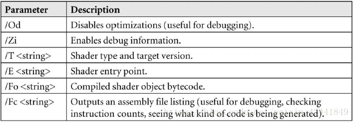
通常对编译好的着色器文件使用.cso(compiled shader object)扩展名;我们使用DirectX附带的命令行工具FXC tool,对于包含VS和PS入口函数的color.hlsl代码,如果要编译调试版本:
fxc "color.hlsl" /Od /Zi /T vs_5_0 /E "VS" /Fo "color_vs.cso" /Fc "color_vs.asm"
fxc "color.hlsl" /Od /Zi /T ps_5_0 /E "PS" /Fo "color_ps.cso" /Fc "color_ps.asm"
如果要编译发布版本:
fxc "color.hlsl" /T vs_5_0 /E "VS" /Fo "color_vs.cso" /Fc "color_vs.asm"
fxc "color.hlsl" /T ps_5_0 /E "PS" /Fo "color_ps.cso" /Fc "color_ps.asm"
编译完成后,我们还需要加载文件,可以使用C++问价输入机制:
ComPtr<ID3DBlob> d3dUtil::LoadBinary(const std::wstring& filename)
{
	std::ifstream fin(filename, std::ios::binary);
	fin.seekg(0, std::ios_base::end);

	std::ifstream::pos_type size = (int)fin.tellg();
	fin.seekg(0, std::ios_base::beg);

	ComPtr<ID3DBlob> blob;
	ThrowIfFailed(D3DCreateBlob(size,
		blob.GetAddressOf()));
		fin.read((char*)blob->GetBufferPointer(),
		size);

	fin.close();
	return blob;
}…

ComPtr<ID3DBlob> mvsByteCode = d3dUtil::LoadBinary(L"Shaders\\color_vs.cso");
ComPtr<ID3DBlob> mpsByteCode = d3dUtil::LoadBinary(L"Shaders\\color_ps.cso");
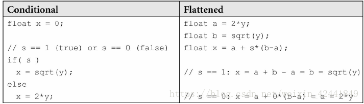
7.2 生成汇编代码
/Fc选项参数可以让FXC生成汇编代码,观察着色器的汇编代码可以查看指令数和确认被生成的是哪类代码,有些时候和你所预期的会不太一样。比如说在你的HLSL代码中有个条件语句,你就希望在汇编代码中有一个分支;但是在早期的可编程GPU上,分支运算非常耗时,所以有时编译器会在条件语句中评估每个分支,然后插入语句选择正确的选项,就像下面的代码一样:
所以flattened函数给我们一个没有分支的相同结果,但是如果不查看汇编代码,我们无法知道是否已经flattened处理过。所以有时你需要查看汇编代码来确认具体发生了什么,下面就是一个color.hlsl的例子:
//
// Generated by Microsoft (R) HLSL Shader Compiler 6.4.9844.0
//
//
// Buffer Definitions:
//
// cbuffer cbPerObject
// {
//
// float4x4 gWorldViewProj; // Offset: 0 Size: 64
//
// }
//
//
// Resource Bindings:
//
// Name Type Format Dim Slot Elements
// ------------------------------ ---------- ---- --- ----------- ---- ---------
// cbPerObject cbuffer NA NA 0 1
//
//
//
// Input signature:
//
// Name Index Mask Register SysValue Format Used
// -------------------- ----- ------ -------- ---
----- ------- ------
// POSITION 0 xyz 0 NONE float xyz
// COLOR 0 xyzw 1 NONE float xyzw
//
//
// Output signature:
//
// Name Index Mask Register SysValue Format Used
// -------------------- ----- ------ -------- --- ----- ------- ------
// SV_POSITION 0 xyzw 0 POS float xyzw
// COLOR 0 xyzw 1 NONE float xyzw
//
vs_5_0
dcl_globalFlags refactoringAllowed |
skipOptimization
dcl_constantbuffer cb0[4], immediateIndexed
dcl_input v0.xyz
dcl_input v1.xyzw
dcl_output_siv o0.xyzw, position
dcl_output o1.xyzw
dcl_temps 2
//
// Initial variable locations:
// v0.x <- vin.PosL.x; v0.y <- vin.PosL.y; v0.z <- vin.PosL.z;
// v1.x <- vin.Color.x; v1.y <- vin.Color.y; v1.z <- vin.Color.z; v1.w <- vin.Color.w;
// o1.x <- <VS return value>.Color.x;
// o1.y <- <VS return value>.Color.y;
// o1.z <- <VS return value>.Color.z;
// o1.w <- <VS return value>.Color.w;
// o0.x <- <VS return value>.PosH.x;
// o0.y <- <VS return value>.PosH.y;
// o0.z <- <VS return value>.PosH.z;
// o0.w <- <VS return value>.PosH.w
//
#line 29 "color.hlsl"
mov r0.xyz, v0.xyzx
mov r0.w, l(1.000000)
dp4 r1.x, r0.xyzw, cb0[0].xyzw // r1.x <- vout.PosH.x
dp4 r1.y, r0.xyzw, cb0[1].xyzw // r1.y <- vout.PosH.y
dp4 r1.z, r0.xyzw, cb0[2].xyzw // r1.z <- vout.PosH.z
dp4 r1.w, r0.xyzw, cb0[3].xyzw // r1.w <- vout.PosH.w
#line 32
mov r0.xyzw, v1.xyzw // r0.x <- vout.Color.x;
r0.y <- vout.Color.y;
// r0.z <- vout.Color.z; r0.w <- vout.Color.w
mov o0.xyzw, r1.xyzw
mov o1.xyzw, r0.xyzw
ret
// Approximately 10 instruction slots used
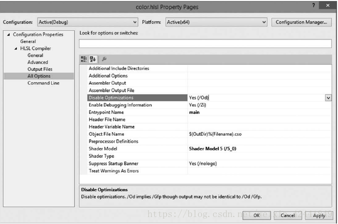
7.3 使用Visual Studio离线编译着色器
VS2013以后对着色器的编译有了完整的支持,你可以直接添加.hlsl文件到工程,然后VS将会识别和提供编译相关的选项,这些选项允许在UI界面下设置FXC参数:
但是在VS下编译着色器程序,每个文件只能支持一个着色器程序,这代表不能讲VS和PS同时放在一个文件里(所以一般不会使用它)。
8 光栅化阶段
光栅化阶段由D3D12_RASTERIZER_DESC结构进行配置;该阶段它不可编程,只能配置:
typedef struct D3D12_RASTERIZER_DESC {
	D3D12_FILL_MODE FillMode; // Default: D3D12_FILL_SOLID
	D3D12_CULL_MODE CullMode; // Default: D3D12_CULL_BACK
	BOOL FrontCounterClockwise; // Default: false
	INT DepthBias; // Default: 0
	FLOAT DepthBiasClamp; // Default: 0.0f
	FLOAT SlopeScaledDepthBias; // Default: 0.0f
	BOOL DepthClipEnable; // Default: true
	BOOL ScissorEnable; // Default: false
	BOOL MultisampleEnable; // Default: false
	BOOL AntialiasedLineEnable; // Default: false
	UINT ForcedSampleCount; // Default: 0

	// Default: D3D12_CONSERVATIVE_RASTERIZATION_MODE_OFF
	D3D12_CONSERVATIVE_RASTERIZATION_MODE ConservativeRaster;
	} D3D12_RASTERIZER_DESC;
其中大部分参数都不经常使用,本章只介绍4个,其他参数建议查看官方文档仔细阅读:
- FillMode:D3D12_FILL_WIREFRAME线框渲染模式;D3D12_FILL_SOLID实体渲染模式;
- CullMode:D3D12_CULL_NONE禁用裁切;D3D12_CULL_BACK背面裁切三角形;D3D12_CULL_FRONT正面裁切三角形;背面裁切是默认值;
- FrontCounterClockwise:false代表三角形顺时针方向为前向,true相反;
- ScissorEnable:设置true开启scissor test,false禁用,其中false是默认值。
下面是创建的一个代码例子:
CD3DX12_RASTERIZER_DESC rsDesc(D3D12_DEFAULT);
rsDesc.FillMode = D3D12_FILL_WIREFRAME;
rsDesc.CullMode = D3D12_CULL_NONE;
CD3DX12_RASTERIZER_DESC是继承自D3D12_RASTERIZER_DESC的一个非常方便好用的类,它添加了一些帮助的构造函数。CD3D12_DEFAULT 和 D3D12_DEFAULT定义类似于:
struct CD3D12_DEFAULT {};
extern const DECLSPEC_SELECTANY CD3D12_DEFAULT D3D12_DEFAULT;
9 流水线状态对象(PIPELINE STATE OBJECT:PSO)
一个流水线状态对象(PSO)由一个ID3D12PipelineState接口表示,为了创建它,我们需要先填充一个D3D12_GRAPHICS_PIPELINE_STATE_DESC实例:
typedef struct D3D12_GRAPHICS_PIPELINE_STATE_DESC
{
	ID3D12RootSignature *pRootSignature;
	D3D12_SHADER_BYTECODE VS;
	D3D12_SHADER_BYTECODE PS;
	D3D12_SHADER_BYTECODE DS;
	D3D12_SHADER_BYTECODE HS;
	D3D12_SHADER_BYTECODE GS;
	D3D12_STREAM_OUTPUT_DESC StreamOutput;
	D3D12_BLEND_DESC BlendState;
	UINT SampleMask;
	D3D12_RASTERIZER_DESC RasterizerState;
	D3D12_DEPTH_STENCIL_DESC DepthStencilState;
	D3D12_INPUT_LAYOUT_DESC InputLayout;
	D3D12_PRIMITIVE_TOPOLOGY_TYPE PrimitiveTopologyType;
	UINT NumRenderTargets;
	DXGI_FORMAT RTVFormats[8];
	DXGI_FORMAT DSVFormat;
	DXGI_SAMPLE_DESC SampleDesc;
} D3D12_GRAPHICS_PIPELINE_STATE_DESC;
- pRootSignature:指向根签名的指针;
- VS:需要绑定的顶点种色器,由D3D12_SHADER_BYTECODE结构来定义
		typedef struct D3D12_SHADER_BYTECODE {
		const BYTE *pShaderBytecode;
		SIZE_T BytecodeLength;
		} D3D12_SHADER_BYTECODE;
- PS:需要绑定的像素着色器;
- DS:需要绑定的domain shader;
- HS:需要绑定的hull shader;
- GS:需要绑定的几何着色器;
- StreamOutput:用以stream-out技术,目前先设置为空;
- BlendState:指定混合状态的选项,目前先设置为默认值CD3DX12_BLEND_DESC(D3D12_DEFAULT),后续章节中会继续描述;
- SampleMask:多重纹理采样可以设置到32重。该参数(32位整形)用以启用/禁用对应的纹理采样;比如第五位设置为0,那么第五重纹理采样将会关闭;所以第五位的值只能影响到纹理采样设置到5重以上的渲染。如果应用设置为单纹理采样,那么只有第一位的值能起到作用。一般来讲该值都设置为0xffffffff,即不去影响纹理采样。
- RasterizerState:指定光栅化的状态;
- DepthStencilState:指定深度/模板测试状态,后续章节会详细讨论,目前设置为默认值CD3DX12_DEPTH_STENCIL_DESC(D3D12_DEFAULT);
- InputLayout:一个输入布局描述(D3D12_INPUT_ELEMENT_DESC数组和它的个数):
typedef struct D3D12_INPUT_LAYOUT_DESC
{
	const D3D12_INPUT_ELEMENT_DESC
	*pInputElementDescs;
	UINT NumElements;
} D3D12_INPUT_LAYOUT_DESC;
- PrimitiveTopologyType:指定拓扑类型:
typedef enum D3D12_PRIMITIVE_TOPOLOGY_TYPE
{
	D3D12_PRIMITIVE_TOPOLOGY_TYPE_UNDEFINED = 0,
	D3D12_PRIMITIVE_TOPOLOGY_TYPE_POINT = 1,
	D3D12_PRIMITIVE_TOPOLOGY_TYPE_LINE = 2,
	D3D12_PRIMITIVE_TOPOLOGY_TYPE_TRIANGLE = 3,
	D3D12_PRIMITIVE_TOPOLOGY_TYPE_PATCH = 4
} D3D12_PRIMITIVE_TOPOLOGY_TYPE;
- NumRenderTargets:同时使用的渲染目标;
- RTVFormats:渲染目标的格式;
- DSVFormat:深度/模板缓冲的格式;
- SampleDesc:描述多重纹理映射数量和等级;
当我们给一个D3D12_GRAPHICS_PIPELINE_STATE_DESC的实例赋值后,可以使用ID3D12Device::CreateGraphicsPipelineState方法创建一个ID3D12PipelineState对象:
ComPtr<ID3D12RootSignature> mRootSignature;
std::vector<D3D12_INPUT_ELEMENT_DESC> mInputLayout;
ComPtr<ID3DBlob> mvsByteCode;
ComPtr<ID3DBlob> mpsByteCode;
…
D3D12_GRAPHICS_PIPELINE_STATE_DESC psoDesc;
ZeroMemory(&psoDesc, sizeof(D3D12_GRAPHICS_PIPELINE_STATE_DESC));
psoDesc.InputLayout = { mInputLayout.data(), (UINT)mInputLayout.size() };
psoDesc.pRootSignature = mRootSignature.Get();
psoDesc.VS =
{
	reinterpret_cast<BYTE*>(mvsByteCode->GetBufferPointer()), mvsByteCode->GetBufferSize()
};
psoDesc.PS =
{
	reinterpret_cast<BYTE*>(mpsByteCode->GetBufferPointer()), mpsByteCode->GetBufferSize()
};
psoDesc.RasterizerState = CD3D12_RASTERIZER_DESC(D3D12_DEFAULT);
psoDesc.BlendState = CD3D12_BLEND_DESC(D3D12_DEFAULT);
psoDesc.DepthStencilState = CD3D12_DEPTH_STENCIL_DESC(D3D12_DEFAULT);
psoDesc.SampleMask = UINT_MAX;
psoDesc.PrimitiveTopologyType = D3D12_PRIMITIVE_TOPOLOGY_TYPE_TRIANGLE;
psoDesc.NumRenderTargets = 1;
psoDesc.RTVFormats[0] = mBackBufferFormat;
psoDesc.SampleDesc.Count = m4xMsaaState ? 4 : 1;
psoDesc.SampleDesc.Quality = m4xMsaaState ? (m4xMsaaQuality - 1) : 0;
psoDesc.DSVFormat = mDepthStencilFormat;
ComPtr<ID3D12PipelineState> mPSO;

md3dDevice->CreateGraphicsPipelineState(&psoDesc, IID_PPV_ARGS(&mPSO)));
在一个ID3D12PipelineState对象集合中有很多状态,这样设计是为了性能;Direct3D可以同时验证这些状态是否兼容,并且驱动程序可以预先生成代码来对硬件状态编程。在Direct3D 11状态模型,这些状态都是分开设置的,如果一个状态发生了改变,那么其他和它相关的状态都要被驱动重新编程;如果多个状态发生了改变,那么就会生成很多多余的驱动重新编程;为了避免这个问题,就需要延时进行驱动重新编程,那么就需要在运行时跟踪是否所有状态已经改变完毕。在新的Direct3D 12模型中,因为我们把所有状态的设置放在一个集合中,那么驱动久可以一次所有需要的代码。
因为PSO的验证和创建对时间的消耗比较大,所以PSO需要在初始化阶段被创建。需要在运行时创建PSO的例外就是第一次引用它的时候,为了让它在后续使用中能够快速取到,可以收集到类型哈希表的结构中。
并不是所有渲染状态都封装到了一个PSO中,比如视口(viewport)和裁切框(scissor rectangles),就是独立指定的;因为这些状态可以很高效的设置到其他渲染管线中,所以把它们封装到一个PSO中并没有什么好处。
Direct3D基本上是一个状态机,它一直会停留在一个状态上,除非我们改变该状态;所以如果你要设置不同的PSO,那么代码如下:
// Reset specifies initial PSO.
mCommandList->Reset(mDirectCmdListAlloc.Get(), mPSO1.Get())
/* …draw objects using PSO 1… */
// Change PSO
mCommandList->SetPipelineState(mPSO2.Get());
/* …draw objects using PSO 2… */
// Change PSO
mCommandList->SetPipelineState(mPSO3.Get());
/* …draw objects using PSO 3… */
为了性能考虑,PSO的状态改变次数应该尽可能减少,将可以使用同一个PSO的物体放到一起渲染,不要每个渲染调用都改变PSO。
10 几何体助手结构
对于定义一个集合体的集合,创建一个把顶点和索引信息集合在一起的结构就很方便;并且该结构体可以支持顶点和索引数据保存在系统内存中,CPU就可以访问到它们。CPU需要访问到它们进行拾取和碰撞检测等操作。并且结构体中还缓存了很多重要属性和方法。本书中我们使用MeshGeometry(d3dUtil.h中定义)结构来定义几何体块:
// Defines a subrange of geometry in a MeshGeometry. This is for when
// multiple geometries are stored in one vertex and index buffer. It
// provides the offsets and data needed to draw a subset of geometry
// stores in the vertex and index buffers so that we can implement the
// technique described by Figure 6.3.
struct SubmeshGeometry
{
	UINT IndexCount = 0;
	UINT StartIndexLocation = 0;
	INT BaseVertexLocation = 0;
	// Bounding box of the geometry defined by this submesh.
	// This is used in later chapters of the book.
	DirectX::BoundingBox Bounds;
};

struct MeshGeometry
{
	// Give it a name so we can look it up by name.
	std::string Name;

	// System memory copies. Use Blobs because the vertex/index format can
	// be generic.
	// It is up to the client to cast appropriately.
	Microsoft::WRL::ComPtr<ID3DBlob> VertexBufferCPU = nullptr;
	Microsoft::WRL::ComPtr<ID3DBlob> IndexBufferCPU = nullptr;

	Microsoft::WRL::ComPtr<ID3D12Resource> VertexBufferGPU = nullptr;
	Microsoft::WRL::ComPtr<ID3D12Resource> IndexBufferGPU = nullptr;

	Microsoft::WRL::ComPtr<ID3D12Resource> VertexBufferUploader = nullptr;
	Microsoft::WRL::ComPtr<ID3D12Resource> IndexBufferUploader = nullptr;

	// Data about the buffers.
	UINT VertexByteStride = 0;
	UINT VertexBufferByteSize = 0;
	DXGI_FORMAT IndexFormat = DXGI_FORMAT_R16_UINT;
	UINT IndexBufferByteSize = 0;

	// A MeshGeometry may store multiple geometries in one vertex/index
	// buffer.
	// Use this container to define the Submesh geometries so we can draw
	// the Submeshes individually.
	std::unordered_map<std::string, SubmeshGeometry> DrawArgs;

	D3D12_VERTEX_BUFFER_VIEW VertexBufferView()const
	{
		D3D12_VERTEX_BUFFER_VIEW vbv;
		vbv.BufferLocation = VertexBufferGPU->GetGPUVirtualAddress();
		vbv.StrideInBytes = VertexByteStride;
		vbv.SizeInBytes = VertexBufferByteSize;
		return vbv;
	}
	D3D12_INDEX_BUFFER_VIEW IndexBufferView()const
	{
		D3D12_INDEX_BUFFER_VIEW ibv;
		ibv.BufferLocation = IndexBufferGPU->GetGPUVirtualAddress();
		ibv.Format = IndexFormat;
		ibv.SizeInBytes = IndexBufferByteSize;
		return ibv;
	}
	// We can free this memory after we finish upload to the GPU.
	void DisposeUploaders()
	{
		VertexBufferUploader = nullptr;
		IndexBufferUploader = nullptr;
	}
};
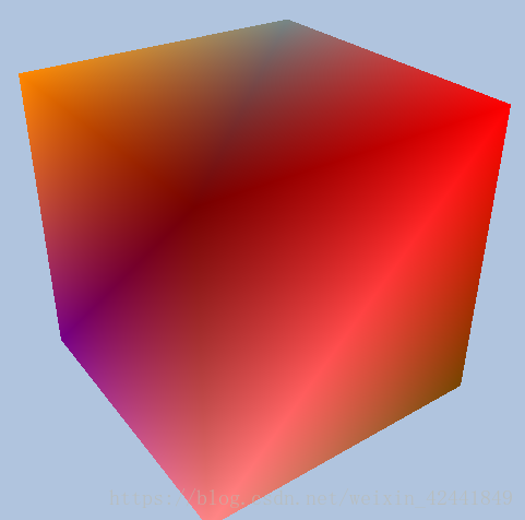
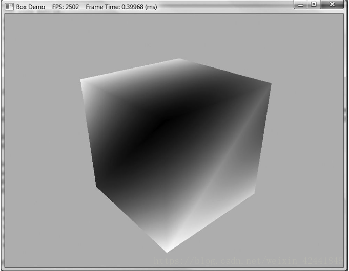
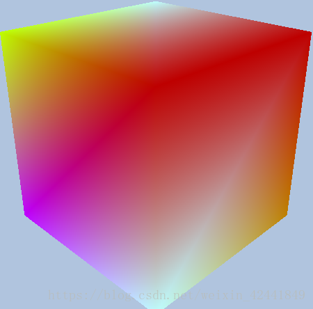
11 Box Demo
代码工程地址:(或者带本书官方网站下载示例工程)
https://githu.com/jiabaodan/Direct12BookReadingNotes
12 本章总结
- 在Direct3D中,顶点除了位置以外还可以包含其他数据,为了定义一个自定义的顶点,我们可以定义一个顶点结构来选择我们需要的数据;顶点结构定义完成后,我们使用输入布局描述(D3D12_INPUT_LAYOUT_DESC)来向Direct3D描述定义的顶点;它是PSO中的一个结构D3D12_GRAPHICS_PIPELINE_STATE_DESC,并且它针对定点着色器输入签名来验证兼容性。一个输入布局是在PSO被绑定是,绑定到IA阶段。
- 为了让GPU访问到顶点/索引数组,它们需要放在缓冲中(ID3D12Resource接口);一个缓冲是通过赋值D3D12_RESOURCE_DESC结构体,并调用ID3D12Device::CreateCommittedResource来创建。顶点缓冲的描述用D3D12_VERTEX_BUFFER_VIEW结构来定义,索引缓冲的描述是使用D3D12_INDEX_BUFFER_VIEW结构;顶点缓冲使用ID3D12GraphicsCommandList::IASetVertexBuffers方法来绑定到IA阶段;索引缓冲使用ID3D12GraphicsCommandList::IASetIndexBuffer方法;无索引几何体可以使用ID3D12GraphicsCommandList::DrawInstanced方法来绘制,有索引的几何体使用ID3D12GraphicsCommandList::DrawIndexedInstanced;
- 顶点着色器是用HLSL编写,运行在GPU上的代码;它输入一个顶点数据,输出一个顶点数据。每一个需要绘制的顶点都需要通过顶点着色器执行;这可以让程序员基于顶点设计和制作很多特殊的效果。输出的顶点将会输出到渲染流水线下一阶段;
- 一个常量缓冲是着色器程序可以访问到的GPU资源(ID3D12Resource),它创建在上传堆中(upload heap)而不是默认堆,所以应用可以直接通过拷贝系统内存到GPU内存来更新它的数据。通过这种方法,C++程序就可以和着色器程序更新数据;
- 一个像素着色器是使用HLSL编写的执行在GPU上的代码,它输入一个顶点数据,输出一个颜色。硬件在优化时,会尽可能在执行像素着色器之前排除不需要的像素。像素着色器可以让程序员基于像素达到很多效果;
- 大部分渲染控制状态都放在PSO对象的集合中,这样做是为了优化性能;放到一起,Direct3D可以验证所有状态的兼容性,驱动可以一次生成所有代码。
13 练习题
- 为下列顶点结构写出D3D12_INPUT_ELEMENT_DESC数组:
		struct Vertex
		{
			XMFLOAT3 Pos;
			XMFLOAT3 Tangent;
			XMFLOAT3 Normal;
			XMFLOAT2 Tex0;
			XMFLOAT2 Tex1;
			XMCOLOR Color;
		};
答:
D3D12_INPUT_ELEMENT_DESC desc[] =
{
	{"POSITION", 0, DXGI_FORMAT_R32G32B32_FLOAT, 0, 0, D3D12_INPUT_PER_VERTEX_DATA, 0},
	{"TANGENT", 0, DXGI_FORMAT_R32G32B32_FLOAT, 0, 12, D3D12_INPUT_PER_VERTEX_DATA, 0},
	{"NORMAL", 0, DXGI_FORMAT_R32G32B32_FLOAT, 0, 24, D3D12_INPUT_PER_VERTEX_DATA, 0},
	{"TEXCOORD", 0, DXGI_FORMAT_R32G32_FLOAT, 0, 32, D3D12_INPUT_PER_VERTEX_DATA, 0},
	{"TEXCOORD", 1, DXGI_FORMAT_R32G32_FLOAT, 0, 40, D3D12_INPUT_PER_VERTEX_DATA, 0},
	{"COLOR", 0, DXGI_FORMAT_R32G32B32A32_FLOAT , 0, 48, D3D12_INPUT_PER_VERTEX_DATA, 0}
};
- 重做方块的示例,但是这次使用2个顶点缓冲,一个保存位置,一个保存颜色。所以你需要2个顶点结构:
struct VPosData
{
	XMFLOAT3 Pos;
};
struct VColorData
{
	XMFLOAT4 Color;
};
你的D3D12_INPUT_ELEMENT_DESC数组看起来会是下面这样:
D3D12_INPUT_ELEMENT_DESC vertexDesc[] =
{
	{"POSITION", 0, DXGI_FORMAT_R32G32B32_FLOAT, 0, 0, D3D12_INPUT_PER_VERTEX_DATA, 0},
	{"COLOR", 0, DXGI_FORMAT_R32G32B32A32_FLOAT, 1, 0, D3D12_INPUT_PER_VERTEX_DATA, 0}
};
位置数据和输入槽0挂钩,颜色数据和输入槽1挂钩;另外D3D12_INPUT_ELEMENT_DESC::AlignedByteOffset都是0,因为它们不在同一个输入槽中交叉。然后使用ID3D12CommandList::IASetVertexBuffers将它们分别绑定在输入槽0和1中。这种方式可以用以优化,比如在阴影贴图算法中,每帧我们需要绘制我们的场景2次:一次从光源(shadow pass),一次从主摄像机(main pass);Shadow pass只需要位置和纹理坐标(用以alpha测试);所以我们可以把顶点数据划分为2个输入槽,一个包含位置和纹理坐标,其他属性放到另一个输入槽中。这样就为shadow pass节省了数据带宽。出于性能考虑,建议输入槽数量要少于等于3。
答:创建一个派生于MeshGeometry的类,包含2个顶点缓冲相关的对象和数据,然后根据提示创建2个对应数据
代码在 https://github.com/jiabaodan/Direct12BookReadingNotes 中的 Chapter6_Exercises_2 工程
-
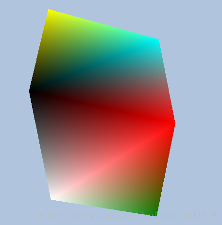
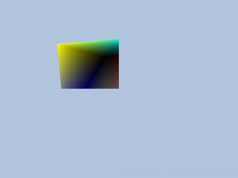
绘制类似5.13a,b,c,d和5.14a的图像:
答:调整顶点的拓扑类型即可mCommandList->IASetPrimitiveTopology
代码在 https://github.com/jiabaodan/Direct12BookReadingNotes 中的 Chapter6_Exercises_3 工程 -
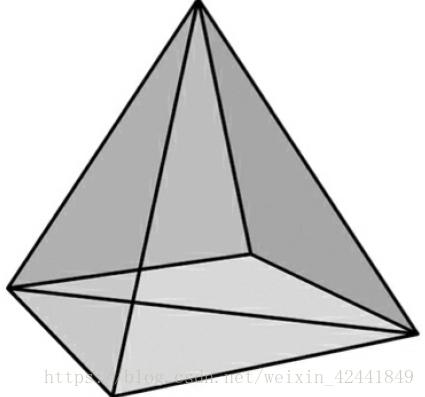
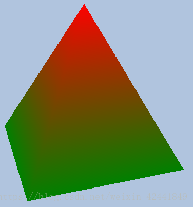
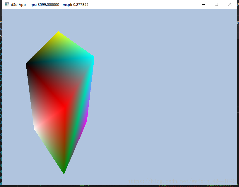
绘制下面的金字塔,底部是绿色,顶部是红色:
答:重置下顶点和索引即可:
代码在 https://github.com/jiabaodan/Direct12BookReadingNotes 中的 Chapter6_Exercises_4 工程 -
运行盒子示例,解释为啥我们只指明了顶点位置和颜色,但是在像素着色器中可以为每个像素计算颜色
答:因为根据顶点的位置和颜色,在三角形内会做差值运算。 -
在盒子示例中,在顶点着色器中变换到世界坐标系之前,为每个顶点执行下面的变换代码:
vin.PosL.xy += 0.5f*sin(vinL.Pos.x)*sin(3.0f*gTime);
vin.PosL.z *= 0.6f + 0.4f*sin(2.0f*gTime);
你需要在常量缓冲中添加gTime参数,它对应于GameTimer::TotalTime()的值,它会让顶点周期性的根据sin函数产生变形动画。
答:常量缓冲中添加参数并在Update中更新即可,然后修改Shader
代码在 https://github.com/jiabaodan/Direct12BookReadingNotes 中的 Chapter6_Exercises_6 工程
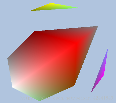
- 将盒子示例和金字塔(练习4中的)的顶点合并到一个大的顶点缓冲中,同时合并索引,但是不修改索引的值,然后通过ID3D12CommandList::DrawIndexedInstanced方法一个一个绘制它们;使用世界变换矩阵让它们不相交。
答:根据StartIndexLocation、BaseVertexLocation和IndexCount来区分2个形状;然后创建2个CB,CBV,和CBV堆来设置不同的位置。
代码在 https://github.com/jiabaodan/Direct12BookReadingNotes 中的 Chapter6_Exercises_7 工程
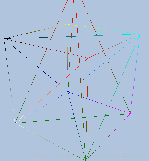
- 修改为线框显示模式:
答:修改PSO中RasterizerState值即可:
CD3DX12_RASTERIZER_DESC rsDesc = CD3DX12_RASTERIZER_DESC(D3D12_DEFAULT);
	rsDesc.FillMode = D3D12_FILL_MODE_WIREFRAME;
	rsDesc.CullMode = D3D12_CULL_MODE_NONE;

	psoDesc.RasterizerState = rsDesc;
-
开启和关闭背面消除测试:
答:修改PSO中RasterizerState值即可,同第八题。 -
如果顶点内存很重要,那么128位的颜色减少到32位就很值得。将盒子示例中使用32位颜色,你的顶点结构应该如下:
struct Vertex
{
	XMFLOAT3 Pos;
	XMCOLOR Color;
};

D3D12_INPUT_ELEMENT_DESC vertexDesc[] =
{
	{"POSITION", 0, DXGI_FORMAT_R32G32B32_FLOAT, 0, 0, D3D12_INPUT_PER_VERTEX_DATA, 0},
	{"COLOR", 0, DXGI_FORMAT_B8G8R8A8_UNORM, 0, 12, D3D12_INPUT_PER_VERTEX_DATA, 0}
};
我们使用DXGI_FORMAT_B8G8R8A8_UNORM格式,它对应于32位图形颜色ARGB,但是DXGI_FORMAT标识在内存中是低位优先的;该模式中,多字节数据中的字节是从最不重要的到最重要的来保存;所以ARGB在内存中格式以BGRA形式来保存。
答:修改后有报错,后续章节中解决(提示XMCOLOR未定义)。
- 考虑下面的顶点结构:
struct Vertex
{
	XMFLOAT3 Pos;
	XMFLOAT4 Color;
};
a、下面的顶点输入描述兼容上面的顶点结构吗?实验验证结果
D3D11_INPUT_ELEMENT_DESC vertexDesc[] =
{
	{"COLOR", 0, DXGI_FORMAT_R32G32B32A32_FLOAT, 0, 12, D3D11_INPUT_PER_VERTEX_DATA, 0},
	{"POSITION", 0, DXGI_FORMAT_R32G32B32_FLOAT, 0, 0, D3D11_INPUT_PER_VERTEX_DATA, 0},
};
答:是兼容的,因为偏移量是正确的。
b、下面的Shader结构兼容上面的顶点结构吗?实验证明结果:
struct VertexIn
{
	float4 Color : COLOR;
	float3 Pos : POSITION;
};
答:是兼容的,因为后面的标识(COLOR POSITION)是对应的。
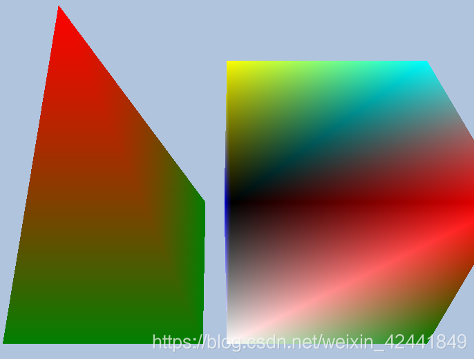
- 在后置缓冲中把视口设置成左半边:
答:将视口配置宽度设成一般即可:
mScreenViewport.Width = static_cast<float>(mClientWidth / 2);
代码在 https://github.com/jiabaodan/Direct12BookReadingNotes 中的 Chapter6_Exercises_12_HalfViewport 工程
- 使用裁切测试将mClientWidth/2和mClientHeight/2矩形框以外的像素都裁切掉,记得在PSO中还要启用裁切测试:
答:重置裁切测试尺寸即可:
	// 重置裁切测试尺寸
	mScissorRect = { 0, 0, mClientWidth / 2, mClientHeight / 2 };
代码在 https://github.com/jiabaodan/Direct12BookReadingNotes 中的 Chapter6_Exercises_13_ScissorTest 工程
- 像素着色器色彩化,使用常量缓冲让颜色根据时间产生动画;使用smooth easing函数,在像素和顶点着色器中使用:
答:在常量缓冲中添加时间参数,然后像素着色器修改如下(顶点着色器类似):
cbuffer cbPerObject : register(b0)
{
	float4x4 gWorldViewProj;
	float gTime;
};

float4 PS(VertexOut pin) : SV_Target
{
	float4 c = pin.Color;
	c.x = smoothstep(-1, 1, sin(gTime));

    return c;
}
代码在 https://github.com/jiabaodan/Direct12BookReadingNotes 中的 Chapter6_Exercises_14_ColorTint 工程
- 修改盒子示例中的像素着色器:
float4 PS(VertexOut pin) : SV_Target
{
	clip(pin.Color.r - 0.5f);
	return pin.Color;
}
答:Clip函数中参数如果小于0,则放弃当前像素
代码在 https://github.com/jiabaodan/Direct12BookReadingNotes 中的 Chapter6_Exercises_15_ColorClip 工程
- 修改盒子示例中的像素着色器,让颜色在设定的gPulseColor和顶点颜色之间平滑跳动;你需要更新常量缓冲,然后修改像素着色器如下:
cbuffer cbPerObject : register(b0)
{
	float4x4 gWorldViewProj;
	float4 gPulseColor;
	float gTime;
};

float4 PS(VertexOut pin) : SV_Target
{
	const float pi = 3.14159;

	// Oscillate a value in [0,1] over time using a sine function.
	float s = 0.5f*sin(2*gTime - 0.25f*pi)+0.5f;

	// Linearly interpolate between pin.Color and gPulseColor based on
	// parameter s.
	float4 c = lerp(pin.Color, gPulseColor, s);

	return c;
}
gTime参数对应于GameTimer::TotalTime()的值。
答:代码在 https://github.com/jiabaodan/Direct12BookReadingNotes 中的 Chapter6_Exercises_16_ColorPulse 工程