代码工程地址:
https://github.com/jiabaodan/Direct12BookReadingNotes
学习目标
- 理解本章中针对命令队列的更新(不再需要每帧都flush命令队列),提高性能;
- 理解其他两种类型的根信号参数类型:根描述和根常量;
- 熟悉如何通过程序方法来绘制通用的几何形状:盒子,圆柱体和球体;
- 学习如何在CPU做顶点动画,并且通过动态顶点缓冲将顶点数据上传到GPU内存。
1 帧资源
在之前的代码中,我们在每帧结束的时候调用D3DApp::FlushCommandQueue方法来同步CPU和GPU,这个方法可以使用,但是很低效:
- 在每帧开始的时候,GPU没有任何命令可以执行,所以它一直在等待,直到CPU提交命令;
- 每帧的结尾,CPU需要等待GPU执行完命令。
这个问题的其中一个解决方案是针对CPU更新的资源创建一个环形数组,我们叫它帧资源(frame resources),通常情况下数组中使用3个元素。该方案中,CPU提交资源后,将会获取下一个可使用的资源(GPU没有在执行的)继续数据的更新,使用3个元素可以确保CPU提前2个元素更新,这样就可以保证GPU一直的高效运算。下面的例子是使用在Shape示例中的,因为CPU只需要更新常量缓冲,所以帧数据只包含常量缓冲:
// Stores the resources needed for the CPU to build the command lists
// for a frame. The contents here will vary from app to app based on
// the needed resources.
struct FrameResource
{
public:
	FrameResource(ID3D12Device* device, UINT passCount, UINT objectCount);
	FrameResource(const FrameResource& rhs) = delete;
	FrameResource& operator=(const FrameResource& rhs) = delete;
	˜FrameResource();

	// We cannot reset the allocator until the GPU is done processing the
	// commands. So each frame needs their own allocator.
	Microsoft::WRL::ComPtr<ID3D12CommandAllocator> CmdListAlloc;

	// We cannot update a cbuffer until the GPU is done processing the
	// commands that reference it. So each frame needs their own cbuffers.
	std::unique_ptr<UploadBuffer<PassConstants>> PassCB = nullptr;
	std::unique_ptr<UploadBuffer<ObjectConstants>> ObjectCB = nullptr;

	// Fence value to mark commands up to this fence point. This lets us
	// check if these frame resources are still in use by the GPU.
	UINT64 Fence = 0;
};

FrameResource::FrameResource(ID3D12Device* device, UINT passCount, UINT objectCount)
{
	ThrowIfFailed(device->CreateCommandAllocator(
		D3D12_COMMAND_LIST_TYPE_DIRECT,
		IID_PPV_ARGS(CmdListAlloc.GetAddressOf())));

	PassCB = std::make_unique<UploadBuffer<PassConstants>> (device, passCount, true);
	ObjectCB = std::make_unique<UploadBuffer<ObjectConstants>> (device, objectCount, true);
}

FrameResource::˜ FrameResource()
{
}
在我们的应用中使用Vector来实例化3个资源,并且跟踪当前的资源:
static const int NumFrameResources = 3;
std::vector<std::unique_ptr<FrameResource>> mFrameResources;
FrameResource* mCurrFrameResource = nullptr;
int mCurrFrameResourceIndex = 0;
void ShapesApp::BuildFrameResources()
{
	for(int i = 0; i < gNumFrameResources; ++i)
	{
		mFrameResources.push_back(std::make_unique<FrameResource> (
			md3dDevice.Get(), 1,
			(UINT)mAllRitems.size()));
	}
}
现在对于CPU第N帧,执行算法是:
void ShapesApp::Update(const GameTimer& gt)
{
	// Cycle through the circular frame resource array.
	mCurrFrameResourceIndex = (mCurrFrameResourceIndex + 1) % NumFrameResources;
	mCurrFrameResource = mFrameResources[mCurrFrameResourceIndex];

	// Has the GPU finished processing the commands of the current frame
	// resource. If not, wait until the GPU has completed commands up to
	// this fence point.
	if(mCurrFrameResource->Fence != 0
		&& mCommandQueue->GetLastCompletedFence() < mCurrFrameResource->Fence)
	{
		HANDLE eventHandle = CreateEventEx(nullptr, false, false, EVENT_ALL_ACCESS);

		ThrowIfFailed(mCommandQueue->SetEventOnFenceCompletion(
			mCurrFrameResource->Fence, eventHandle));

		WaitForSingleObject(eventHandle, INFINITE);
		CloseHandle(eventHandle);
	}

	// […] Update resources in mCurrFrameResource (like cbuffers).
}

void ShapesApp::Draw(const GameTimer& gt)
{
	// […] Build and submit command lists for this frame.
	// Advance the fence value to mark commands up to this fence point.
	mCurrFrameResource->Fence = ++mCurrentFence;

	// Add an instruction to the command queue to set a new fence point.
	// Because we are on the GPU timeline, the new fence point won’t be
	// set until the GPU finishes processing all the commands prior to
	// this Signal().
	mCommandQueue->Signal(mFence.Get(), mCurrentFence);

	// Note that GPU could still be working on commands from previous
	// frames, but that is okay, because we are not touching any frame
	// resources associated with those frames.
}
这个方案并没有完美解决等待,如果其中一个处理器处理太快,它还是要等待另一个处理器。
2 渲染物体(RENDER ITEMS)
绘制一个物体需要设置大量参数,比如创建顶点和索引缓存,绑定常量缓冲,设置拓扑结构,指定DrawIndexedInstanced参数。如果我们要绘制多个物体,设计和创建一个轻量级结构用来保存上述所有数据就很有用。我们对这一组单个绘制调用需要的所有数据称之为一个渲染物体(render item),当前Demo中,我们RenderItem结构如下:
// Lightweight structure stores parameters to draw a shape. This will
// vary from app-to-app.
struct RenderItem
{
	RenderItem() = default;

	// World matrix of the shape that describes the object’s local space
	// relative to the world space, which defines the position,
	// orientation, and scale of the object in the world.
	XMFLOAT4X4 World = MathHelper::Identity4x4();

	// Dirty flag indicating the object data has changed and we need
	// to update the constant buffer. Because we have an object
	// cbuffer for each FrameResource, we have to apply the
	// update to each FrameResource. Thus, when we modify obect data we
	// should set
	// NumFramesDirty = gNumFrameResources so that each frame resource
	// gets the update.
	int NumFramesDirty = gNumFrameResources;

	// Index into GPU constant buffer corresponding to the ObjectCB
	// for this render item.
	UINT ObjCBIndex = -1;

	// Geometry associated with this render-item. Note that multiple
	// render-items can share the same geometry.
	MeshGeometry* Geo = nullptr;

	// Primitive topology.
	D3D12_PRIMITIVE_TOPOLOGY PrimitiveType = D3D_PRIMITIVE_TOPOLOGY_TRIANGLELIST;

	// DrawIndexedInstanced parameters.
	UINT IndexCount = 0;
	UINT StartIndexLocation = 0;
	int BaseVertexLocation = 0;
};
我们的应用将包含一个渲染物体列表来表示他们如何渲染;需要不同PSO的物体会放置到不同的列表中:
// List of all the render items.
std::vector<std::unique_ptr<RenderItem>> mAllRitems;

// Render items divided by PSO.
std::vector<RenderItem*> mOpaqueRitems;
std::vector<RenderItem*> mTransparentRitems;
3 PASS CONSTANTS
之前的章节中我们介绍了一个新的常量缓冲:
std::unique_ptr<UploadBuffer<PassConstants>> PassCB = nullptr;
它主要包含一些各个物体通用的常量,比如眼睛位置,透视投影矩阵,屏幕分辨率数据,还包括时间数据等。目前我们的Demo不需要所有这些数据,但是都实现他们会很方便,并且只会消耗很少的额外数据空间。比如我们如果要做一些后期特效,渲染目标尺寸数据就很有用:
cbuffer cbPass : register(b1)
{
	float4x4 gView;
	float4x4 gInvView;
	float4x4 gProj;
	float4x4 gInvProj;
	float4x4 gViewProj;
	float4x4 gInvViewProj;
	float3 gEyePosW;
	float cbPerObjectPad1;
	float2 gRenderTargetSize;
	float2 gInvRenderTargetSize;
	float gNearZ;
	float gFarZ;
	float gTotalTime;
	float gDeltaTime;
};
我们也需要修改之和每个物体关联的常量缓冲。目前我们只需要世界变换矩阵:
cbuffer cbPerObject : register(b0)
{
	float4x4 gWorld;
};
这样做的好处是可以将常量缓冲分组进行更新,每一个pass更新的常量缓冲需要每一个渲染Pass的时候更新;物体常量只需要当物体世界矩阵变换的时候更新;静态物体只需要在初始化的时候更新一下。在我们Demo中,实现了下面的方法来更新常量缓冲,它们每帧在Update中调用一次:
void ShapesApp::UpdateObjectCBs(const GameTimer& gt)
{
	auto currObjectCB = mCurrFrameResource->ObjectCB.get();

	for(auto& e : mAllRitems)
	{
		// Only update the cbuffer data if the constants have changed.
		// This needs to be tracked per frame resource.
		if(e->NumFramesDirty > 0)
		{
			XMMATRIX world = XMLoadFloat4x4(&e->World);
			ObjectConstants objConstants;
			XMStoreFloat4x4(&objConstants.World, XMMatrixTranspose(world));
			currObjectCB->CopyData(e->ObjCBIndex, objConstants);

			// Next FrameResource need to be updated too.
			e->NumFramesDirty--;
		}
	}
}

void ShapesApp::UpdateMainPassCB(const GameTimer& gt)
{
	XMMATRIX view = XMLoadFloat4x4(&mView);
	XMMATRIX proj = XMLoadFloat4x4(&mProj);
	XMMATRIX viewProj = XMMatrixMultiply(view, proj);
	XMMATRIX invView = XMMatrixInverse(&XMMatrixDeterminant(view), view);
	XMMATRIX invProj = XMMatrixInverse(&XMMatrixDeterminant(proj), proj);
	XMMATRIX invViewProj = 	XMMatrixInverse(&XMMatrixDeterminant(viewProj), viewProj);
	XMStoreFloat4x4(&mMainPassCB.View, XMMatrixTranspose(view));
	XMStoreFloat4x4(&mMainPassCB.InvView, XMMatrixTranspose(invView));
	XMStoreFloat4x4(&mMainPassCB.Proj, XMMatrixTranspose(proj));
	XMStoreFloat4x4(&mMainPassCB.InvProj, XMMatrixTranspose(invProj));
	XMStoreFloat4x4(&mMainPassCB.ViewProj, XMMatrixTranspose(viewProj));
	XMStoreFloat4x4(&mMainPassCB.InvViewProj, XMMatrixTranspose(invViewProj));
	mMainPassCB.EyePosW = mEyePos;
	mMainPassCB.RenderTargetSize = XMFLOAT2((float)mClientWidth, (float)mClientHeight);
	mMainPassCB.InvRenderTargetSize = XMFLOAT2(1.0f / mClientWidth, 1.0f / mClientHeight);
	mMainPassCB.NearZ = 1.0f;
	mMainPassCB.FarZ = 1000.0f;
	mMainPassCB.TotalTime = gt.TotalTime();
	mMainPassCB.DeltaTime = gt.DeltaTime();
	auto currPassCB = mCurrFrameResource->PassCB.get();
	currPassCB->CopyData(0, mMainPassCB);
}
我们更新顶点着色器相应的支持这个缓冲变换:
VertexOut VS(VertexIn vin)
{
	VertexOut vout;

	// Transform to homogeneous clip space.
	float4 posW = mul(float4(vin.PosL, 1.0f), gWorld);
	vout.PosH = mul(posW, gViewProj);

	// Just pass vertex color into the pixel shader.
	vout.Color = vin.Color;

	return vout;
}
这里额外的逐顶点矩阵相乘,在现在强大的GPU上是微不足道的。
着色器需要的资源发生变化,所以需要更新根签名相应的包含两个描述表:
CD3DX12_DESCRIPTOR_RANGE cbvTable0;
cbvTable0.Init(D3D12_DESCRIPTOR_RANGE_TYPE_CBV, 1, 0);

CD3DX12_DESCRIPTOR_RANGE cbvTable1;
cbvTable1.Init(D3D12_DESCRIPTOR_RANGE_TYPE_CBV, 1, 1);

// Root parameter can be a table, root descriptor or root constants.
CD3DX12_ROOT_PARAMETER slotRootParameter[2];

// Create root CBVs.
slotRootParameter[0].InitAsDescriptorTable(1, &cbvTable0);
slotRootParameter[1].InitAsDescriptorTable(1, &cbvTable1);

// A root signature is an array of root parameters.
CD3DX12_ROOT_SIGNATURE_DESC rootSigDesc(2,
	slotRootParameter, 0, nullptr,
	D3D12_ROOT_SIGNATURE_FLAG_ALLOW_INPUT_ASSEMBLER_INPUT__LAYOUT);
不要在着色器中使用太多的常量缓冲,为了性能[Thibieroz13]建议保持在5个以下。
4 形状几何
这节将会展示如何创建椭球体,球体,圆柱体和圆锥体。这些形状对于绘制天空示例,Debugging,可视化碰撞检测和延时渲染非常有用。
我们将在程序中创建几何体的代码放在GeometryGenerator(GeometryGenerator.h/.cpp)类中,该类创建的数据保存在内存中,所以我们还需要将它们赋值到顶点/索引缓冲中。MeshData结构是一个内嵌在GeometryGenerator中用来保存顶点和索引列表的简单结构:
class GeometryGenerator
{
public:
	using uint16 = std::uint16_t;
	using uint32 = std::uint32_t;

	struct Vertex
	{
		Vertex(){}
		Vertex(
			const DirectX::XMFLOAT3& p,
			const DirectX::XMFLOAT3& n,
			const DirectX::XMFLOAT3& t,
			const DirectX::XMFLOAT2& uv) :
			Position(p),
			Normal(n),
			TangentU(t),
			TexC(uv){}

		Vertex(
			float px, float py, float pz,
			float nx, float ny, float nz,
			float tx, float ty, float tz,
			float u, float v) :
			Position(px,py,pz),
			Normal(nx,ny,nz),
			TangentU(tx, ty, tz),
			TexC(u,v){}

		DirectX::XMFLOAT3 Position;
		DirectX::XMFLOAT3 Normal;
		DirectX::XMFLOAT3 TangentU;
		DirectX::XMFLOAT2 TexC;
	};

	struct MeshData
	{
		std::vector<Vertex> Vertices;
		std::vector<uint32> Indices32;
		std::vector<uint16>& GetIndices16()
		{
			if(mIndices16.empty())
			{
				mIndices16.resize(Indices32.size());
				for(size_t i = 0; i < Indices32.size(); ++i)
					mIndices16[i] = static_cast<uint16> (Indices32[i]);
			}
			return mIndices16;
		}

	private:
		std::vector<uint16> mIndices16;
	};
	…
};
4.1 创建圆柱体网格
我们通过定义底面和顶面半径,高度,切片(slice)和堆叠(stack)个数来定义一个圆柱体网格,如下图,我们将圆柱体划分成侧面,底面和顶面:
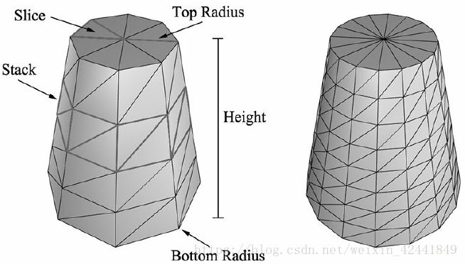
4.1.1 圆柱体侧面几何
我们创建的圆柱体中心的原点,平行于Y轴,所有顶点依赖于环(rings)。每个圆柱体有stackCount + 1环,每一环有sliceCount个独立的顶点。每一环半径的变化为(topRadius – bottomRadius)/stackCount;所以基本的创建圆柱体的思路就是遍历每一环创建顶点:
GeometryGenerator::MeshData
GeometryGenerator::CreateCylinder(
	float bottomRadius, float topRadius,
	float height, uint32 sliceCount, uint32
	stackCount)
{
	MeshData meshData;

	//
	// Build Stacks.
	//
	float stackHeight = height / stackCount;

	// Amount to increment radius as we move up each stack level from
	// bottom to top.
	float radiusStep = (topRadius - bottomRadius) / stackCount;
	uint32 ringCount = stackCount+1;

	// Compute vertices for each stack ring starting at the bottom and
	// moving up.
	for(uint32 i = 0; i < ringCount; ++i)
	{
		float y = -0.5f*height + i*stackHeight;
		float r = bottomRadius + i*radiusStep;

		// vertices of ring
		float dTheta = 2.0f*XM_PI/sliceCount;
		for(uint32 j = 0; j <= sliceCount; ++j)
		{
			Vertex vertex;
			float c = cosf(j*dTheta);
			float s = sinf(j*dTheta);
			vertex.Position = XMFLOAT3(r*c, y, r*s);
			vertex.TexC.x = (float)j/sliceCount;
			vertex.TexC.y = 1.0f - (float)i/stackCount;

			// Cylinder can be parameterized as follows, where we introduce v
			// parameter that goes in the same direction as the v tex-coord
			// so that the bitangent goes in the same direction as the
			// v tex-coord.
			// Let r0 be the bottom radius and let r1 be the top radius.
			// y(v) = h - hv for v in [0,1].
			// r(v) = r1 + (r0-r1)v
			//
			// x(t, v) = r(v)*cos(t)
			// y(t, v) = h - hv
			// z(t, v) = r(v)*sin(t)
			//
			// dx/dt = -r(v)*sin(t)
			// dy/dt = 0
			// dz/dt = +r(v)*cos(t)
			//
			// dx/dv = (r0-r1)*cos(t)
			// dy/dv = -h
			// dz/dv = (r0-r1)*sin(t)
			// This is unit length.
			vertex.TangentU = XMFLOAT3(-s, 0.0f, c);
			float dr = bottomRadius-topRadius;
			XMFLOAT3 bitangent(dr*c, -height, dr*s);
			XMVECTOR T = XMLoadFloat3(&vertex.TangentU);
			XMVECTOR B = XMLoadFloat3(&bitangent);
			XMVECTOR N = XMVector3Normalize(XMVector3Cross(T, B));
			XMStoreFloat3(&vertex.Normal, N);
			meshData.Vertices.push_back(vertex);
		}
	}
}
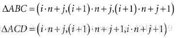
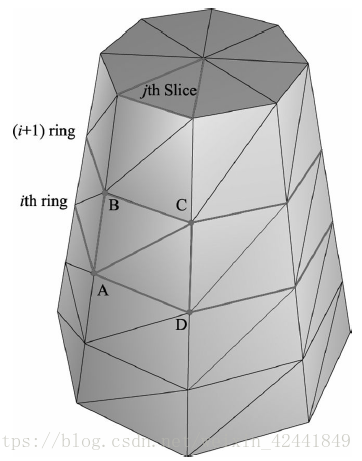
侧面的每个四边形中有2个三角形,所以第i层的第j个切片的索引计算如下:
n是每环中顶点的索引,所以创建索引的思路是遍历每一层的每一个切面,然后应用上面的公式:
	// Add one because we duplicate the first and last vertex per ring
	// since the texture coordinates are different.
	uint32 ringVertexCount = sliceCount+1;

	// Compute indices for each stack.
	for(uint32 i = 0; i < stackCount; ++i)
	{
		for(uint32 j = 0; j < sliceCount; ++j)
		{
			meshData.Indices32.push_back(i*ringVertexCount + j);
			meshData.Indices32.push_back((i+1)*ringVertexCount + j);
			meshData.Indices32.push_back((i+1)*ringVertexCount + j+1);
			meshData.Indices32.push_back(i*ringVertexCount + j);
			meshData.Indices32.push_back((i+1)*ringVertexCount + j+1);
			meshData.Indices32.push_back(i*ringVertexCount + j+1);
			}
	}

	BuildCylinderTopCap(bottomRadius, topRadius, height, sliceCount, stackCount, meshData);
	BuildCylinderBottomCap(bottomRadius, topRadius, height, sliceCount, stackCount, meshData);

	return meshData;
}
4.1.2 上下盖
对顶面和底面通过创建切面数量个三角形模拟出近似的圆:
void GeometryGenerator::BuildCylinderTopCap(
	float bottomRadius, float topRadius, float height,
	uint32 sliceCount, uint32 stackCount, MeshData& meshData)
{
	uint32 baseIndex = (uint32)meshData.Vertices.size();
	float y = 0.5f*height;
	float dTheta = 2.0f*XM_PI/sliceCount;

	// Duplicate cap ring vertices because the texture coordinates and
	// normals differ.
	for(uint32 i = 0; i <= sliceCount; ++i)
	{
		float x = topRadius*cosf(i*dTheta);
		float z = topRadius*sinf(i*dTheta);

		// Scale down by the height to try and make top cap texture coord
		// area proportional to base.
		float u = x/height + 0.5f;
		float v = z/height + 0.5f;
		meshData.Vertices.push_back(Vertex(x, y, z, 0.0f, 1.0f, 0.0f, 1.0f, 0.0f, 0.0f, u, v) );
	}

	// Cap center vertex.
	meshData.Vertices.push_back( Vertex(0.0f, y, 0.0f, 0.0f, 1.0f, 0.0f, 1.0f, 0.0f, 0.0f, 0.5f, 0.5f) );

	// Index of center vertex.
	uint32 centerIndex = (uint32)meshData.Vertices.size()-1;
	for(uint32 i = 0; i < sliceCount; ++i)
	{
		meshData.Indices32.push_back(centerIndex);
		meshData.Indices32.push_back(baseIndex + i+1);
		meshData.Indices32.push_back(baseIndex + i);
	}
}
底部代码类似
4.2 创建球体网格
我们通过定义半径,切面和堆叠数来定义一个球体。创建球体的算法和圆柱体的算法非常类似,除了每环半径的变化是非线性的基于三角函数的方程(GeometryGenerator::CreateSphere代码中)。我们可以通过缩放球体来创建椭圆形。
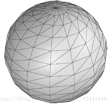
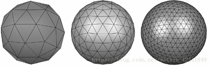
4.3 创建三角面片球体(Geosphere)网格
上节创建的球体并不具有相同的面积,在某些需求下这是不合需求的。一个三角面片球体使用相同面积和边长的三角形组成近似的球体。
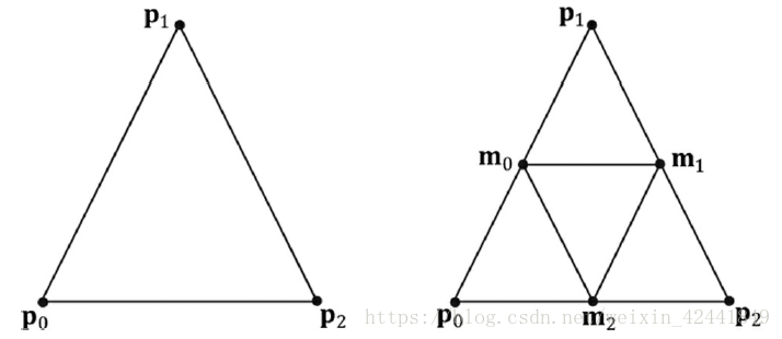
为了创建它,我们从一个二十面体开始,细分每个三角形然后将顶点映射到给定半径的一个球体上。我们重复这个过程来对三角形细分。
下图展示了如何细分三角形,就是简单的找到每个边的中点。
GeometryGenerator::MeshData GeometryGenerator::CreateGeosphere(float radius, uint32 numSubdivisions)
{
	MeshData meshData;
	// Put a cap on the number of subdivisions.
	numSubdivisions = std::min<uint32> (numSubdivisions, 6u);

	// Approximate a sphere by tessellating an icosahedron.
	const float X = 0.525731f;
	const float Z = 0.850651f;
	XMFLOAT3 pos[12] =
	{
		XMFLOAT3(-X, 0.0f, Z), XMFLOAT3(X, 0.0f, Z),
		XMFLOAT3(-X, 0.0f, -Z), XMFLOAT3(X, 0.0f, - Z),
		XMFLOAT3(0.0f, Z, X), XMFLOAT3(0.0f, Z, - X),
		XMFLOAT3(0.0f, -Z, X), XMFLOAT3(0.0f, -Z, - X),
		XMFLOAT3(Z, X, 0.0f), XMFLOAT3(-Z, X, 0.0f),
		XMFLOAT3(Z, -X, 0.0f), XMFLOAT3(-Z, -X, 0.0f)
	};
	uint32 k[60] =
	{
		1,4,0, 4,9,0, 4,5,9, 8,5,4, 1,8,4,
		1,10,8, 10,3,8, 8,3,5, 3,2,5, 3,7,2,
		3,10,7, 10,6,7, 6,11,7, 6,0,11, 6,1,0,
		10,1,6, 11,0,9, 2,11,9, 5,2,9, 11,2,7
	};
	meshData.Vertices.resize(12);
	meshData.Indices32.assign(&k[0], &k[60]);

	for(uint32 i = 0; i < 12; ++i)
		meshData.Vertices[i].Position = pos[i];

	for(uint32 i = 0; i < numSubdivisions; ++i)
		Subdivide(meshData);

	// Project vertices onto sphere and scale.
	for(uint32 i = 0; i < meshData.Vertices.size(); ++i)
	{
		// Project onto unit sphere.
		XMVECTOR n = XMVector3Normalize(XMLoadFloat3(&meshData.Vertices[i].Position));

		// Project onto sphere.
		XMVECTOR p = radius*n;
		XMStoreFloat3(&meshData.Vertices[i].Position, p);
		XMStoreFloat3(&meshData.Vertices[i].Normal, n);

		// Derive texture coordinates from spherical coordinates.
		float theta = atan2f(meshData.Vertices[i].Position.z, meshData.Vertices[i].Position.x);

		// Put in [0, 2pi].
		if(theta < 0.0f)
			theta += XM_2PI;

		float phi = acosf(meshData.Vertices[i].Position.y / radius);
		meshData.Vertices[i].TexC.x = theta/XM_2PI;
		meshData.Vertices[i].TexC.y = phi/XM_PI;

		// Partial derivative of P with respect to theta
		meshData.Vertices[i].TangentU.x = -radius*sinf(phi)*sinf(theta);
		meshData.Vertices[i].TangentU.y = 0.0f;
		meshData.Vertices[i].TangentU.z = +radius*sinf(phi)*cosf(theta);
		XMVECTOR T = XMLoadFloat3(&meshData.Vertices[i].TangentU);
		XMStoreFloat3(&meshData.Vertices[i].TangentU, XMVector3Normalize(T));
	}

	return meshData;
}
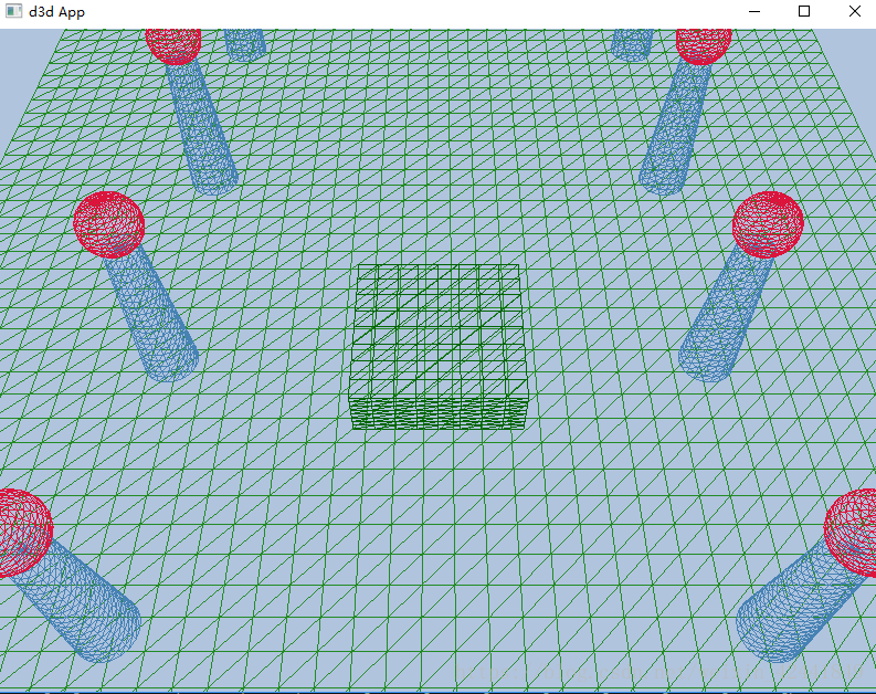
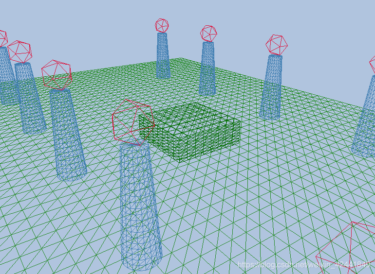
5 形状示例
为了验证上面的代码,我们实现了这个“Shapes”Demo。另外还会学习多个物体的位置设置,并且将多个物体的数据放到同一个顶点和索引缓冲中。
5.1 顶点和索引缓冲
示例中,我们只保存一份球体和圆柱体的数据,然后使用不同的世界坐标重新绘制它们多次,这是一个实例化的例子,它可以节约内存。
下面的代码展示了如何创建几何缓冲,如何缓存需要的参数,如何绘制物体:
void ShapesApp::BuildShapeGeometry()
{
	GeometryGenerator geoGen;
	GeometryGenerator::MeshData box = geoGen.CreateBox(1.5f, 0.5f, 1.5f, 3);
	GeometryGenerator::MeshData grid = geoGen.CreateGrid(20.0f, 30.0f, 60, 40);
	GeometryGenerator::MeshData sphere = geoGen.CreateSphere(0.5f, 20, 20);
	GeometryGenerator::MeshData cylinder = geoGen.CreateCylinder(0.5f, 0.3f, 3.0f, 20, 20);

	//
	// We are concatenating all the geometry into one big vertex/index
	// buffer. So define the regions in the buffer each submesh covers.
	//
	// Cache the vertex offsets to each object in the concatenated vertex
	// buffer.
	UINT boxVertexOffset = 0;
	UINT gridVertexOffset = (UINT)box.Vertices.size();
	UINT sphereVertexOffset = gridVertexOffset + (UINT)grid.Vertices.size();
	UINT cylinderVertexOffset = sphereVertexOffset + (UINT)sphere.Vertices.size();

	// Cache the starting index for each object in the concatenated index
	// buffer.
	UINT boxIndexOffset = 0;
	UINT gridIndexOffset = (UINT)box.Indices32.size();
	UINT sphereIndexOffset = gridIndexOffset + (UINT)grid.Indices32.size();
	UINT cylinderIndexOffset = sphereIndexOffset + (UINT)sphere.Indices32.size();

	// Define the SubmeshGeometry that cover different
	// regions of the vertex/index buffers.
	SubmeshGeometry boxSubmesh;
	boxSubmesh.IndexCount = (UINT)box.Indices32.size();
	boxSubmesh.StartIndexLocation = boxIndexOffset;
	boxSubmesh.BaseVertexLocation = boxVertexOffset;

	SubmeshGeometry gridSubmesh;
	gridSubmesh.IndexCount = (UINT)grid.Indices32.size();
	gridSubmesh.StartIndexLocation = gridIndexOffset;
	gridSubmesh.BaseVertexLocation = gridVertexOffset;

	SubmeshGeometry sphereSubmesh;
	sphereSubmesh.IndexCount = (UINT)sphere.Indices32.size();
	sphereSubmesh.StartIndexLocation = sphereIndexOffset;
	sphereSubmesh.BaseVertexLocation = sphereVertexOffset;

	SubmeshGeometry cylinderSubmesh;
	cylinderSubmesh.IndexCount = (UINT)cylinder.Indices32.size();
	cylinderSubmesh.StartIndexLocation = cylinderIndexOffset;
	cylinderSubmesh.BaseVertexLocation = cylinderVertexOffset;

	//
	// Extract the vertex elements we are interested in and pack the
	// vertices of all the meshes into one vertex buffer.
	//
	auto totalVertexCount = box.Vertices.size() + grid.Vertices.size() + sphere.Vertices.size() + cylinder.Vertices.size();
	std::vector<Vertex> vertices(totalVertexCount);
	UINT k = 0;
	for(size_t i = 0; i < box.Vertices.size(); ++i, ++k)
	{
		vertices[k].Pos = box.Vertices[i].Position;
		vertices[k].Color = XMFLOAT4(DirectX::Colors::DarkGreen);
	}
	for(size_t i = 0; i < grid.Vertices.size(); ++i, ++k)
	{
		vertices[k].Pos = grid.Vertices[i].Position;
		vertices[k].Color = XMFLOAT4(DirectX::Colors::ForestGreen);
	}
	for(size_t i = 0; i < sphere.Vertices.size(); ++i, ++k)
	{
		vertices[k].Pos = sphere.Vertices[i].Position;
		vertices[k].Color = XMFLOAT4(DirectX::Colors::Crimson);
	}
	for(size_t i = 0; i < cylinder.Vertices.size(); ++i, ++k)
	{
		vertices[k].Pos = cylinder.Vertices[i].Position;
		vertices[k].Color = XMFLOAT4(DirectX::Colors::SteelBlue);
	}

	std::vector<std::uint16_t> indices;
	indices.insert(indices.end(), std::begin(box.GetIndices16()), std::end(box.GetIndices16()));
	indices.insert(indices.end(), std::begin(grid.GetIndices16()), std::end(grid.GetIndices16()));
	indices.insert(indices.end(), std::begin(sphere.GetIndices16()), std::end(sphere.GetIndices16()));
	indices.insert(indices.end(), std::begin(cylinder.GetIndices16()), std::end(cylinder.GetIndices16()));

	const UINT vbByteSize = (UINT)vertices.size() * sizeof(Vertex);
	const UINT ibByteSize = (UINT)indices.size() * sizeof(std::uint16_t);
	auto geo = std::make_unique<MeshGeometry>();
	geo->Name = "shapeGeo";
	ThrowIfFailed(D3DCreateBlob(vbByteSize, &geo->VertexBufferCPU));
	CopyMemory(geo->VertexBufferCPU->GetBufferPointer(), vertices.data(), vbByteSize);
	ThrowIfFailed(D3DCreateBlob(ibByteSize, &geo->IndexBufferCPU));
	CopyMemory(geo->IndexBufferCPU->GetBufferPointer(), indices.data(), ibByteSize);

	geo->VertexBufferGPU = d3dUtil::CreateDefaultBuffer(md3dDevice.Get(),
		mCommandList.Get(), vertices.data(),
		vbByteSize, geo->VertexBufferUploader);
	geo->IndexBufferGPU = d3dUtil::CreateDefaultBuffer(md3dDevice.Get(),
		mCommandList.Get(), indices.data(),
		ibByteSize, geo->IndexBufferUploader);

	geo->VertexByteStride = sizeof(Vertex);
	geo->VertexBufferByteSize = vbByteSize;
	geo->IndexFormat = DXGI_FORMAT_R16_UINT;
	geo->IndexBufferByteSize = ibByteSize;
	geo->DrawArgs["box"] = boxSubmesh;
	geo->DrawArgs["grid"] = gridSubmesh;
	geo->DrawArgs["sphere"] = sphereSubmesh;
	geo->DrawArgs["cylinder"] = cylinderSubmesh;
	mGeometries[geo->Name] = std::move(geo);
}
mGeometries变量定义如下:
std::unordered_map<std::string, std::unique_ptr<MeshGeometry>> mGeometries;
这个模式会在本书中其他地方一直使用,为每个几何体,PSO,纹理和着色器创建一个新的变量名称是非常笨重的,所以我们使用一个unordered maps在固定时间使用名称来查找或者引用对象,下面是一些其他例子:
std::unordered_map<std::string,
std::unique_ptr<MeshGeometry>> mGeometries;
std::unordered_map<std::string, ComPtr<ID3DBlob>> mShaders;
std::unordered_map<std::string, ComPtr<ID3D12PipelineState>> mPSOs;
5.2 渲染项目
现在我们定义场景中的渲染项目,观察所有渲染项目如何共用一个MeshGeometry,并且如何使用DrawArgs获取DrawIndexedInstanced来绘制子区间的顶点/索引缓冲:
// ShapesApp member variable.
std::vector<std::unique_ptr<RenderItem>> mAllRitems;
std::vector<RenderItem*> mOpaqueRitems;

void ShapesApp::BuildRenderItems()
{
	auto boxRitem = std::make_unique<RenderItem>();
	XMStoreFloat4x4(&boxRitem->World, XMMatrixScaling(2.0f, 2.0f, 2.0f)*XMMatrixTranslation(0.0f, 0.5f, 0.0f));
	boxRitem->ObjCBIndex = 0;
	boxRitem->Geo = mGeometries["shapeGeo"].get();
	boxRitem->PrimitiveType = D3D_PRIMITIVE_TOPOLOGY_TRIANGLELIST;
	boxRitem->IndexCount = boxRitem->Geo->DrawArgs["box"].IndexCount;
	boxRitem->StartIndexLocation = boxRitem->Geo->DrawArgs["box"]. StartIndexLocation;
	boxRitem->BaseVertexLocation = boxRitem->Geo->DrawArgs["box"]. BaseVertexLocation;
	mAllRitems.push_back(std::move(boxRitem));

	auto gridRitem = std::make_unique<RenderItem> ();
	gridRitem->World = MathHelper::Identity4x4();
	gridRitem->ObjCBIndex = 1;
	gridRitem->Geo = mGeometries["shapeGeo"].get();
	gridRitem->PrimitiveType = D3D_PRIMITIVE_TOPOLOGY_TRIANGLELIST;
	gridRitem->IndexCount = gridRitem->Geo->DrawArgs["grid"].IndexCount;
	gridRitem->StartIndexLocation = gridRitem->Geo->DrawArgs["grid"].StartIndexLocation;
	gridRitem->BaseVertexLocation = gridRitem->Geo->DrawArgs["grid"].BaseVertexLocation;
	mAllRitems.push_back(std::move(gridRitem));

	// Build the columns and spheres in rows as in Figure 7.6.
	UINT objCBIndex = 2;
	for(int i = 0; i < 5; ++i)
	{
		auto leftCylRitem = std::make_unique<RenderItem>();
		auto rightCylRitem = std::make_unique<RenderItem>();
		auto leftSphereRitem = std::make_unique<RenderItem>();
		auto rightSphereRitem = std::make_unique<RenderItem>();
		XMMATRIX leftCylWorld = XMMatrixTranslation(-5.0f, 1.5f, -10.0f + i*5.0f);
		XMMATRIX rightCylWorld = XMMatrixTranslation(+5.0f, 1.5f, -10.0f + i*5.0f);
		XMMATRIX leftSphereWorld = XMMatrixTranslation(-5.0f, 3.5f, -10.0f + i*5.0f);
		XMMATRIX rightSphereWorld = XMMatrixTranslation(+5.0f, 3.5f, -10.0f + i*5.0f);

		XMStoreFloat4x4(&leftCylRitem->World, rightCylWorld);
		leftCylRitem->ObjCBIndex = objCBIndex++;
		leftCylRitem->Geo = mGeometries["shapeGeo"].get();
		leftCylRitem->PrimitiveType = D3D_PRIMITIVE_TOPOLOGY_TRIANGLELIST;
		leftCylRitem->IndexCount = leftCylRitem->Geo->DrawArgs["cylinder"].IndexCount;
		leftCylRitem->StartIndexLocation =leftCylRitem->Geo->DrawArgs["cylinder"].StartIndexLocation;
		leftCylRitem->BaseVertexLocation =leftCylRitem->Geo->DrawArgs["cylinder"].BaseVertexLocation;

		XMStoreFloat4x4(&rightCylRitem->World,leftCylWorld);
		rightCylRitem->ObjCBIndex = objCBIndex++;
		rightCylRitem->Geo =mGeometries["shapeGeo"].get();
		rightCylRitem->PrimitiveType = D3D_PRIMITIVE_TOPOLOGY_TRIANGLELIST;
		rightCylRitem->IndexCount = rightCylRitem-> Geo->DrawArgs["cylinder"].IndexCount;
		rightCylRitem->StartIndexLocation = rightCylRitem->Geo->DrawArgs["cylinder"].StartIndexLocation;
		rightCylRitem->BaseVertexLocation = rightCylRitem->Geo->DrawArgs["cylinder"].BaseVertexLocation;

		XMStoreFloat4x4(&leftSphereRitem->World, leftSphereWorld);
		leftSphereRitem->ObjCBIndex = objCBIndex++;
		leftSphereRitem->Geo = mGeometries["shapeGeo"].get();
		leftSphereRitem->PrimitiveType = D3D_PRIMITIVE_TOPOLOGY_TRIANGLELIST;
		leftSphereRitem->IndexCount = leftSphereRitem->Geo->DrawArgs["sphere"].IndexCount;
		leftSphereRitem->StartIndexLocation = leftSphereRitem->Geo->DrawArgs["sphere"].StartIndexLocation;
		leftSphereRitem->BaseVertexLocation = leftSphereRitem->Geo->DrawArgs["sphere"].BaseVertexLocation;

		XMStoreFloat4x4(&rightSphereRitem->World, rightSphereWorld);
		rightSphereRitem->ObjCBIndex = objCBIndex++;
		rightSphereRitem->Geo = mGeometries["shapeGeo"].get();
		rightSphereRitem->PrimitiveType = D3D_PRIMITIVE_TOPOLOGY_TRIANGLELIST;
		rightSphereRitem->IndexCount = rightSphereRitem->Geo->DrawArgs["sphere"].IndexCount;
		rightSphereRitem->StartIndexLocation = rightSphereRitem->Geo->DrawArgs["sphere"].StartIndexLocation;
		rightSphereRitem->BaseVertexLocation = rightSphereRitem->Geo->DrawArgs["sphere"].BaseVertexLocation;

		mAllRitems.push_back(std::move(leftCylRitem));
		mAllRitems.push_back(std::move(rightCylRitem));
		mAllRitems.push_back(std::move(leftSphereRitem));
		mAllRitems.push_back(std::move(rightSphereRitem));
	}

	// All the render items are opaque in this demo.
	for(auto& e : mAllRitems)
		mOpaqueRitems.push_back(e.get());
}
5.3 帧资源和常量缓冲描述(Constant Buffer Views)
我们有一个vector的FrameResources,然后每一个FrameResources都有一个上传缓冲来为场景中每一个项目保存常量缓冲:
std::unique_ptr<UploadBuffer<PassConstants>> PassCB = nullptr;
std::unique_ptr<UploadBuffer<ObjectConstants>> ObjectCB = nullptr;
如果我们有3个帧资源,和n个渲染项目,那么我们需要3n个物体常量缓冲和3个Pass常量缓冲,所以我们需要3(n+1)constant buffer views (CBVs),所以我们需要修改我们的CBV堆来包含这些东西:
void ShapesApp::BuildDescriptorHeaps()
{
	UINT objCount = (UINT)mOpaqueRitems.size();

	// Need a CBV descriptor for each object for each frame resource,
	// +1 for the perPass CBV for each frame resource.
	UINT numDescriptors = (objCount+1) * gNumFrameResources;

	// Save an offset to the start of the pass CBVs. These are the last 3 descriptors.
	mPassCbvOffset = objCount * gNumFrameResources;

	D3D12_DESCRIPTOR_HEAP_DESC cbvHeapDesc;
	cbvHeapDesc.NumDescriptors = numDescriptors;
	cbvHeapDesc.Type = D3D12_DESCRIPTOR_HEAP_TYPE_CBV_SRV_UAV;
	cbvHeapDesc.Flags = D3D12_DESCRIPTOR_HEAP_FLAG_SHADER_VISIBLE;
	cbvHeapDesc.NodeMask = 0;
	ThrowIfFailed(md3dDevice->CreateDescriptorHeap(&cbvHeapDesc, IID_PPV_ARGS(&mCbvHeap)));
}
现在我们可以使用下面的代码填充CBV堆。其中0 到 n-1保存第0个帧资源中的物体CBVs,n 到 2n−1保存第1个帧资源中的物体CBVs,2n 到 3n−1保存第2个帧资源中的物体CBVs,然后3n, 3n+1,和 3n+2保存pass CBVs:
void ShapesApp::BuildConstantBufferViews()
{
	UINT objCBByteSize = d3dUtil::CalcConstantBufferByteSize(sizeof(ObjectConstants));
	UINT objCount = (UINT)mOpaqueRitems.size();

	// Need a CBV descriptor for each object for each frame resource.
	for(int frameIndex = 0; frameIndex < gNumFrameResources; ++frameIndex)
	{
		auto objectCB = mFrameResources[frameIndex]->ObjectCB->Resource();
		for(UINT i = 0; i < objCount; ++i)
		{
			D3D12_GPU_VIRTUAL_ADDRESS cbAddress = objectCB->GetGPUVirtualAddress();
			// Offset to the ith object constant buffer in the current buffer.
			cbAddress += i*objCBByteSize;
			// Offset to the object CBV in the descriptor heap.
			int heapIndex = frameIndex*objCount + i;

			auto handle = CD3DX12_CPU_DESCRIPTOR_HANDLE( mCbvHeap->GetCPUDescriptorHandleForHeapStart());
			handle.Offset(heapIndex, mCbvSrvUavDescriptorSize);

			D3D12_CONSTANT_BUFFER_VIEW_DESC cbvDesc;
			cbvDesc.BufferLocation = cbAddress;
			cbvDesc.SizeInBytes = objCBByteSize;
			md3dDevice- >CreateConstantBufferView(&cbvDesc, handle);
		}
	}

	UINT passCBByteSize = d3dUtil::CalcConstantBufferByteSize(sizeof (PassConstants));

	// Last three descriptors are the pass CBVs for each frame resource.
	for(int frameIndex = 0; frameIndex < gNumFrameResources; ++frameIndex)
	{
		auto passCB = mFrameResources[frameIndex]->PassCB->Resource();

		// Pass buffer only stores one cbuffer per frame resource.
		D3D12_GPU_VIRTUAL_ADDRESS cbAddress = passCB->GetGPUVirtualAddress();

		// Offset to the pass cbv in the descriptor heap.
		int heapIndex = mPassCbvOffset + frameIndex;
		auto handle = CD3DX12_CPU_DESCRIPTOR_HANDLE(mCbvHeap->GetCPUDescriptorHandleForHeapStart());
		handle.Offset(heapIndex, mCbvSrvUavDescriptorSize);

		D3D12_CONSTANT_BUFFER_VIEW_DESC cbvDesc;
		cbvDesc.BufferLocation = cbAddress;
		cbvDesc.SizeInBytes = passCBByteSize;
		md3dDevice->CreateConstantBufferView(&cbvDesc, handle);
	}
}
我们可以得到第一个描述的句柄通过ID3D12DescriptorHeap::GetCPUDescriptorHandleForHeapStar方法。但是现在我们堆中有多个描述,所以这个方法并不高效。我们需要在堆中偏移我们的描述,为了实现这个,我们需要知道得到下一个描述需要偏移的大小。这个由硬件定义,所以我们需要从device那里确认这些信息,并且它取决于对类型:
mRtvDescriptorSize = md3dDevice->GetDescriptorHandleIncrementSize(D3D12_DESCRIPTOR_HEAP_TYPE_RTV);
mDsvDescriptorSize = md3dDevice->GetDescriptorHandleIncrementSize(D3D12_DESCRIPTOR_HEAP_TYPE_DSV);
mCbvSrvUavDescriptorSize = md3dDevice->GetDescriptorHandleIncrementSize(D3D12_DESCRIPTOR_HEAP_TYPE_CBV_SRV_UAV);
当我们知道描述增长的大小后,可以使用2个CD3DX12_CPU_DESCRIPTOR_HANDLE::Offset方法中的一个来偏移到目标描述:
// Specify the number of descriptors to offset times the descriptor
// Offset by n descriptors:
CD3DX12_CPU_DESCRIPTOR_HANDLE handle = mCbvHeap->GetCPUDescriptorHandleForHeapStart();
handle.Offset(n * mCbvSrvDescriptorSize);

// Or equivalently, specify the number of descriptors to offset,
// followed by the descriptor increment size:
CD3DX12_CPU_DESCRIPTOR_HANDLE handle = mCbvHeap->GetCPUDescriptorHandleForHeapStart();
handle.Offset(n, mCbvSrvDescriptorSize);
其中CD3DX12_GPU_DESCRIPTOR_HANDLE也具有相同的Offset方法。
5.4 绘制场景
最后,我们可以绘制我们的渲染项目了。可能稍微不同一点的地方在于我们需要偏移到对应的CBV:
void ShapesApp::DrawRenderItems(ID3D12GraphicsCommandList* cmdList, const std::vector<RenderItem*>& ritems)
{
	UINT objCBByteSize = d3dUtil::CalcConstantBufferByteSize(sizeof(ObjectConstants));
	auto objectCB = mCurrFrameResource->ObjectCB->Resource();

	// For each render item…
	for(size_t i = 0; i < ritems.size(); ++i)
	{
		auto ri = ritems[i];
		cmdList->IASetVertexBuffers(0, 1, &ri->Geo->VertexBufferView());
		cmdList->IASetIndexBuffer(&ri->Geo->IndexBufferView());
		cmdList->IASetPrimitiveTopology(ri->PrimitiveType);

		// Offset to the CBV in the descriptor heap for this object and
		// for this frame resource.
		UINT cbvIndex = mCurrFrameResourceIndex* (UINT)mOpaqueRitems.size() + ri->ObjCBIndex;
		auto cbvHandle = CD3DX12_GPU_DESCRIPTOR_HANDLE(mCbvHeap->GetGPUDescriptorHandleForHeapStart());
		cbvHandle.Offset(cbvIndex, mCbvSrvUavDescriptorSize);
		cmdList->SetGraphicsRootDescriptorTable(0, cbvHandle);

		cmdList->DrawIndexedInstanced(ri->IndexCount,
			1,
			ri->StartIndexLocation, ri- >BaseVertexLocation, 0);
	}
}
DrawRenderItems方法在Draw中调用:
void ShapesApp::Draw(const GameTimer& gt)
{
	auto cmdListAlloc = mCurrFrameResource->CmdListAlloc;

	// Reuse the memory associated with command recording.
	// We can only reset when the associated command lists have
	// finished execution on the GPU.
	ThrowIfFailed(cmdListAlloc->Reset());

	// A command list can be reset after it has been added to the
	// command queue via ExecuteCommandList.
	// Reusing the command list reuses memory.
	if(mIsWireframe)
	{
		ThrowIfFailed(mCommandList->Reset(cmdListAlloc.Get(), mPSOs["opaque_wireframe"].Get()));
	}
	else
	{
		ThrowIfFailed(mCommandList->Reset(cmdListAlloc.Get(), mPSOs["opaque"].Get()));
	}

	mCommandList->RSSetViewports(1, &mScreenViewport);
	mCommandList->RSSetScissorRects(1, &mScissorRect);

	// Indicate a state transition on the resource usage.
	mCommandList->ResourceBarrier(1,
		&CD3DX12_RESOURCE_BARRIER::Transition(CurrentBackBuffer(),
		D3D12_RESOURCE_STATE_PRESENT,
		D3D12_RESOURCE_STATE_RENDER_TARGET));

	// Clear the back buffer and depth buffer.
	mCommandList->ClearRenderTargetView(CurrentBackBufferView(),Colors::LightSteelBlue, 0, nullptr);
	mCommandList->ClearDepthStencilView(DepthStencilView(),
		D3D12_CLEAR_FLAG_DEPTH |
		D3D12_CLEAR_FLAG_STENCIL,
		1.0f, 0, 0, nullptr);

	// Specify the buffers we are going to render to.
	mCommandList->OMSetRenderTargets(1, &CurrentBackBufferView(), true, &DepthStencilView());
	ID3D12DescriptorHeap* descriptorHeaps[] = { mCbvHeap.Get() };
	mCommandList->SetDescriptorHeaps(_countof(descriptorHeaps), descriptorHeaps);
	mCommandList->SetGraphicsRootSignature(mRootSignature.Get());

	int passCbvIndex = mPassCbvOffset + mCurrFrameResourceIndex;
	auto passCbvHandle = CD3DX12_GPU_DESCRIPTOR_HANDLE(mCbvHeap->GetGPUDescriptorHandleForHeapStart());
	passCbvHandle.Offset(passCbvIndex, mCbvSrvUavDescriptorSize);
	mCommandList->SetGraphicsRootDescriptorTable(1, passCbvHandle);
	DrawRenderItems(mCommandList.Get(), mOpaqueRitems);

	// Indicate a state transition on the resource usage.
	mCommandList->ResourceBarrier(1,
		&CD3DX12_RESOURCE_BARRIER::Transition(CurrentBackBuffer(),
		D3D12_RESOURCE_STATE_RENDER_TARGET,
		D3D12_RESOURCE_STATE_PRESENT));

	// Done recording commands.
	ThrowIfFailed(mCommandList->Close());

	// Add the command list to the queue for execution.
	ID3D12CommandList* cmdsLists[] = { mCommandList.Get() };
	mCommandQueue- >ExecuteCommandLists(_countof(cmdsLists), cmdsLists);

	// Swap the back and front buffers
	ThrowIfFailed(mSwapChain->Present(0, 0));
	mCurrBackBuffer = (mCurrBackBuffer + 1) % SwapChainBufferCount;

	// Advance the fence value to mark commands up to this fence point.
	mCurrFrameResource->Fence = ++mCurrentFence;

	// Add an instruction to the command queue to set a new fence point.
	// Because we are on the GPU timeline, the new fence point won’t be
	// set until the GPU finishes processing all the commands prior to this Signal().
	mCommandQueue->Signal(mFence.Get(),
	mCurrentFence);
}
6 更多关于根签名(ROOT SIGNATURES)
在前一小节我们介绍了根签名。一个根签名定义了在设置绘制调用前,那些资源需要绑定到渲染管线和如何映射到着色器程序。当一个PSO创建好后,根签名和着色器程序组合将被验证。
6.1 根参数
一个根签名是由一个根参数数组定义,之前我们只是创建一个根参数来保存一个描述表。然而一个根参数可以拥有下面3中类型:
- 描述表(Descriptor Table):绑定在堆中连续范围定义的资源的引用;
- 根描述(Root descriptor (inline descriptor)):直接绑定到确定资源的描述;该描述不需要放到堆中。只有针对常量缓冲的CBV和针对缓冲的SRV/UAVs可以绑定到根描述;所以针对贴图的SRV不能绑定到根描述。
- 根常量(Root constant):一个32位常量列表直接绑定的值。
为了性能,根签名有一个64DWORDs的数量限制,下面是每种根签名类型占用的空间:
- Descriptor Table: 1 DWORD
- Root Descriptor: 2 DWORDs
- Root Constant: 1 DWORD per 32-bit constant
我们可以创建任意不超过64DWORD的根签名,Root Descriptor非常方便但是会占用更多的空间;比如如果只有一个常量数据:world-viewprojection矩阵,我们使用16个Root Constant来保存它,它可以让我们不用去创建常量缓冲和CBV堆;这些操作会消耗四分之一的开销。在实际游戏应用中,我们需要这三种类型的结合。
在代码中,我们需要为一个CD3DX12_ROOT_PARAMETER结构赋值:
typedef struct D3D12_ROOT_PARAMETER
{
	D3D12_ROOT_PARAMETER_TYPE ParameterType;
	union
	{
		D3D12_ROOT_DESCRIPTOR_TABLE DescriptorTable;
		D3D12_ROOT_CONSTANTS Constants;
		D3D12_ROOT_DESCRIPTOR Descriptor;
	};
	D3D12_SHADER_VISIBILITY ShaderVisibility;
}D3D12_ROOT_PARAMETER;
- ParameterType:下面枚举中的一个类型,定义根参数的类型:
enum D3D12_ROOT_PARAMETER_TYPE
{
	D3D12_ROOT_PARAMETER_TYPE_DESCRIPTOR_TABLE = 0,
	D3D12_ROOT_PARAMETER_TYPE_32BIT_CONSTANTS= 1,
	D3D12_ROOT_PARAMETER_TYPE_CBV = 2,
	D3D12_ROOT_PARAMETER_TYPE_SRV = 3 ,
	D3D12_ROOT_PARAMETER_TYPE_UAV = 4
} D3D12_ROOT_PARAMETER_TYPE;
- DescriptorTable/Constants/Descriptor:描述根参数的结构,根据类型来指定结构类型;
- ShaderVisibility:下面枚举中的一个类型,来定义着色器的可见性。本书中我们一般设置为D3D12_SHADER_VISIBILITY_ALL。但是如果我们只希望在像素着色器中使用该资源我们可以设置为D3D12_SHADER_VISIBILITY_PIXEL。限制根参数的可见性可能会提高性能:
enum D3D12_SHADER_VISIBILITY
{
	D3D12_SHADER_VISIBILITY_ALL = 0,
	D3D12_SHADER_VISIBILITY_VERTEX = 1,
	D3D12_SHADER_VISIBILITY_HULL = 2,
	D3D12_SHADER_VISIBILITY_DOMAIN = 3,
	D3D12_SHADER_VISIBILITY_GEOMETRY = 4,
	D3D12_SHADER_VISIBILITY_PIXEL = 5
} D3D12_SHADER_VISIBILITY;
6.2 描述表(Descriptor Tables)
一个描述表根参数是由赋值一个DescriptorTable的变量D3D12_ROOT_PARAMETER结构来定义的:
typedef struct D3D12_ROOT_DESCRIPTOR_TABLE
{
	UINT NumDescriptorRanges;
	const D3D12_DESCRIPTOR_RANGE *pDescriptorRanges;
} D3D12_ROOT_DESCRIPTOR_TABLE;
它简单定义一个D3D12_DESCRIPTOR_RANGEs数据和数组中范围的数量。
D3D12_DESCRIPTOR_RANGE结构定义如下:
typedef struct D3D12_DESCRIPTOR_RANGE
{
	D3D12_DESCRIPTOR_RANGE_TYPE RangeType;
	UINT NumDescriptors;
	UINT BaseShaderRegister;
	UINT RegisterSpace;
	UINT OffsetInDescriptorsFromTableStart;
} D3D12_DESCRIPTOR_RANGE;
- RangeType:下面枚举类型来指定当前范围的描述类型:
enum D3D12_DESCRIPTOR_RANGE_TYPE
{
	D3D12_DESCRIPTOR_RANGE_TYPE_SRV = 0,
	D3D12_DESCRIPTOR_RANGE_TYPE_UAV = 1,
	D3D12_DESCRIPTOR_RANGE_TYPE_CBV = 2 ,
	D3D12_DESCRIPTOR_RANGE_TYPE_SAMPLER = 3
} D3D12_DESCRIPTOR_RANGE_TYPE;
- NumDescriptors:该范围中描述的数量;
- BaseShaderRegister:绑定的基本着色器寄存器参数。比如如果你设置NumDescriptors为3,BaseShaderRegister为1,并且类型为CBV。那么你将绑定到寄存器到HLSL:
cbuffer cbA : register(b1) {…};
cbuffer cbB : register(b2) {…};
cbuffer cbC : register(b3) {…};
- RegisterSpace:这个属性给予你另一个维度来定义着色器寄存器。比如下面2个寄存器看起来是重叠的,但是它们是不同的因为它们有不同的空间:
Texture2D gDiffuseMap : register(t0, space0);
Texture2D gNormalMap : register(t0, space1);
如果着色器程序中没有指定空间,那么它默认为space0。通常情况下我们都使用space0,但是对于一个资源数据,它就比较有用了,并且如果资源的大小无法确定是,它就很有必要。
- OffsetInDescriptorsFromTableStart:该描述范围从表开始位置的偏移量。
一个槽的根参数通过一个D3D12_DESCRIPTOR_RANGE实例数组来初始化为描述表是因为我们可以混合多种类型的描述在一个表中。假设我们定义一个下面三种类型,拥有6个描述的一个表:两个CBV,三个SRV,和一个UAV。那么这个表应该这么定义:
// Create a table with 2 CBVs, 3 SRVs and 1 UAV.
CD3DX12_DESCRIPTOR_RANGE descRange[3];

descRange[0].Init(
	D3D12_DESCRIPTOR_RANGE_TYPE_CBV, // descriptor type
	2, // descriptor count
	0, // base shader register arguments are bound to for this root
	// parameter
	0, // register space
	0);// offset from start of table

descRange[1].Init(
	D3D12_DESCRIPTOR_RANGE_TYPE_SRV, // descriptor type
	3, // descriptor count
	0, // base shader register arguments are bound to for this root
	// parameter
	0, // register space
	2);// offset from start of table

descRange[2].Init(
	D3D12_DESCRIPTOR_RANGE_TYPE_UAV, // descriptor
	type
	1, // descriptor count
	0, // base shader register arguments are bound to for this root
	// parameter
	0, // register space
	5);// offset from start of table

slotRootParameter[0].InitAsDescriptorTable(3, descRange, D3D12_SHADER_VISIBILITY_ALL);
CD3DX12_DESCRIPTOR_RANGE是继承自D3D12_DESCRIPTOR_RANGE的结构,我们使用下面的初始化方法:
void CD3DX12_DESCRIPTOR_RANGE::Init(
	D3D12_DESCRIPTOR_RANGE_TYPE rangeType,
	UINT numDescriptors,
	UINT baseShaderRegister,
	UINT registerSpace = 0,
	UINT offsetInDescriptorsFromTableStart = D3D12_DESCRIPTOR_RANGE_OFFSET_APPEND);
该表包含6个描述,每个类型寄存器都从0开始,它们是不重复的,因为不同类型拥有不同寄存器类型。我们可以通过制定D3D12_DESCRIPTOR_RANGE_OFFSET_APPEND让D3D计算offsetInDescriptorsFromTableStart;该命令Direct3D使用之前描述范围个数来计算偏移。CD3DX12_DESCRIPTOR_RANGE::Init方法寄存器空间默认是0并且OffsetInDescriptorsFromTableStart为D3D12_DESCRIPTOR_RANGE_OFFSET_APPEND。
6.3 根描述(Root Descriptors)
一个根描述根参数通过进一步定义Descriptor的D3D12_ROOT_PARAMETER变量来定义:
typedef struct D3D12_ROOT_DESCRIPTOR
{
	UINT ShaderRegister;
	UINT RegisterSpace;
}D3D12_ROOT_DESCRIPTOR;
- ShaderRegister:描述需要绑定的寄存器。
- RegisterSpace:如上述space。
和描述表不同,我们只需要简单的直接把虚拟位置绑定到资源:
UINT objCBByteSize = d3dUtil::CalcConstantBufferByteSize(sizeof(ObjectConstants));
D3D12_GPU_VIRTUAL_ADDRESS objCBAddress = objectCB->GetGPUVirtualAddress();

// Offset to the constants for this object in the buffer.
objCBAddress += ri->ObjCBIndex*objCBByteSize;

cmdList->SetGraphicsRootConstantBufferView(
	0, // root parameter index
	objCBAddress);
6.4 根常量(Root Constants)
需要进一步定义D3D12_ROOT_PARAMETER:
typedef struct D3D12_ROOT_CONSTANTS
{
	UINT ShaderRegister;
	UINT RegisterSpace;
	UINT Num32BitValues;
} D3D12_ROOT_CONSTANTS;
下面是一个使用的例子:
// Application code: Root signature definition.
CD3DX12_ROOT_PARAMETER slotRootParameter[1];
slotRootParameter[0].InitAsConstants(12, 0);

// A root signature is an array of root parameters.
CD3DX12_ROOT_SIGNATURE_DESC rootSigDesc(1,
slotRootParameter,
0, nullptr,
D3D12_ROOT_SIGNATURE_FLAG_ALLOW_INPUT_ASSEMBLER_INPUT_LAYOUT);

// Application code: to set the constants to register b0.
auto weights = CalcGaussWeights(2.5f);
int blurRadius = (int)weights.size() / 2;
cmdList->SetGraphicsRoot32BitConstants(0, 1, &blurRadius, 0);
cmdList->SetGraphicsRoot32BitConstants(0, (UINT)weights.size(), weights.data(), 1);

// HLSL code.
cbuffer cbSettings : register(b0)
{
	// We cannot have an array entry in a constant buffer that gets
	// mapped onto root constants, so list each element.
	int gBlurRadius;

	// Support up to 11 blur weights.
	float w0;
	float w1;
	float w2;
	float w3;
	float w4;
	float w5;
	float w6;
	float w7;
	float w8;
	float w9;
	float w10;
};
ID3D12GraphicsCommandList::SetGraphicsRoot32BitConstant参数如下:
void ID3D12GraphicsCommandList::SetGraphicsRoot32BitConstants(
	UINT RootParameterIndex,
	UINT Num32BitValuesToSet,
	const void *pSrcData,
	UINT DestOffsetIn32BitValues);
6.5 更复杂的根信号例子
假设着色器程序希望获得下面资源:
Texture2D gDiffuseMap : register(t0);

cbuffer cbPerObject : register(b0)
{
	float4x4 gWorld;
	float4x4 gTexTransform;
};

cbuffer cbPass : register(b1)
{
	float4x4 gView;
	float4x4 gInvView;
	float4x4 gProj;
	float4x4 gInvProj;
	float4x4 gViewProj;
	float4x4 gInvViewProj;
	float3 gEyePosW;
	float cbPerObjectPad1;
	float2 gRenderTargetSize;
	float2 gInvRenderTargetSize;
	float gNearZ;
	float gFarZ;
	float gTotalTime;
	float gDeltaTime;
	float4 gAmbientLight;
	Light gLights[MaxLights];
};

cbuffer cbMaterial : register(b2)
{
	float4 gDiffuseAlbedo;
	float3 gFresnelR0;
	float gRoughness;
	float4x4 gMatTransform;
};
那么根签名描述如下:
CD3DX12_DESCRIPTOR_RANGE texTable;
texTable.Init(
	D3D12_DESCRIPTOR_RANGE_TYPE_SRV,
	1, // number of descriptors
	0); // register t0

// Root parameter can be a table, root descriptor or root constants.
CD3DX12_ROOT_PARAMETER slotRootParameter[4];

// Perfomance TIP: Order from most frequent to least frequent.
slotRootParameter[0].InitAsDescriptorTable(1, &texTable, D3D12_SHADER_VISIBILITY_PIXEL);

slotRootParameter[1].InitAsConstantBufferView(0);
// register b0

slotRootParameter[2].InitAsConstantBufferView(1);
// register b1

slotRootParameter[3].InitAsConstantBufferView(2);
// register b2

// A root signature is an array of root parameters.
CD3DX12_ROOT_SIGNATURE_DESC rootSigDesc(4,
	slotRootParameter,
	0, nullptr,
	D3D12_ROOT_SIGNATURE_FLAG_ALLOW_INPUT_ASSEMBLER_INPUT_LAYOUT);
6.6 根参数的版本管理
根参数对象(Root arguments)我们传递的根参数中的实际数据,考虑下面的代码,我们每一个绘制调用都改变了根参数对象:
for(size_t i = 0; i < mRitems.size(); ++i)
{
	const auto& ri = mRitems[i];
	…
	// Offset to the CBV for this frame and this render item.
	int cbvOffset = mCurrFrameResourceIndex*(int)mRitems.size();
	cbvOffset += ri.CbIndex;
	cbvHandle.Offset(cbvOffset, mCbvSrvDescriptorSize);

	// Identify descriptors to use for this draw call.
	cmdList->SetGraphicsRootDescriptorTable(0, cbvHandle);
	cmdList->DrawIndexedInstanced(
		ri.IndexCount, 1,
		ri.StartIndexLocation,
		ri.BaseVertexLocation, 0);
}
每一个绘制调用都会以当前设置的根参数对象状态来执行。这样可以正常执行,因为硬件会为每一个绘制调用自动保存一份根参数对象的snapshot。也就是说根参数对象会在每次绘制调用中自动进行版本管理。
一个根签名可以提供比着色器使用的更多的字段。
为了性能优化,我们应该尽可能让根签名更小,其中一个原因是每个绘制调用中对根参数对象的自动版本管理,根签名越大,需要的开销就越大。更进一步,SDK文档建议跟参数应该根据改变的频率来排序(从高到低),并且尽可能减少根签名的切换。所以在多个PSO中共享一个根签名是一个不错的主意。所以创建一个“super”根签名在多个着色器程序中共享,即使部分参数在部分着色器中不需要使用,也可以优化性能。但是如果这个“super”根签名太大就会让减少切换获得的好处变小。
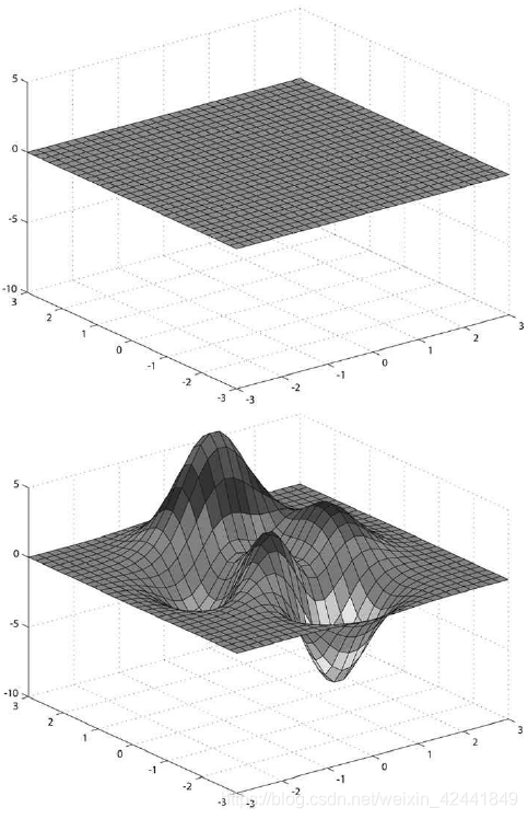
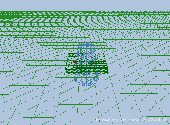
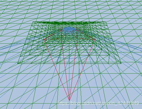
7 陆地和波浪示例
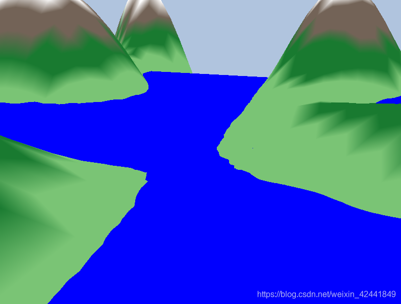
该图是一个基于实数方程y = f(x, z)的平面,我们可以通过生成一个xz平面(每个方格由2个三角形组成),然后再将每个顶点套入上述方程后近似得到。
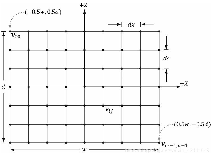
7.1 创建网格顶点
一个m × n的网格包含(m – 1) × (n – 1)个四边形,每个四边形包含2个三角形,所以总共就有2 (m – 1) × (n – 1)个三角形。如果网格的宽度是w,深度是d,那么每个四边形在x轴方向的长度是dx = w/(n – 1),在z轴方向就是dz = d/(m − 1)。所以我们从左上角开始创建,那么第ijth个顶点的坐标就是:

其创建代码如下:
GeometryGenerator::MeshData GeometryGenerator::CreateGrid(float width, float depth, uint32 m, uint32 n)
{
	MeshData meshData;
	uint32 vertexCount = m*n;
	uint32 faceCount = (m-1)*(n-1)*2;
	float halfWidth = 0.5f*width;
	float halfDepth = 0.5f*depth;
	float dx = width / (n-1);
	float dz = depth / (m-1);
	float du = 1.0f / (n-1);
	float dv = 1.0f / (m-1);
	meshData.Vertices.resize(vertexCount);

	for(uint32 i = 0; i < m; ++i)
	{
		float z = halfDepth - i*dz;
		for(uint32 j = 0; j < n; ++j)
		{
			float x = -halfWidth + j*dx;
			meshData.Vertices[i*n+j].Position = XMFLOAT3(x, 0.0f, z);
			meshData.Vertices[i*n+j].Normal = XMFLOAT3(0.0f, 1.0f, 0.0f);
			meshData.Vertices[i*n+j].TangentU = XMFLOAT3(1.0f, 0.0f, 0.0f);

			// Stretch texture over grid.
			meshData.Vertices[i*n+j].TexC.x = j*du;
			meshData.Vertices[i*n+j].TexC.y = i*dv;
		}
	}
}
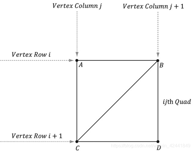
7.2 创建网格索引
从左上角开始遍历每个四边形,用索引生成2个三角形:
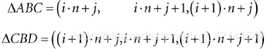
生成索引的代码如下:
	meshData.Indices32.resize(faceCount*3); // 3 indices per face
	// Iterate over each quad and compute indices.
	uint32 k = 0;

	for(uint32 i = 0; i < m-1; ++i)
	{
		for(uint32 j = 0; j < n-1; ++j)
		{
			meshData.Indices32[k] = i*n+j;
			meshData.Indices32[k+1] = i*n+j+1;
			meshData.Indices32[k+2] = (i+1)*n+j;
			meshData.Indices32[k+3] = (i+1)*n+j;
			meshData.Indices32[k+4] = i*n+j+1;
			meshData.Indices32[k+5] = (i+1)*n+j+1;
			k += 6; // next quad
		}
	}
	return meshData;
}
7.3 应用高度计算方程
创建好网格后,我们可以从MeshData中提取出顶点数据,转换成高度不同的表面来表示山脉,然后再根据高度赋予不同的颜色:
// Not to be confused with GeometryGenerator::Vertex.
struct Vertex
{
	XMFLOAT3 Pos;
	XMFLOAT4 Color;
};
void LandAndWavesApp::BuildLandGeometry()
{
	GeometryGenerator geoGen;
	GeometryGenerator::MeshData grid = geoGen.CreateGrid(160.0f, 160.0f, 50, 50);

	//
	// Extract the vertex elements we are interested and apply the height
	// function to each vertex. In addition, color the vertices based on
	// their height so we have sandy looking beaches, grassy low hills,
	// and snow mountain peaks.
	//

	std::vector<Vertex> vertices(grid.Vertices.size());
	for(size_t i = 0; i < grid.Vertices.size(); ++i)
	{
		auto& p = grid.Vertices[i].Position;
		vertices[i].Pos = p;
		vertices[i].Pos.y = GetHillsHeight(p.x, p.z);

		// Color the vertex based on its height.
		if(vertices[i].Pos.y < -10.0f)
		{
			// Sandy beach color.
			vertices[i].Color = XMFLOAT4(1.0f, 0.96f, 0.62f, 1.0f);
		}
		else if(vertices[i].Pos.y < 5.0f)
		{
			// Light yellow-green.
			vertices[i].Color = XMFLOAT4(0.48f, 0.77f, 0.46f, 1.0f);
		}
		else if(vertices[i].Pos.y < 12.0f)
		{
			// Dark yellow-green.
			vertices[i].Color = XMFLOAT4(0.1f, 0.48f, 0.19f, 1.0f);
		}
		else if(vertices[i].Pos.y < 20.0f)
		{
			// Dark brown.
			vertices[i].Color = XMFLOAT4(0.45f, 0.39f, 0.34f, 1.0f);
		}
		else
		{
			// White snow.
			vertices[i].Color = XMFLOAT4(1.0f, 1.0f, 1.0f, 1.0f);
		}
	}

	const UINT vbByteSize = (UINT)vertices.size() * sizeof(Vertex);

	std::vector<std::uint16_t> indices = grid.GetIndices16();
	const UINT ibByteSize = (UINT)indices.size() * sizeof(std::uint16_t);

	auto geo = std::make_unique<MeshGeometry>();
	geo->Name = "landGeo";
	ThrowIfFailed(D3DCreateBlob(vbByteSize, &geo->VertexBufferCPU));
	CopyMemory(geo->VertexBufferCPU->GetBufferPointer(), vertices.data(), vbByteSize);
	ThrowIfFailed(D3DCreateBlob(ibByteSize, &geo->IndexBufferCPU));
	CopyMemory(geo->IndexBufferCPU->GetBufferPointer(), indices.data(), ibByteSize);

	geo->VertexBufferGPU = d3dUtil::CreateDefaultBuffer(md3dDevice.Get(),
		mCommandList.Get(), vertices.data(),
		vbByteSize, geo->VertexBufferUploader);
	geo->IndexBufferGPU = d3dUtil::CreateDefaultBuffer(md3dDevice.Get(),
		mCommandList.Get(), indices.data(),
		ibByteSize, geo->IndexBufferUploader);

	geo->VertexByteStride = sizeof(Vertex);
	geo->VertexBufferByteSize = vbByteSize;
	geo->IndexFormat = DXGI_FORMAT_R16_UINT;
	geo->IndexBufferByteSize = ibByteSize;

	SubmeshGeometry submesh;
	submesh.IndexCount = (UINT)indices.size();
	submesh.StartIndexLocation = 0;
	submesh.BaseVertexLocation = 0;
	geo->DrawArgs["grid"] = submesh;
	mGeometries["landGeo"] = std::move(geo);
}
本Demo中的函数f(x, z)实现如下:
float LandAndWavesApp::GetHeight(float x, float z)const
{
	return 0.3f*(z*sinf(0.1f*x) + x*cosf(0.1f*z));
}
7.4 根CBVs
另一个和Shape Demo不同的地方在于,我们使用根描述所以CBV可以直接绑定而不需要描述堆:
- 根签名需要2个根CBV而不是两个描述表;
- 不需要描述堆;
- 新的语法来绑定根描述。
// Root parameter can be a table, root descriptor or root constants.
CD3DX12_ROOT_PARAMETER slotRootParameter[2];

// Create root CBV.
slotRootParameter[0].InitAsConstantBufferView(0);
// per-object CBV
slotRootParameter[1].InitAsConstantBufferView(1);
// per-pass CBV

// A root signature is an array of root parameters.
CD3DX12_ROOT_SIGNATURE_DESC rootSigDesc(2,
	slotRootParameter, 0,
	nullptr,
	D3D12_ROOT_SIGNATURE_FLAG_ALLOW_INPUT_ASSEMBLER_INPUT_LAYOUT);
InitAsConstantBufferView方法参数是寄存器序号。
现在我们使用下面的方法来以参数的形式绑定CBV到根描述:
void ID3D12GraphicsCommandList::SetGraphicsRootConstantBufferView(
	UINT RootParameterIndex,
	D3D12_GPU_VIRTUAL_ADDRESS BufferLocation);
- RootParameterIndex:绑定的根参数的索引;
- BufferLocation:常量缓冲资源的虚拟地址。
修改后,我们的绘制代码如下:
void LandAndWavesApp::Draw(const GameTimer& gt)
{
	[…]
	// Bind per-pass constant buffer. We only need to do this once per-pass.
	auto passCB = mCurrFrameResource->PassCB->Resource();
	mCommandList->SetGraphicsRootConstantBufferView(1, passCB->GetGPUVirtualAddress());
	DrawRenderItems(mCommandList.Get(), mRitemLayer[(int)RenderLayer::Opaque]);
	[…]
}

void LandAndWavesApp::DrawRenderItems(
	ID3D12GraphicsCommandList* cmdList,
	const std::vector<RenderItem*>& ritems)
{
	UINT objCBByteSize = d3dUtil::CalcConstantBufferByteSize(sizeof(ObjectConstants));
	auto objectCB = mCurrFrameResource->ObjectCB->Resource();

	// For each render item…
	for(size_t i = 0; i < ritems.size(); ++i)
	{
		auto ri = ritems[i];
		cmdList->IASetVertexBuffers(0, 1, &ri->Geo->VertexBufferView());
		cmdList->IASetIndexBuffer(&ri->Geo->IndexBufferView());
		cmdList->IASetPrimitiveTopology(ri->PrimitiveType);

		D3D12_GPU_VIRTUAL_ADDRESS objCBAddress = objectCB->GetGPUVirtualAddress();
		objCBAddress += ri->ObjCBIndex*objCBByteSize;
		cmdList->SetGraphicsRootConstantBufferView(0, objCBAddress);

		cmdList->DrawIndexedInstanced(ri->IndexCount,
			1,
			ri->StartIndexLocation, ri->BaseVertexLocation, 0);
	}
}
7.5 动态顶点缓冲
我们之前已经使用过每帧从CPU上传常量缓冲数据到GPU,我们可以使用UploadBuffer类利用同样的技术上传顶点数组,来动态模拟水面:
std::unique_ptr<UploadBuffer<Vertex>> WavesVB = nullptr;
WavesVB = std::make_unique<UploadBuffer<Vertex>>(device, waveVertCount, false);
因为我们每帧需要从CPU上传新的顶点缓冲,所以它需要成为一个帧资源。否则我们可能会改写GPU没有执行到的数据。
每一帧我们执行播放模拟和更新的顶点缓冲代码如下:
void LandAndWavesApp::UpdateWaves(const GameTimer& gt)
{
	// Every quarter second, generate a random wave.
	static float t_base = 0.0f;

	if((mTimer.TotalTime() - t_base) >= 0.25f)
	{
		t_base += 0.25f;
		int i = MathHelper::Rand(4, mWaves->RowCount() - 5);
		int j = MathHelper::Rand(4, mWaves->ColumnCount() - 5);
		float r = MathHelper::RandF(0.2f, 0.5f);
		mWaves->Disturb(i, j, r);
	}

	// Update the wave simulation.
	mWaves->Update(gt.DeltaTime());

	// Update the wave vertex buffer with the new solution.
	auto currWavesVB = mCurrFrameResource->WavesVB.get();
	for(int i = 0; i < mWaves->VertexCount(); ++i)
	{
		Vertex v;
		v.Pos = mWaves->Position(i);
		v.Color = XMFLOAT4(DirectX::Colors::Blue);
		currWavesVB->CopyData(i, v);
	}

	// Set the dynamic VB of the wave renderitem to the current frame VB.
	mWavesRitem->Geo->VertexBufferGPU = currWavesVB->Resource();
}
使用动态缓冲会有一些额外开销,因为新数据需要从CPU不断上传到GPU。所以静态缓冲比动态缓冲更好。前一个版本的D3D介绍了一些新特征来减少动态缓冲的使用:
- 简单的动画使用顶点着色器实现;
- 如果可以的话通过渲染到贴图、计算着色器、和顶点贴图获取功能来实现波浪模拟;让这些运算完全在GPU上执行;
- 几何着色器可以实现在GPU上创建或者销毁基元(没有它的时候这些任务只能在CPU上实现);
- 曲面细分阶段可以在GPU细分曲面(没有它的时候这些任务只能在CPU上实现)。
索引缓冲也可以使用动态缓冲,因为本Demo中拓扑结构不变,所以不需要。
本书并不对波浪的实现算法进行细入分析(可以看[Lengyel02]),但是会更多的描述动态缓冲:在CPU动态模拟然后使用上传缓冲上传到GPU。
8 总结
- 等待GPU执行完所有命令是一个很低效的事情,因为GPU和CPU都会产生等待的时间;一个更高效的方法是创建帧资源(frame resources)------一个环形数组的资源,CPU需要修改所有资源。这样CPU不需要再等待GPU执行完毕,可以直接修改下一个可修改的资源。但是如果CPU一直执行过快,CPU还是可能产生等到GPU的时间;不过大部分情况下这是值得的,因为首先可以保证GPU满负荷运转,CPU空余出来的时候可以进行其它模块的计算,比如AI、物理和游戏逻辑等。
- 我们可以通过下面的函数获取描述堆中第一个的句柄ID3D12DescriptorHeap::GetCPUDescriptorHandleForHeapStart;然后可以通过下面的方法获取描述的大小:ID3D12Device::GetDescriptorHandleIncrementSize(DescriptorHeapType type)。然后通过下面的方法来偏移到我们需要的描述位置:CD3DX12_CPU_DESCRIPTOR_HANDLE::Offset:
// Specify the number of descriptors to offset times the descriptor
// increment size:
D3D12_CPU_DESCRIPTOR_HANDLE handle = mCbvHeap->GetCPUDescriptorHandleForHeapStart();
handle.Offset(n * mCbvSrvDescriptorSize);

// Or equivalently, specify the number of descriptors to offset,
// followed by the descriptor increment size:
D3D12_CPU_DESCRIPTOR_HANDLE handle = mCbvHeap->GetCPUDescriptorHandleForHeapStart();
handle.Offset(n, mCbvSrvDescriptorSize);

//The CD3DX12_GPU_DESCRIPTOR_HANDLE type has the same Offset methods.
- 根签名定义了在一个绘制调用前那些资源要被绑定到渲染管线和这些资源是如何被绑定到着色器寄存器中的。哪些资源会被绑定取决于着色器程序的预期。当PSO被创建时,根签名和着色器程序组合会被验证。一个根签名由一组根参数来定义。一个根参数可以是描述表,根描述或者根常量。一个描述表定义了一段在描述堆中连续的范围;根描述用以直接绑定一个描述到根签名;根常量用以直接绑定常量数据到根签名。为了性能,根签名最多只能放64 DWORDs的上限,描述表占用1DWORD;根描述占用2DWORD;根常量每32位占用1DWORD。在每个绘制调用时,硬件自动为每个根参数对象保存快照(版本管理),所以我们需要尽可能减少根签名的大小来节约内存占用。
- 动态顶点缓冲用来当常量顶点缓冲需要频繁更新和上传的时候。我们可以使用UploadBuffer来视线动态顶点缓冲。因为我们需要上传新内容到GPU,所以动态顶点缓冲需要放到帧资源中。使用动态顶点缓冲时会有一些新的开销,因为需要将数据从CPU传到GPU。静态顶点缓冲比动态的更实用,前一个版本的D3D提供了一些新特性来减少使用动态缓冲。
9 练习
-
修改“Shape” Demo,使用GeometryGenerator::CreateGeosphere代替GeometryGenerator::CreateSphere,并尝试0、1、2、3细分等级;
代码在 https://github.com/jiabaodan/Direct12BookReadingNotes 中的 Chapter7_Exercises_1_Geosphere 工程
替换创建函数即可 -
修改“Shape” Demo,使用16个根常量替换描述表来设置每个物体的世界坐标变换矩阵;
代码在 https://github.com/jiabaodan/Direct12BookReadingNotes 中的 Chapter7_Exercises_2_RootConstants 工程
修改为使用Root Constant即可
CD3DX12_ROOT_PARAMETER slotRootParameter[2];
slotRootParameter[0].InitAsConstants(16, 0);

// 设置Root Constant's values
DirectX::XMFLOAT4X4 WorldTest = MathHelper::Identity4x4();
XMStoreFloat4x4(&WorldTest,
	XMMatrixTranslation(0.0f, 2.0f, 0.0f) *
	XMMatrixRotationX(0.f) *
	XMMatrixScaling(2.0f, 1.0f, 2.0f));
mCommandList->SetGraphicsRoot32BitConstants(0, 16, WorldTest.m, 0);
但是这样做后会有2个问题:1、没办法针对每个物体设置值;2、进行位移设置后,物体会显示错误
针对上面的问题和BUG目前没有找到解决方案,如果有大佬看到的话希望指点下,谢谢哈~
- 在本书的光盘中有一个Models/Skull.txt文件,它包含了一个骷髅头模型所需要的顶点和索引列表数据。使用文本编辑器来学习这个文件然后修改“Shape” Demo来加载骷髅头网格。