学习目标
- 熟悉环境光遮蔽的基本思路,以及通过光线跟踪的实现方法;
- 学习如何在屏幕坐标系下实现实时模拟的环境光遮蔽。
1 通过光线追踪实现的环境光遮蔽

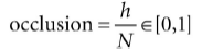
其中一种估算点P遮蔽的方法是光线跟踪。我们随机跟踪点P半圆内的光线,然后查看和网格相交的光线。如果跟踪了N条光线,相交了h条,那么点P的遮蔽值为:
只有交点q到p的距离小于某个入口距离d才能贡献遮蔽估算;因为如果p和q的距离过远的话,就无法遮挡。

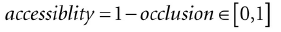
遮挡因子代表了点P有多闭塞,而为了计算为目的,我们需要知道点P能接收到多少光,我们叫它可达性(accessibility),它由遮挡值计算得到:
下面的代码计算了逐三角形的光线追踪,结果通过三角形三个顶点的平均值计算得到。光线的原点是三角形的中点,然后在半圆范围了随机创建射线:
void AmbientOcclusionApp::BuildVertexAmbientOcclusion(
	std::vector<Vertex::AmbientOcclusion>& vertices,
	const std::vector<UINT>& indices)
{
	UINT vcount = vertices.size();
	UINT tcount = indices.size()/3;
	std::vector<XMFLOAT3> positions(vcount);

	for(UINT i = 0; i < vcount; ++i)
		positions[i] = vertices[i].Pos;

	Octree octree;
	octree.Build(positions, indices);

	// For each vertex, count how many triangles contain the vertex.
	std::vector<int> vertexSharedCount(vcount);

	// Cast rays for each triangle, and average triangle occlusion
	// with the vertices that share this triangle.
	for(UINT i = 0; i < tcount; ++i)
	{
		UINT i0 = indices[i*3+0];
		UINT i1 = indices[i*3+1];
		UINT i2 = indices[i*3+2];
		XMVECTOR v0 = XMLoadFloat3(&vertices[i0].Pos);
		XMVECTOR v1 = XMLoadFloat3(&vertices[i1].Pos);
		XMVECTOR v2 = XMLoadFloat3(&vertices[i2].Pos);
		XMVECTOR edge0 = v1 - v0;
		XMVECTOR edge1 = v2 - v0;
		XMVECTOR normal = XMVector3Normalize(XMVector3Cross(edge0, edge1));
		XMVECTOR centroid = (v0 + v1 + v2)/3.0f;

		// Offset to avoid self intersection.
		centroid += 0.001f*normal;
		const int NumSampleRays = 32;
		float numUnoccluded = 0;

		for(int j = 0; j < NumSampleRays; ++j)
		{
			XMVECTOR randomDir = MathHelper::RandHemisphereUnitVec3(normal);

			// Test if the random ray intersects the scene mesh.
			//
			// TODO: Technically we should not count intersections
			// that are far away as occluding the triangle, but
			// this is OK for demo.
			if( !octree.RayOctreeIntersect(centroid, randomDir) )
			{
			 	numUnoccluded++;
			}
		}

		float ambientAccess = numUnoccluded / NumSampleRays;

		// Average with vertices that share this face.
		vertices[i0].AmbientAccess += ambientAccess;
		vertices[i1].AmbientAccess += ambientAccess;
		vertices[i2].AmbientAccess += ambientAccess;
		vertexSharedCount[i0]++;
		vertexSharedCount[i1]++;
		vertexSharedCount[i2]++;
	}

	// Finish average by dividing by the number of samples we added,
	// and store in the vertex attribute.
	for(UINT i = 0; i < vcount; ++i)
	{
		vertices[i].AmbientAccess /= vertexSharedCount[i];
	}
}
本Demo使用了八叉树(octree)进行射线/三角形相交检测。因为网格可能有成千上万个三角形,逐三角形进行射线检测计算量非常大,八叉树对三角形在空间上排序,这样就可以检测最有机会相交的三角形,这样就减少了相交检测。八叉树是一个空间的数据结构。

上图是使用上面算法实现的屏幕截图,它进行了环境光遮蔽的预计算,然后保存到顶点结构中。(场景中没有灯光)
预计算的环境光遮蔽对于静态的模型来说可以有很好的效果,甚至有一些工具(http://www.xnormal.net)来创建环境光遮蔽贴图–纹理来保存环境光遮蔽数据。但是对于运动的模型就无法实现(计算量太大)。
2 屏幕空间环境光遮蔽
屏幕空间环境光遮蔽(screen space ambient occlusion (SSAO))的策略是:对每一帧,在视景空间下,渲染法线到一个渲染目标,然后渲染深度值到深度/模板缓冲中;然后使用上面2张计算的纹理来模拟逐像素的模拟环境光遮蔽;当我们有了环境光遮蔽的纹理,我们进行正常的渲染到后置缓冲中,但是要以SSAO数据对每个像素进行环境光遮蔽处理。
2.1 渲染法线和深度值
首先我们渲染法线到屏幕尺寸,DXGI_FORMAT_R16G16B16A16_FLOAT格式的纹理中,并且在深度/模板缓冲中渲染深度值,着色器代码如下:
// Include common HLSL code.
#include “Common.hlsl”

struct VertexIn
{
	float3 PosL : POSITION;
	float3 NormalL : NORMAL;
	float2 TexC : TEXCOORD;
	float3 TangentU : TANGENT;
};

struct VertexOut
{
	float4 PosH : SV_POSITION;
	float3 NormalW : NORMAL;
	float3 TangentW : TANGENT;
	float2 TexC : TEXCOORD;
};

VertexOut VS(VertexIn vin)
{
	VertexOut vout = (VertexOut)0.0f;

	// Fetch the material data.
	MaterialData matData = gMaterialData[gMaterialIndex];

	// Assumes nonuniform scaling; otherwise, need to use
	// inverse-transpose of world matrix.
	vout.NormalW = mul(vin.NormalL, (float3x3)gWorld);
	vout.TangentW = mul(vin.TangentU, (float3x3)gWorld);

	// Transform to homogeneous clip space.
	float4 posW = mul(float4(vin.PosL, 1.0f), gWorld);
	vout.PosH = mul(posW, gViewProj);
	float4 texC = mul(float4(vin.TexC, 0.0f, 1.0f), gTexTransform);
	vout.TexC = mul(texC, matData.MatTransform).xy;

	return vout;
}

float4 PS(VertexOut pin) : SV_Target
{
	// Fetch the material data.
	MaterialData matData = gMaterialData[gMaterialIndex];
	float4 diffuseAlbedo = matData.DiffuseAlbedo;
	uint diffuseMapIndex = matData.DiffuseMapIndex;
	uint normalMapIndex = matData.NormalMapIndex;

	// Dynamically look up the texture in the array.
	diffuseAlbedo *= gTextureMaps[diffuseMapIndex].Sample(gsamAnisotropicWrap, pin.TexC);

	#ifdef ALPHA_TEST
		// Discard pixel if texture alpha < 0.1. We do this test as soon
		// as possible in the shader so that we can potentially exit the
		// shader early, thereby skipping the rest of the shader code.
		clip(diffuseAlbedo.a - 0.1f);
	#endif

	// Interpolating normal can unnormalize it, so renormalize it.
	pin.NormalW = normalize(pin.NormalW);

	// NOTE: We use interpolated vertex normal for SSAO.
	// Write normal in view space coordinates
	float3 normalV = mul(pin.NormalW, (float3x3)gView);

	return float4(normalV, 0.0f);
}
像素着色器输出视景坐标系下的法线向量。因为我们渲染到一个浮点数的渲染目标,所以返回浮点数是没有问题的。
2.2 环境光遮蔽Pass
当我们渲染好视景坐标系下的法线和深度时,我们禁用深度缓冲;然后对屏幕每个点调用SSAP像素着色器,计算出每个像素的环境光可访问值,我们叫这张纹理为SSAP贴图。虽然我们的法线/深度图都是全屏幕分辨率的,但是为了性能,SSAP贴图使用半分辨率:

2.2.1 重建视景空间位置
当我们调用SSAO像素着色器绘制全屏幕的每个像素时,我们可以使用投影矩阵的逆矩阵将四边形的四个顶点变换到NDC空间的近平面窗口上:
static const float2 gTexCoords[6] =
{
	float2(0.0f, 1.0f),
	float2(0.0f, 0.0f),
	float2(1.0f, 0.0f),
	float2(0.0f, 1.0f),
	float2(1.0f, 0.0f),
	float2(1.0f, 1.0f)
};

// Draw call with 6 vertices
VertexOut VS(uint vid : SV_VertexID)
{
	VertexOut vout;
	vout.TexC = gTexCoords[vid];

	// Quad covering screen in NDC space.
	vout.PosH = float4(2.0f*vout.TexC.x - 1.0f,
		1.0f - 2.0f*vout.TexC.y, 0.0f, 1.0f);

	// Transform quad corners to view space near plane.
	float4 ph = mul(vout.PosH, gInvProj);
	vout.PosV = ph.xyz / ph.w;

	return vout;
}
到近平面的向量通过差值计算得到,并且得到眼睛到每个像素的向量v。现在对于每个像素,我们对深度值采样,得到在NDC坐标系距离眼睛最近的像素的z坐标,目的是重建世界坐标系下的位置p = (px, py, pz),然后差值得到向量。重建的着色器代码如下:
float NdcDepthToViewDepth(float z_ndc)
{
	// We can invert the calculation from NDC space to view space for the
	// z-coordinate. We have that
	// z_ndc = A + B/viewZ, where gProj[2,2]=A and gProj[3,2]=B.
	// Therefore…
	float viewZ = gProj[3][2] / (z_ndc - gProj[2][2]);

	return viewZ;
}

float4 PS(VertexOut pin) : SV_Target
{
	// Get z-coord of this pixel in NDC space from depth map.
	float pz = gDepthMap.SampleLevel(gsamDepthMap, pin.TexC, 0.0f).r;

	// Transform depth to view space.
	pz = NdcDepthToViewDepth(pz);

	// Reconstruct the view space position of the point with depth pz.
	float3 p = (pz/pin.PosV.z)*pin.PosV;

	[…]
}
2.2.2 创建随机采样
这一步和光线追踪算法中半球体随机射线的思路一样。在我们的Demo中。下面的问题是,如何随机采样,我们可以先随机向量并保存到一张纹理中,然后对纹理进行采样;但是这会导致有一定几率随机到的向量都是在一个小方向范围内,就导致遮蔽计算不正确。所以我们采样下面的方法,采样14次:
void Ssao::BuildOffsetVectors()
{
	// Start with 14 uniformly distributed vectors. We choose the
	// 8 corners of the cube and the 6 center points along each
	// cube face. We always alternate the points on opposite sides
	// of the cubes. This way we still get the vectors spread out
	// even if we choose to use less than 14 samples.
	// 8 cube corners
	mOffsets[0] = XMFLOAT4(+1.0f, +1.0f, +1.0f, 0.0f);
	mOffsets[1] = XMFLOAT4(-1.0f, -1.0f, -1.0f, 0.0f);
	mOffsets[2] = XMFLOAT4(-1.0f, +1.0f, +1.0f, 0.0f);
	mOffsets[3] = XMFLOAT4(+1.0f, -1.0f, -1.0f, 0.0f);
	mOffsets[4] = XMFLOAT4(+1.0f, +1.0f, -1.0f, 0.0f);
	mOffsets[5] = XMFLOAT4(-1.0f, -1.0f, +1.0f, 0.0f);
	mOffsets[6] = XMFLOAT4(-1.0f, +1.0f, -1.0f, 0.0f);
	mOffsets[7] = XMFLOAT4(+1.0f, -1.0f, +1.0f, 0.0f);

	// 6 centers of cube faces
	mOffsets[8] = XMFLOAT4(-1.0f, 0.0f, 0.0f, 0.0f);
	mOffsets[9] = XMFLOAT4(+1.0f, 0.0f, 0.0f, 0.0f);
	mOffsets[10] = XMFLOAT4(0.0f, -1.0f, 0.0f, 0.0f);
	mOffsets[11] = XMFLOAT4(0.0f, +1.0f, 0.0f, 0.0f);
	mOffsets[12] = XMFLOAT4(0.0f, 0.0f, -1.0f, 0.0f);
	mOffsets[13] = XMFLOAT4(0.0f, 0.0f, +1.0f, 0.0f);

	for(int i = 0; i < 14; ++i)
	{
		// Create random lengths in [0.25, 1.0].
		float s = MathHelper::RandF(0.25f, 1.0f);
		XMVECTOR v = s * XMVector4Normalize(XMLoadFloat4(&mOffsets[i]));
		XMStoreFloat4(&mOffsets[i], v);
	}
}
2.2.3 创建可能遮挡的点
现在我们有随机采样点q包围p,但是我们目前并不知道它们在空空间还是物体里面。所以我们对每个q创建透视纹理坐标,然后对深度缓冲进行采样,得到NDC的深度值并变换到视景坐标系下面;这样我们就可以重建完整的3D视景空间。这些变换后的点r就都是潜在的遮挡点。
2.2.4 执行遮挡测试
现在有了潜在遮挡点r,可以按照下面步骤进行遮挡测试:
1、视景空间深度距离|pz − rz|;我们随着距离的增加,线性缩小遮挡值;如果距离超过最大值,遮挡值为0;并且如果距离特别小,代表p和q在同一个平面,表示也没有遮挡值;
2、n和r - p的夹角通过下面的公式来计算:
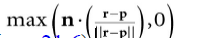

从上图可以看出 r和p的距离足够小,表示r遮挡p,但是他们在同一个平面上,r并不遮挡p;所以计算夹角可以排除上述的问题。
2.2.5 完成计算
对每个采样相加后,我们通过除以采样次数求出遮挡平均值,然后我们计算遮挡访问值(mbient-access),最终通过加权来增加对比度。你也许也希望增加亮度或者强度:
occlusionSum /= gSampleCount;
float access = 1.0f - occlusionSum;

// Sharpen the contrast of the SSAO map to make the SSAO affect more dramatic.
return saturate(pow(access, 4.0f));
2.2.6 实现
前面的小节介绍了创建SSAO的主要步骤,下面是HLSL的实现代码:
//====================================================================
// Ssao.hlsl by Frank Luna (C) 2015 All Rights Reserved.
//====================================================================

cbuffer cbSsao : register(b0)
{
	float4x4 gProj;
	float4x4 gInvProj;
	float4x4 gProjTex;
	float4 gOffsetVectors[14];

	// For SsaoBlur.hlsl
	float4 gBlurWeights[3];
	float2 gInvRenderTargetSize;

	// Coordinates given in view space.
	float gOcclusionRadius;
	float gOcclusionFadeStart;
	float gOcclusionFadeEnd;
	float gSurfaceEpsilon;
};

cbuffer cbRootConstants : register(b1)
{
	bool gHorizontalBlur;
};

// Nonnumeric values cannot be added to a cbuffer.
Texture2D gNormalMap : register(t0);
Texture2D gDepthMap : register(t1);
Texture2D gRandomVecMap : register(t2);
SamplerState gsamPointClamp : register(s0);
SamplerState gsamLinearClamp : register(s1);
SamplerState gsamDepthMap : register(s2);
SamplerState gsamLinearWrap : register(s3);

static const int gSampleCount = 14;
static const float2 gTexCoords[6] =
{
	float2(0.0f, 1.0f),
	float2(0.0f, 0.0f),
	float2(1.0f, 0.0f),
	float2(0.0f, 1.0f),
	float2(1.0f, 0.0f),
	float2(1.0f, 1.0f)
};

struct VertexOut
{
	float4 PosH : SV_POSITION;
	float3 PosV : POSITION;
	float2 TexC : TEXCOORD0;
};

VertexOut VS(uint vid : SV_VertexID)
{
	VertexOut vout;
	vout.TexC = gTexCoords[vid];

	// Quad covering screen in NDC space.
	vout.PosH = float4(2.0f*vout.TexC.x - 1.0f, 1.0f - 2.0f*vout.TexC.y, 0.0f, 1.0f);

	// Transform quad corners to view space near plane.
	float4 ph = mul(vout.PosH, gInvProj);
	vout.PosV = ph.xyz / ph.w;

	return vout;
}

// Determines how much the sample point q occludes the point p as a function
// of distZ.
float OcclusionFunction(float distZ)
{
	//
	// If depth(q) is “behind” depth(p), then q cannot occlude p. Moreover, if
	// depth(q) and depth(p) are sufficiently close, then we also assume q cannot
	// occlude p because q needs to be in front of p by Epsilon to occlude p.
	//
	// We use the following function to determine the occlusion.
	//
	//
	// 1.0 -------------\
	// | | \
	// | | \
	// | | \
	// | | \
	// | | \
	// | | \
	// ------|------|-----------|-------------|---- -----|--> zv
	// 0 Eps z0 z1
	//
	float occlusion = 0.0f;
	if(distZ > gSurfaceEpsilon)
	{
		float fadeLength = gOcclusionFadeEnd - gOcclusionFadeStart;

		// Linearly decrease occlusion from 1 to 0 as distZ goes
		// from gOcclusionFadeStart to gOcclusionFadeEnd.
		occlusion = saturate( (gOcclusionFadeEnddistZ)/ fadeLength );
	}

	return occlusion;
}

float NdcDepthToViewDepth(float z_ndc)
{
	// z_ndc = A + B/viewZ, where gProj[2,2]=A and gProj[3,2]=B.
	float viewZ = gProj[3][2] / (z_ndc - gProj[2][2]);

	return viewZ;
}

float4 PS(VertexOut pin) : SV_Target
{
	// p -- the point we are computing the ambient occlusion for.
	// n -- normal vector at p.
	// q -- a random offset from p.
	// r -- a potential occluder that might occlude p.
	// Get viewspace normal and z-coord of this pixel.
	float3 n = gNormalMap.SampleLevel(gsamPointClamp, pin.TexC, 0.0f).xyz;
	float pz = gDepthMap.SampleLevel(gsamDepthMap, pin.TexC, 0.0f).r;
	pz = NdcDepthToViewDepth(pz);

	//
	// Reconstruct full view space position (x,y,z).
	// Find t such that p = t*pin.PosV.
	// p.z = t*pin.PosV.z
	// t = p.z / pin.PosV.z
	//
	float3 p = (pz/pin.PosV.z)*pin.PosV;

	// Extract random vector and map from [0,1] --> [-1, +1].
	float3 randVec = 2.0f*gRandomVecMap.SampleLevel(
		gsamLinearWrap, 4.0f*pin.TexC, 0.0f).rgb - 1.0f;
	float occlusionSum = 0.0f;

	// Sample neighboring points about p in the hemisphere oriented by n.
	for(int i = 0; i < gSampleCount; ++i)
	{
		// Are offset vectors are fixed and uniformly distributed (so that
		// our offset vectors do not clump in the same direction). If we
		// reflect them about a random vector then we get a random uniform
		// distribution of offset vectors.
		float3 offset = reflect(gOffsetVectors[i].xyz, randVec);

		// Flip offset vector if it is behind the plane defined by (p, n).
		float flip = sign( dot(offset, n) );

		// Sample a point near p within the occlusion radius.
		float3 q = p + flip * gOcclusionRadius * offset;

		// Project q and generate projective texcoords.
		float4 projQ = mul(float4(q, 1.0f), gProjTex);
		projQ /= projQ.w;

		// Find the nearest depth value along the ray from the eye to q
		// (this is not the depth of q, as q is just an arbitrary point
		// near p and might occupy empty space). To find the nearest depth
		// we look it up in the depthmap.
		float rz = gDepthMap.SampleLevel(gsamDepthMap, projQ.xy, 0.0f).r;
		rz = NdcDepthToViewDepth(rz);

		// Reconstruct full view space position r = (rx,ry,rz). We know r
		// lies on the ray of q, so there exists a t such that r = t*q.
		// r.z = t*q.z ==> t = r.z / q.z
		float3 r = (rz / q.z) * q;

		//
		// Test whether r occludes p.
		// * The product dot(n, normalize(r - p)) measures how much in
		// front of the plane(p,n) the occluder point r is. The more in
		// front it is, the more occlusion weight we give it. This also
		// prevents self shadowing where a point r on an angled plane (p,n)
		// could give a false occlusion since they have different depth
		// values with respect to the eye.
		// * The weight of the occlusion is scaled based on how far the
		// occluder is from the point we are computing the occlusion of. If
		// the occluder r is far away from p, then it does not occlude it.
		//
		float distZ = p.z - r.z;
		float dp = max(dot(n, normalize(r - p)), 0.0f);
		float occlusion = dp * OcclusionFunction(distZ);

		occlusionSum += occlusion;
	}

	occlusionSum /= gSampleCount;
	float access = 1.0f - occlusionSum;

	// Sharpen the contrast of the SSAO map to make the SSAO affect more
	// dramatic.
	return saturate(pow(access, 2.0f));
}

对于距离很大的场景,因为深度缓冲的精度限制,可能导致渲染错误。一个简单的方案是随着距离,让SSAO的效果淡出。
2.3 模糊Pass
上图可以看出现在环境光遮蔽的效果,噪点是因为采样数量有限;如果采样足够多,对于实时程序来说性能无法满足。通用的方案是对SSAO贴图进行边缘保留模糊(edge preserving blur (i.e., bilateral blur))。如果使用非边缘保留模糊(non-edge preserving blur)我们会丢失场景清晰度,明显的边缘会消失。边缘保留模糊基本思路和我们第13章中实现的一样,只是多加个条件,对边缘不模糊(边缘通过深度/法线贴图判定):
//====================================================================
// SsaoBlur.hlsl by Frank Luna (C) 2015 All Rights Reserved.
//
// Performs a bilateral edge preserving blur of the ambient map. We use
// a pixel shader instead of compute shader to avoid the switch from
// compute mode to rendering mode. The texture cache makes up for some
// of the loss of not having shared memory. The ambient map uses 16-bit
// texture format, which is small, so we should be able to fit a lot of
// texels in the cache.
//=====================================================================
cbuffer cbSsao : register(b0)
{
	float4x4 gProj;
	float4x4 gInvProj;
	float4x4 gProjTex;
	float4 gOffsetVectors[14];

	// For SsaoBlur.hlsl
	float4 gBlurWeights[3];
	float2 gInvRenderTargetSize;

	// Coordinates given in view space.
	float gOcclusionRadius;
	float gOcclusionFadeStart;
	float gOcclusionFadeEnd;
	float gSurfaceEpsilon;
};

cbuffer cbRootConstants : register(b1)
{
	bool gHorizontalBlur;
};

// Nonnumeric values cannot be added to a cbuffer.
Texture2D gNormalMap : register(t0);
Texture2D gDepthMap : register(t1);
Texture2D gInputMap : register(t2);

SamplerState gsamPointClamp : register(s0);
SamplerState gsamLinearClamp : register(s1);
SamplerState gsamDepthMap : register(s2);
SamplerState gsamLinearWrap : register(s3);

static const int gBlurRadius = 5;
static const float2 gTexCoords[6] =
{
	float2(0.0f, 1.0f),
	float2(0.0f, 0.0f),
	float2(1.0f, 0.0f),
	float2(0.0f, 1.0f),
	float2(1.0f, 0.0f),
	float2(1.0f, 1.0f)
};

struct VertexOut
{
	float4 PosH : SV_POSITION;
	float2 TexC : TEXCOORD;
};

VertexOut VS(uint vid : SV_VertexID)
{
	VertexOut vout;
	vout.TexC = gTexCoords[vid];

	// Quad covering screen in NDC space.
	vout.PosH = float4(2.0f*vout.TexC.x - 1.0f, 1.0f - 2.0f*vout.TexC.y, 0.0f, 1.0f);

	return vout;
}

float NdcDepthToViewDepth(float z_ndc)
{
	// z_ndc = A + B/viewZ, where gProj[2,2]=A and gProj[3,2]=B.
	float viewZ = gProj[3][2] / (z_ndc - gProj[2] [2]);

	return viewZ;
}

float4 PS(VertexOut pin) : SV_Target
{
	// unpack into float array.
	float blurWeights[12] =
	{
		gBlurWeights[0].x, gBlurWeights[0].y,
		gBlurWeights[0].z, gBlurWeights[0].w,
		gBlurWeights[1].x, gBlurWeights[1].y,
		gBlurWeights[1].z, gBlurWeights[1].w,
		gBlurWeights[2].x, gBlurWeights[2].y,
		gBlurWeights[2].z, gBlurWeights[2].w,
	};

	float2 texOffset;
	if(gHorizontalBlur)
	{
		texOffset = float2(gInvRenderTargetSize.x, 0.0f);
	}
	else
	{
		texOffset = float2(0.0f, gInvRenderTargetSize.y);
	}

	// The center value always contributes to the sum.
	float4 color = blurWeights[gBlurRadius] * gInputMap.SampleLevel( gsamPointClamp, pin.TexC, 0.0);
	float totalWeight = blurWeights[gBlurRadius];
	float3 centerNormal = gNormalMap.SampleLevel(gsamPointClamp, pin.TexC, 0.0f).xyz;
	float centerDepth = NdcDepthToViewDepth(
		gDepthMap.SampleLevel(gsamDepthMap, pin.TexC,
		0.0f).r);

	for(float i = -gBlurRadius; i <=gBlurRadius; ++i)
	{
		// We already added in the center weight.
		if( i == 0 )
			continue;

		float2 tex = pin.TexC + i*texOffset;
		float3 neighborNormal = gNormalMap.SampleLevel(gsamPointClamp, tex, 0.0f).xyz;
		float neighborDepth = NdcDepthToViewDepth(
			gDepthMap.SampleLevel(gsamDepthMap, tex, 0.0f).r);

		//
		// If the center value and neighbor values differ too much
		// (either in normal or depth), then we assume we are
		// sampling across a discontinuity. We discard such
		// samples from the blur.
		//
		if( dot(neighborNormal, centerNormal) >= 0.8f
			&& abs(neighborDepth - centerDepth) <= 0.2f )
		{
			float weight = blurWeights[i + gBlurRadius];

			// Add neighbor pixel to blur.
			color += weight*gInputMap.SampleLevel(gsamPointClamp, tex, 0.0);
			totalWeight += weight;
		}
	}

	// Compensate for discarded samples by making total weights sum to 1.
	return color / totalWeight;
}

2.4 使用环境光遮蔽贴图
到目前为止,我们创建了环境光遮蔽贴图,现在把它运用到场景中。一种想法是使用alpha混合将它与后置缓冲混合,但是如果这样用,修改的就不只是遮蔽因素,还有漫反射和高光反射都会被修改。所以我们渲染到场景到后置缓冲时,将环境光遮蔽贴图作为着色器输入,然后创建透视纹理坐标,采样SSAO贴图,然后只应用到环境光计算中:
// In Vertex shader, generate projective texcoords
// to project SSAO map onto scene.
vout.SsaoPosH = mul(posW, gViewProjTex);

// In pixel shader, finish texture projection and sample SSAO map.
pin.SsaoPosH /= pin.SsaoPosH.w;
float ambientAccess = gSsaoMap.Sample(gsamLinearClamp, pin.SsaoPosH.xy, 0.0f).r;

// Scale ambient term of lighting equation.
float4 ambient = ambientAccess*gAmbientLight*diffuseAlbedo;

场景中SSAO的作用看起来比较微妙,它的主要好处是如果物体在阴影中,漫反射和高光反射就不存在,环境光遮蔽就会显得非常明显和重要。
当第二遍正常渲染场景的时候,我们也创建深度缓冲。我们修改深度比较公式为“EQUALS.”,它防止重复绘制的发生,只绘制最近的像素。并且第二次渲染不需要写入深度缓冲,因为在渲染环境光遮蔽的时候已经写好del深度缓冲:
opaquePsoDesc.DepthStencilState.DepthFunc = D3D12_COMPARISON_FUNC_EQUAL;
opaquePsoDesc.DepthStencilState.DepthWriteMask = D3D12_DEPTH_WRITE_MASK_ZERO;

ThrowIfFailed(md3dDevice->CreateGraphicsPipelineState(
	&opaquePsoDesc,
	IID_PPV_ARGS(&mPSOs[“opaque”])));
3 总结
- 在我们之前的光照模型中,环境光就是一个纯色,所以在阴影中的物体因为没有漫反射和高光反射,所以看起来就会像是一个平面,环境光遮蔽可以让这种情况渲染出3D的效果;
- 环境光遮蔽的思路就是:表面点P在半球面范围内遮挡入射光的比例。其中一个方案是光线追踪,如果光线没有相交,那么点P就没有遮挡;遮挡的光线越多,点P就越被遮挡;
- 光线追踪计算量对于实时应用来说太大。所以对于实时应用使用屏幕空间环境光遮蔽(Screen space ambient occlusion (SSAO))来近似模拟。它基于视景空间的深度/法线值。你虽然可以找到它在某些情况下渲染错误,但是在实践应用中,使用有线的数据,它可以做出非常好的效果。