SPI (Serial Peripheral Interface, a Serial Peripheral Interface) is a full-duplex, synchronous communication bus, the chip occupies only four pins for control and data transmission, widely used in EEPROM, Flash, RTC (Real Time Clock ), the ADC (DAC), the DSP (digital signal processor) and a digital signal decoder. SPI communication speed can easily reach several megabytes bps, it is possible to use SPI bus transmit some uncompressed audio, and compressed video.
The SPI bus chip 2 for communication:
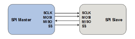
- SCK (Serial Clock): SCK is a serial clock line, the role of Master Slave transmission clock signal to control the timing and rate of data exchange
- MOSI (Master Out Slave in): In the SPI Master also called Tx-channel, SPI master role to a slave SPI data transmission
- CS / SS (Chip Select / Slave Select): Select Slave SPI Master role which communicate with a SPI, low level indicates slave is selected (active low)
- MISO (Master In Slave Out): in the SPI Master also called Rx-channel, SPI master role receives data over the SPI slave transmission
SPI bus has the following characteristics:
1, a master-slave mode, the communication between two predetermined SPI SPI Slave devices must control the device by the master device from the Master. Master may be provided while a plurality of chip select (Chip Select) to control a plurality Slave. Slave SPI protocol also provides device provided by a clock by Master Slave SCK pin to, or are unable to generate control Slave clock, the clock is no Slave does not work properly.
Multi Single Master Slave typical structure shown below:

2, SPI bus while transmitting data is also transmitted clock signal, the SPI protocol is a synchronous transmission protocol (Synchronous). Master clock pulse is generated corresponding to the data to be exchanged, the composition of the clock signal, a clock signal through a clock polarity (the CPOL) and clock phase (CPHA) when controlling two SPI devices exchange data and when the received data is sampled, ensure data synchronization between the two devices is a transmission
3, SPI bus is a serial communication protocol of a full-duplex protocol, the previous high data transmission, low in the post. SPI SPI protocol specifies a device not only acts as a sender (Transmitter) in the data communications or the recipient (Receiver). In the case where the chip select signal CS is 0, each clock cycle, SPI device will send and receive 1 bit of data, the equivalent of 1 bit data to be exchanged. Data transfer is MSB after (MSB first)
SPI master schematic view of the structure shown in the following internal data transfer from the 
mode of the SPI bus transfer:
SPI bus a total of four transmission modes, which are four modes by the clock polarity (CPOL, Clock Polarity) and clock phase (CPHA, Clock Phase ) is defined, wherein the predetermined level of the parameter CPOL clock signal SCK idle state, the CPHA predetermined data is sampled on the rising edge or falling edge of the SCK clock is sampled.
-
Mode 0: CPOL = 0, CPHA = 0. Serial clock line SCK is low when idle, data is sampled on the rising edge of the clock SCK, SCK falling edge of the data clock of the switching
-
Mode 1: CPOL = 0, CPHA = 1. Serial clock line SCK is low when idle, the data is sampled on the falling clock SCK, the data is switched on the rising edge of the clock SCK
-
Mode 2: CPOL = 1, CPHA = 0. Serial clock line SCK is high when idle, the data is sampled on the falling clock SCK, the data is switched on the rising edge of the clock SCK
-
模式3:CPOL= 1,CPHA=1。SCK串行时钟线空闲是为高电平,数据在SCK时钟的上升沿被采样,数据在SCK时钟的下降沿切换
时钟相位、极性有四种组合方式,时钟相位、极性的选择决定了传输是否以第一个发送时钟作为开始,停止时时钟是否保持为高电平等问题。

基本的SPI协议也称为Single-SPI,需要至少4根线(支持全双工)或者3根线(支持半双工)
而在single-SPI 协议基础上,扩展出Dual-SPI 和 Quad-SPI协议:
Dual-SPI协议:
- 在Dual-SPI协议中,MOSI、MISO数据线被重名为SD0、SD1,即可以做输出,也可以输入双向信号线
- Dual-SPI 协议同时使用两根数据线进行传输,在一段时间或者全部做输出(发送数据),或者全部做输入(接受数据),因此是半双工的方式。
- 由于同时使用两根数据线进行传输,一个周期可以传送2bit的信号,因此在单向传输时,数据的吞吐率能够提高一倍。
Quad-SPI协议:
- Quad-SPI在Dual-SPI的基础上再添加2根数据线,使得数据线变成4根,分别为SD0、SD1、SD2和SD3
- Quad-SPI同样使用半双工的方式,一周期可以传递4bit信号。
其中的发送、接受FIFO
若发送、接受FIFO深度为8,宽度为16,与串行传输的位数在4到16bit之间,当传输数据不满16bit,需要右对齐;即保证每个FIFO的单元只存在一个串行传输的数据(复位时,发送、接受FIFO清空,会产生写满中断以及读空中断)
模式选择由TMOD寄存器决定,传输模式不影响串行传输的双工行:
- 同时发送和接受,发送数据从发送FIFO弹出,通过TXD给目标器件,从目标器件接受的数据移入移位寄存器,在每帧数据结束进入接受FIFO
- 只发送,只是接受移位寄存器接受的数据不进入接受FIFO,下次传输被覆盖
- Only accept, accept only mode does not work
