Article directory
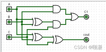
1. One-bit full adder
(1) Logical expression:
cout = A ⊕ B ⊕ C;
C1 = AB +(A⊕B)C
(2) The circuit diagram is as follows:
提示:以下是本篇文章正文内容,下面案例可供参考
Two, four-bit parallel adder
(1) Logical expression:
C1=G0+P0C0
C2=G1+P1C1=G1+P1G0+P1P0G0
C3=G2+P2C2=G2+P2G1+P2P1G0+P2P1P0C0
C4=G3+P3C3=G3+P3G2+P3P2G1+P3P2P1G0+ P3P2P1P0C0
(2) The circuit diagram is shown in the figure:

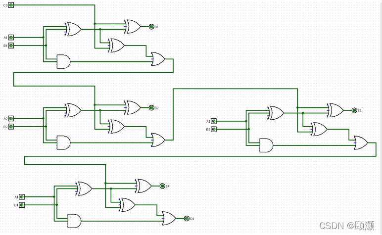
Three, four bit serial adder:
(1) Logical expression:
C1=A1B1+(A1⊕B1)C0
C2=A2B2+(A2⊕B2)C1
C3=A3B3+(A3⊕B3)C2
C4=A4B4+(A4⊕B4)C3
(2) The circuit diagram is shown in the figure Show: