先简单介绍一下ILA(Integrated Logic Analyzer)生成方法。这里有两种办法完成Debug Core的配置和实现。
方法一、mark_debug综合选项+Set Up Debug设定ILA参数。
1、在信号(reg或者wire)声明处加mark_debug选项,方法如下:
// spi_mosi信号标记为需要ILA观测的信号
(* MARK_DEBUG = “TRUE” *) wire spi_mosi;
mark_debug用法的详细说明请看Xilinx文档UG901_Synthesis
2、综合,进行Run Synthesis
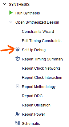
3、Open Synthesized Design,打开Set Up Debug,如图:
4、为ILA Debug Core添加需要观测的信号,结果如图:

每一个信号都要指定一个采样时钟域(Clock Domain)。
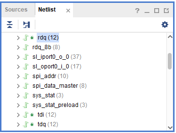
关于添加方法,还可以在Netlist窗口拖动信号到这个列表内。
注意到Netlist中有些信号名称前面有了绿色的小蜘蛛(小星星) ,正是Verilog程序中进行mark_debug的信号:
5、在Set Up Debug中设定信号采样收集的深度(Sample of data depth),输入流水级别数(Input pipe stages),Capture control和Advanced trigger选项。
6、完成ILA配置,保存Debug Setup,Run Implementation
说明:
完成了Debug Setup以后重新进行Implementation,XDC文件中被附加上了配置debug Core的XDC语句,例如:
# 下面这句创建一个新的调试核,名称u_ila_0
create_debug_core u_ila_0 ila
set_property ALL_PROBE_SAME_MU true [get_debug_cores u_ila_0]
set_property ALL_PROBE_SAME_MU_CNT 4 [get_debug_cores u_ila_0]
set_property C_ADV_TRIGGER true [get_debug_cores u_ila_0]
set_property C_DATA_DEPTH 8192 [get_debug_cores u_ila_0]
set_property C_EN_STRG_QUAL true [get_debug_cores u_ila_0] set_property C_INPUT_PIPE_STAGES 3 [get_debug_cores u_ila_0] set_property C_TRIGIN_EN false [get_debug_cores u_ila_0] set_property C_TRIGOUT_EN false [get_debug_cores u_ila_0] # 下面这句为u_ila_0调试核设定端口clk的宽度为1 set_property port_width 1 [get_debug_ports u_ila_0/clk] # 下面这句为u_ila_0调试核设定采样时钟信号(clk)为sys_sam_clk connect_debug_port u_ila_0/clk [get_nets [list sys_pll_01/inst/sys_sam_clk]] set_property PROBE_TYPE DATA_AND_TRIGGER [get_debug_ports u_ila_0/probe0] set_property port_width 21 [get_debug_ports u_ila_0/probe0] # 下面这句为u_ila_0调试核连接待观测信号corr_i_quant connect_debug_port u_ila_0/probe0 [get_nets [list {corr_i_quant[0]} {corr_i_quant[1]} {corr_i_quant[2]} {corr_i_quant[3]} {corr_i_quant[4]} {corr_i_quant[5]} {corr_i_quant[6]} {corr_i_quant[7]} {corr_i_quant[8]} {corr_i_quant[9]} {corr_i_quant[10]} {corr_i_quant[11]} {corr_i_quant[12]} {corr_i_quant[13]} {corr_i_quant[14]} {corr_i_quant[15]} {corr_i_quant[16]} {corr_i_quant[17]} {corr_i_quant[18]} {corr_i_quant[19]} {corr_i_quant[20]}]] create_debug_port u_ila_0 probe set_property PROBE_TYPE DATA_AND_TRIGGER [get_debug_ports u_ila_0/probe1] set_property port_width 12 [get_debug_ports u_ila_0/probe1] connect_debug_port u_ila_0/probe1 [get_nets [list {rdq[0]} {rdq[1]} {rdq[2]} {rdq[3]} {rdq[4]} {rdq[5]} {rdq[6]} {rdq[7]} {rdq[8]} {rdq[9]} {rdq[10]} {rdq[11]}]] create_debug_port u_ila_0 probe set_property PROBE_TYPE DATA_AND_TRIGGER [get_debug_ports u_ila_0/probe2] set_property port_width 12 [get_debug_ports u_ila_0/probe2] connect_debug_port u_ila_0/probe2 [get_nets [list {rdi[0]} {rdi[1]} {rdi[2]} {rdi[3]} {rdi[4]} {rdi[5]} {rdi[6]} {rdi[7]} {rdi[8]} {rdi[9]} {rdi[10]} {rdi[11]}]] create_debug_port u_ila_0 probe set_property PROBE_TYPE DATA_AND_TRIGGER [get_debug_ports u_ila_0/probe3] set_property port_width 12 [get_debug_ports u_ila_0/probe3] connect_debug_port u_ila_0/probe3 [get_nets [list {tdi[0]} {tdi[1]} {tdi[2]} {tdi[3]} {tdi[4]} {tdi[5]} {tdi[6]} {tdi[7]} {tdi[8]} {tdi[9]} {tdi[10]} {tdi[11]}]] create_debug_port u_ila_0 probe set_property PROBE_TYPE DATA_AND_TRIGGER [get_debug_ports u_ila_0/probe4] set_property port_width 12 [get_debug_ports u_ila_0/probe4] connect_debug_port u_ila_0/probe4 [get_nets [list {tdq[0]} {tdq[1]} {tdq[2]} {tdq[3]} {tdq[4]} {tdq[5]} {tdq[6]} {tdq[7]} {tdq[8]} {tdq[9]} {tdq[10]} {tdq[11]}]] create_debug_port u_ila_0 probe set_property PROBE_TYPE DATA_AND_TRIGGER [get_debug_ports u_ila_0/probe5] set_property port_width 1 [get_debug_ports u_ila_0/probe5] connect_debug_port u_ila_0/probe5 [get_nets [list bb_sam_clk_5]] create_debug_port u_ila_0 probe set_property PROBE_TYPE DATA_AND_TRIGGER [get_debug_ports u_ila_0/probe6] set_property port_width 1 [get_debug_ports u_ila_0/probe6] connect_debug_port u_ila_0/probe6 [get_nets [list AD_SPI_MOSI_OBUF]] create_debug_port u_ila_0 probe set_property PROBE_TYPE DATA_AND_TRIGGER [get_debug_ports u_ila_0/probe7] set_property port_width 1 [get_debug_ports u_ila_0/probe7] connect_debug_port u_ila_0/probe7 [get_nets [list AD_SPI_CLK_OBUF]] create_debug_port u_ila_0 probe set_property PROBE_TYPE DATA_AND_TRIGGER [get_debug_ports u_ila_0/probe8] set_property port_width 1 [get_debug_ports u_ila_0/probe8] connect_debug_port u_ila_0/probe8 [get_nets [list AD_SPI_EN_B_OBUF]] create_debug_port u_ila_0 probe set_property PROBE_TYPE DATA_AND_TRIGGER [get_debug_ports u_ila_0/probe9] set_property port_width 1 [get_debug_ports u_ila_0/probe9] connect_debug_port u_ila_0/probe9 [get_nets [list AD_SPI_MISO_IBUF]] set_property C_CLK_INPUT_FREQ_HZ 300000000 [get_debug_cores dbg_hub] set_property C_ENABLE_CLK_DIVIDER false [get_debug_cores dbg_hub] set_property C_USER_SCAN_CHAIN 1 [get_debug_cores dbg_hub] connect_debug_port dbg_hub/clk [get_nets sys_ref_clk_BUFG]
方法二、HDL文件中例化ILA IP Core。
在IP Catalog中添加ILA核,基本的参数有:需要观测的信号个数(Number of Probes),采集深度(Sample data depth)和各个信号探头(Probe)的位宽。
调试时需要在Debug Probes 里面增加信号到波形窗口中!