最近在研究体素渲染技术,网上找了一些资料不是很如意,无意中找到了一篇老外写的文章,把英文也贴出来,读者可以自行翻译,通过这篇文章让读者至少了解可以用体素做哪些事情?看看如何将其应用到项目开发中。
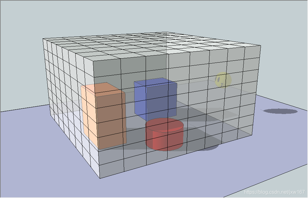
A voxel representation of a scene has spatial data as opposed to the conventional rasterization view (as stored in a render target) which just has a slice of depth value. A voxelized scene can be easily traversed spatially and you can access data from coarse world locations. This enables rendering techniques which require spatial data such as indirect illumination, more convincing ambient occlusion and volumetric light shafts. Also it is also possible to utilize voxel information to make gameplay decisions. An example would be to cast a ray in the voxel grid to check a visibility. If you have ideas which could make use of coarse spatially organized information from your scene, voxel representation is worth considering.
一个场景的体素可以用3D空间数据表示,而不是传统的栅格化视图(存储在渲染目标中),后者只有一个深度值,可以很容易地在空间上遍历一个体素场景,并且可以访问场景中的数据。例如光照、更有说服力的环境遮挡和体积光,也可以利用体素信息来做游戏场景处理方案。例如,在体素网格中投射光线以检查其可见性,如果你有其他想法可以利用你的场景体素来组织场景等等,这些都可以用体素来表示。
The basic concept of GPU Voxelization to use GPU shaders to convert a scene composed of triangle meshes into a regular voxel grid representation.
The process for doing this is pretty straightforward.
First you transform the vertex positions of a primitive into a regular eulerian grid (the “voxel grid”) coordinate system in the Vertex Shader stage.
Then you rasterize the transformed primitive using a viewport of the same dimensions as one of the 2D projections of the voxel grid. Because the orthogonal viewport frustum can cover the voxel grid exactly, and a rasterized pixel position in the render target and its depth value correspond X, Y and Z components of the voxel grid.
Then, finally, map each rasterized fragment onto one or several voxels and write some data into those voxels in the Pixel Shader stage. Note that the data is written to a 3D texture which is bound as a UAV buffer, not a 2D conventional render target. You don’t need a render target at all, but you need to set a proper viewport that is aligned with a face of the voxel grid.
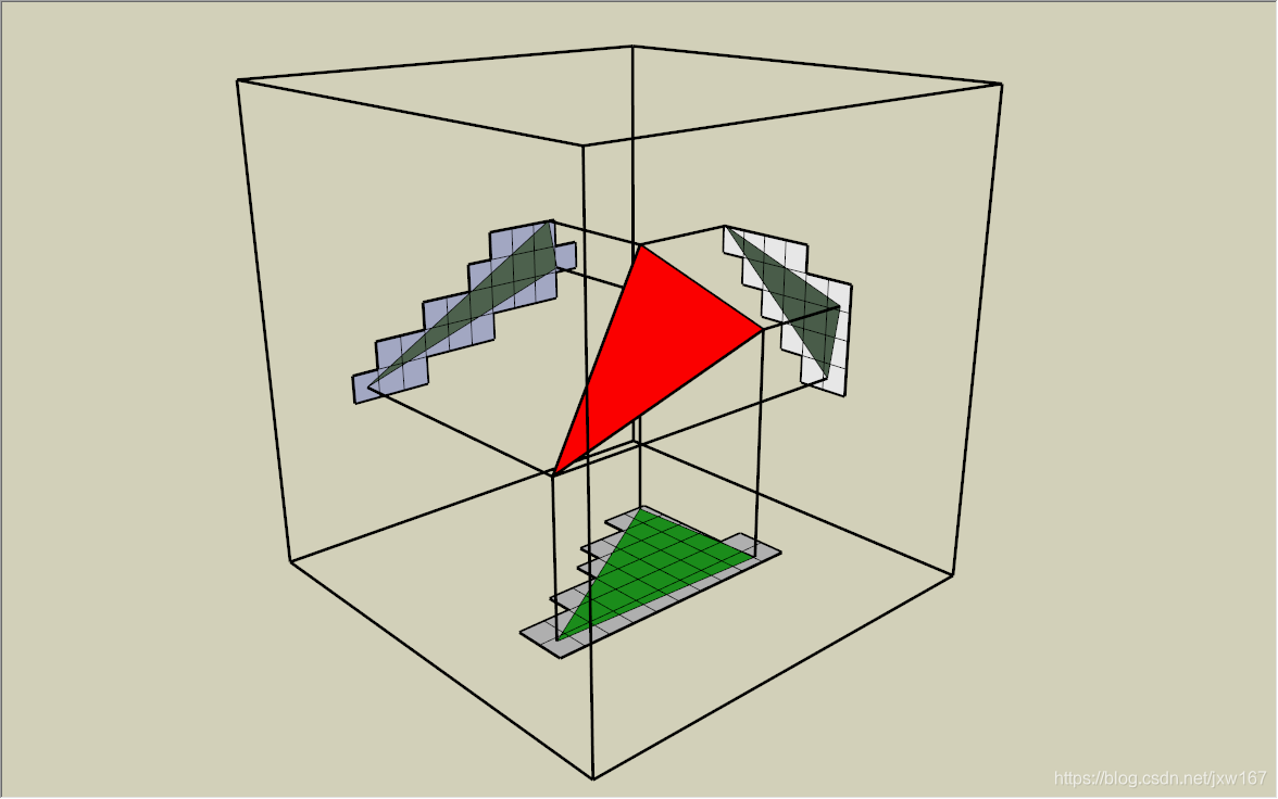
The following pictures describe this process visually.
GPU体素化的基本概念是使用GPU着色器将一个由三角形网格组成的场景转换成一个规则的体素网格表示,这个过程非常简单。
首先,在顶点着色器阶段,将物体的顶点位置转换为常规的欧拉网格(“体素网格”)坐标系统,读者可以自行研究一下体素网格是什么网格?
然后,使用与体素网格在2D投影中的一个相同维度的视点来对转换后的图元进行光栅化。由于正交视锥体可以精确覆盖体素网格,且光栅化后的像素在渲染目标中的位置与其深度值对应体素网格的X、Y、Z分量。最后,将每个光栅化的片段映射到一个或几个体素上,并将一些数据写入像素着色器阶段的体素中。注意,数据被写入到一个3D纹理,绑定为UAV缓冲区,而不是2D常规渲染目标。我们根本不需要渲染目标,但是需要设置一个与体素网格的面对齐的适当的视口,下面的图片直观地描述了这个过程。
正交摄像机下的体素网格表示
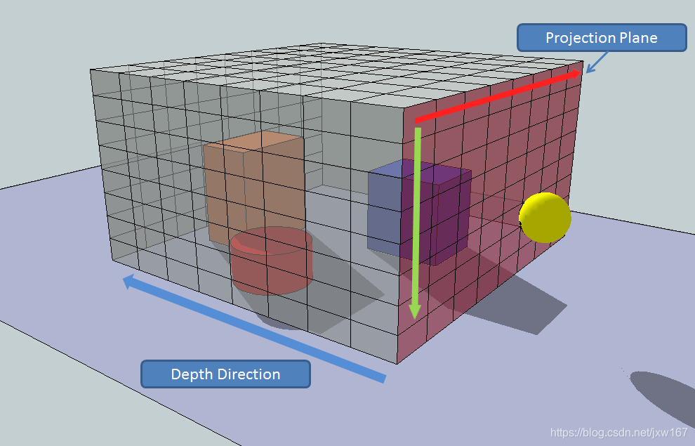
渲染目标上的像素位置和深度值对应的X, Y, Z的立体像素网格
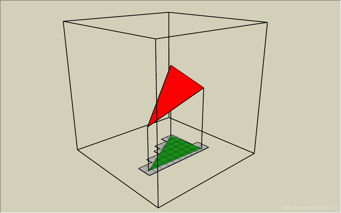
However you voxelize continuous primitive planes, there are cases that fail to voxelize correctly and have holes or slits in the result. The following two pictures are the results of voxelizations which were done with identical primitives and voxel grid.
The one which was done with horizontal camera direction got correct-looking results and the primitive was sufficiently voxelized. However, the other was done with vertical camera direction and is not sufficiently voxelized, having cracks between voxels. This is because the shader runs based on pixels covered in the viewport. Thus, if the slope of the primitive being drawn is steep with respect to the view direction, you can get cracks.
无论如何对连续的原始平面进行体素化,都有一些情况不能正确地进行体素化,结果会出现孔洞或裂缝。下面两幅图是用相同的原理和体素网格进行体素化的结果。从水平摄像机方向进行的实验得到了正确的结果,并对物体进行了充分的体素化处理。然而,另一种方法是从垂直摄像机方向,没有充分地进行体素化,在体素之间存在裂纹。这是因为着色器是基于视图中覆盖的像素运行。因此,如果要绘制的物体斜率相对于视图方向是陡峭的,就会出现裂缝。
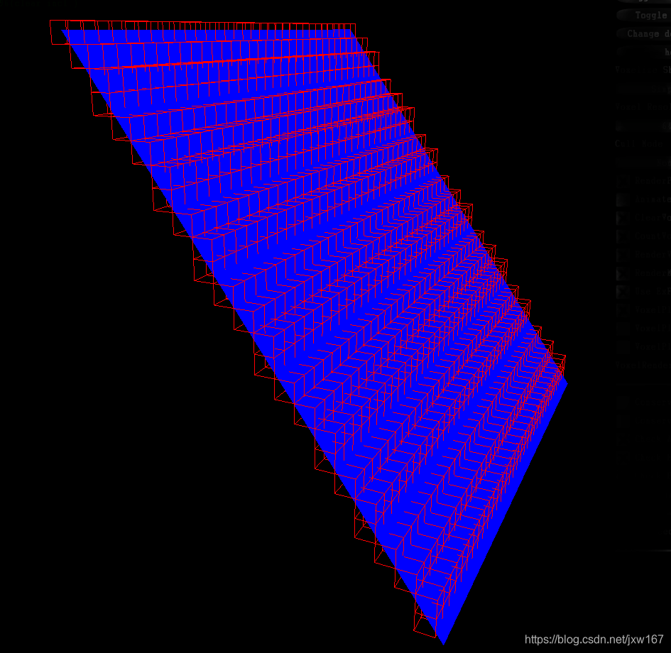
从右向左的体素相机处理
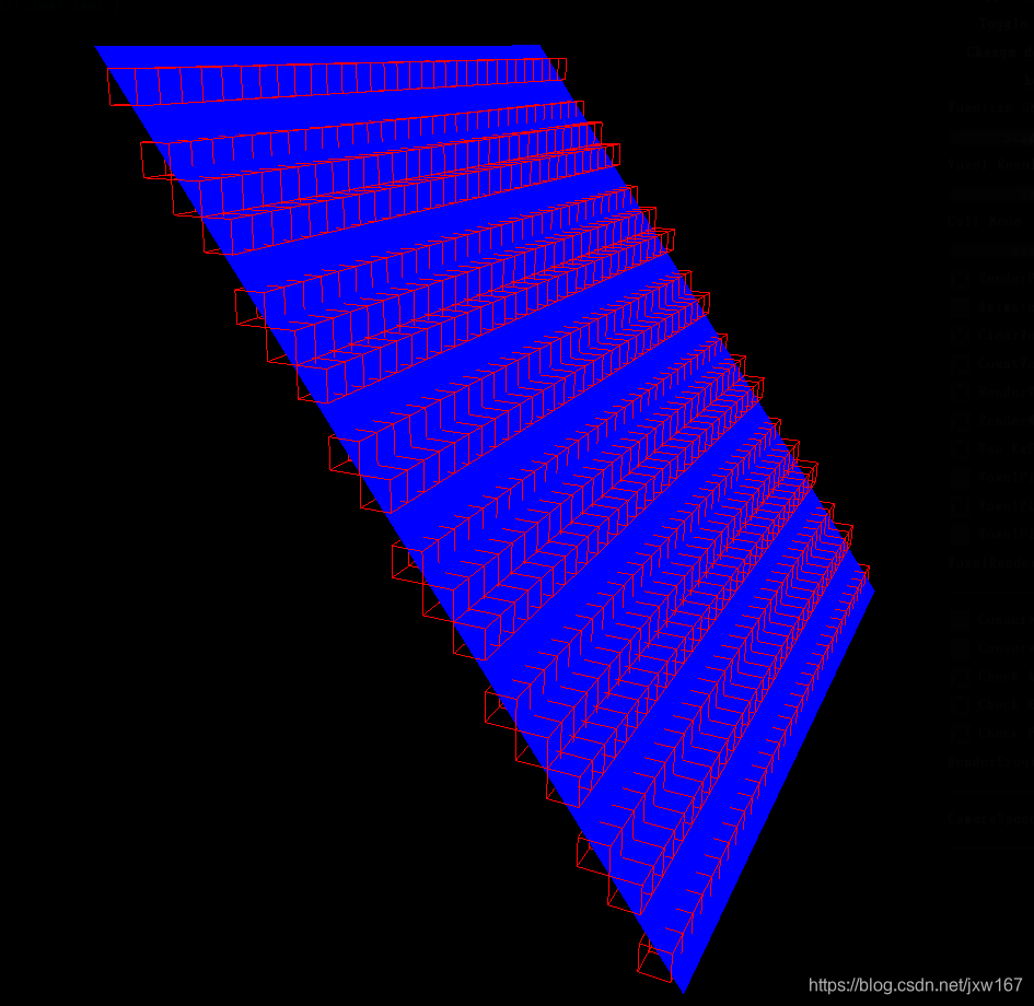
从上向下对物体的体素化处理
More specifically, whether or not you’ll get cracks depends on the depth gradient of the primitive being rendered. This can be calculated with ddx(depth), ddy(depth) in the pixel shader. If either of these gradients exceeds 1.0, then the voxelized plane will have “cracks” in a direction perpendicular to the depth direction.
更具体地说,你是否会得到裂缝取决于被渲染的深度梯度,这可以用ddx(深度),ddy(深度)在像素着色器中计算。如果这两个梯度都超过1.0,那么体化平面将在垂直于深度方向的方向上出现“裂缝”。
To fix this issue, primitives need to be rendered from an axis that presents the largest face area with respect to the camera. In other words, from a camera direction selected from the X, Y and Z axes according to the face normal. Since the different faces of a single mesh are all differently oriented, this requires rendering the mesh from potentially 3 different directions; but we don’t need 3 render passes. Since the X, Y and Z axes are orthogonal each other, we just need to swizzle the X, Y and Z components to change the projection direction, and this can be done in the geometry shader stage per primitive. Then, the pixel shader restores the coordinate components according to the information that comes from the GS. In that fashion we can avoid the issue of missing voxels caused by high depth gradients.
为了解决这个问题,需要从一个轴上呈现相对于相机最大的面区域。换句话说,从一个相机的方向根据面法线选择X, Y和Z轴。由于单个网格的不同面都有不同的方向,这就需要从3个不同的方向来呈现网格;但是我们不需要3个渲染通道,由于X, Y和Z轴是正交的,我们只需要旋转X, Y和Z分量来改变投影方向,这可以在几何着色器阶段完成。然后,像素着色器根据来自GS的信息恢复坐标分量。通过这种方式,我们可以避免高深度梯度造成的体素缺失问题。
从三个方向对其投射
Selecting the proper projection direction has fixed “cracks”. However, by breaking up the projection directions we can introduce a new problem of “holes”. The following picture will describe it in 2D. Please think these three different colored line segments as three adjoining primitives on a single mesh.
选择合适的投影方向可以固定“裂缝”,然而,通过分解投影方向,我们可以引入一个新的“洞”问题。下面的图片将用2D来描述它,请将这三个不同颜色的线段看作是一个网格上的三个相邻基元。
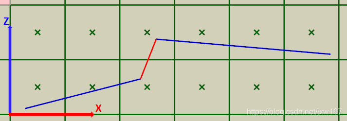
蓝色投影在Z上,红色投影在X上
In order to project the largest area, we’ve chosen the projection plane in the GS. Blue colored segments are projected in the Z axis direction and the red segment is projected in the X axis direction. This results in the following pixel shader invocations.
为了投影出最大的面积,我们选择了GS中的投影平面。蓝色的线段投影在Z轴方向,红色的线段投影在X轴方向,这将导致以下像素着色器调用。
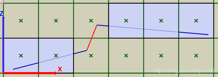
像素上的蓝色阴影表示“覆盖”像素。注意像素是不被覆盖的空白。
Generally, a pixel shader is invoked when a primitive covers the center of a pixel. When the red segment is projected in the X direction, none of the pixel centers were covered, so it wasn’t rasterized at all. This issue wouldn’t happen if all of the primitives were projected in a single direction. Changing the projection direction causes this issue. To fix this issue, we need to change the rasterization rules to consider a pixel covered if any part of it is touched by a primitive. This type of rasterization is called Conservative Rasterization. There is a great article covering how to perform this manually (by expanding primitive edges) in GPU Gems 3: [GPU Gems: Chapter 42 Conservative Rasterization]. As a quick summary, the technique expands primitive edges to ensure all pixels touched are covered. We’ll also talk about a possibly better alternative at the end of this blog post.
通常,当覆盖像素的中心时,将调用像素着色器。当红色线段在X方向上投影时,没有一个像素中心被覆盖,所以根本没有光栅化。如果所有的物体都投射到一个方向上,那么这个问题就不会发生。改变投影方向会导致这个问题,为了解决这个问题,我们需要更改光栅化规则,以便在像素的任何部分被触摸时考虑覆盖的像素。这种类型的光栅化称为Conservative 光栅化。在GPU Gems 3: [https://developer.nvidia.com/gpugems/GPUGems2/gpugems2_chapter42.html]中有一篇很棒的文章介绍了如何手动执行这一操作(通过扩展原始边缘)。该技术扩展了原始边缘,以确保所有被触摸的像素都被覆盖,我们也会在这篇博文的结尾讨论一个更好的选择。
Also, finally, should note that if you are running the new Maxwell base chip set (or higher) you can make use of actual official artifact-free conservative raster by using NVAPI. Here’s the link. [Don’t be conservative with Conservative Rasterization] If you use the hardware conservative raster supported by Maxwell GPUs, then you need not worry about the artifacts from expanding primitive edges, and a lot of the following sections can be ignored (as they are covering how to deal with edge extension artifacts!).
最后,还要注意,如果正在运行新的Maxwell基芯片集(或更高版本),那么可以使用NVAPI来使用实际的无手动创建的Conservative 光栅。https://developer.nvidia.com/content/dont-be-conservative-conservative-rasterization
如果使用Maxwell gpu支持的硬件Conservative 光栅,那么就不必担心扩展原始边缘所带来的问题,并且可以忽略以下许多部分(因为它们涉及了如何处理边缘扩展工件!)
Finally, we’ve got a sufficiently complete voxelization. However, there is still an issue we have left. If you used the technique of expanding the primitive’s edges in GS to get us Conservative Rasterization, some extra pixels are shaded. Yellow pixels in the following picture are the extra pixels not covered by the primitive, but still shaded. Especially for thin triangles, this method will produce a fair number of extra pixel shader calls.
最后,我们得到了一个足够完整的体素化,然而,还有一个问题我们没有解决,如果使用在GS中展开边缘的技术来得到Conservative 的光栅化,一些额外的像素将被着色。下图中的黄色像素是未被覆盖的额外像素,但仍然有阴影,特别是对于细三角形,这种方法将产生相当数量的额外像素着色器调用。
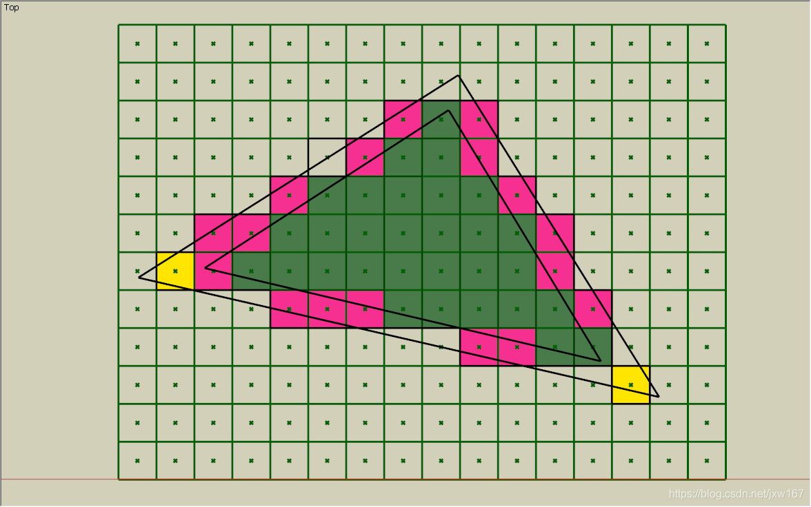
绿色是初始覆盖像素,红色是被保守光栅覆盖的期望像素,黄色被错误地覆盖了。
The following picture illustrates a primitive (red plane) intersecting multiple voxels in the depth direction, which means in the same pixel.
下图显示了在深度方向上相交于多个体素物体(红色平面),这意味着它们在同一个像素上。
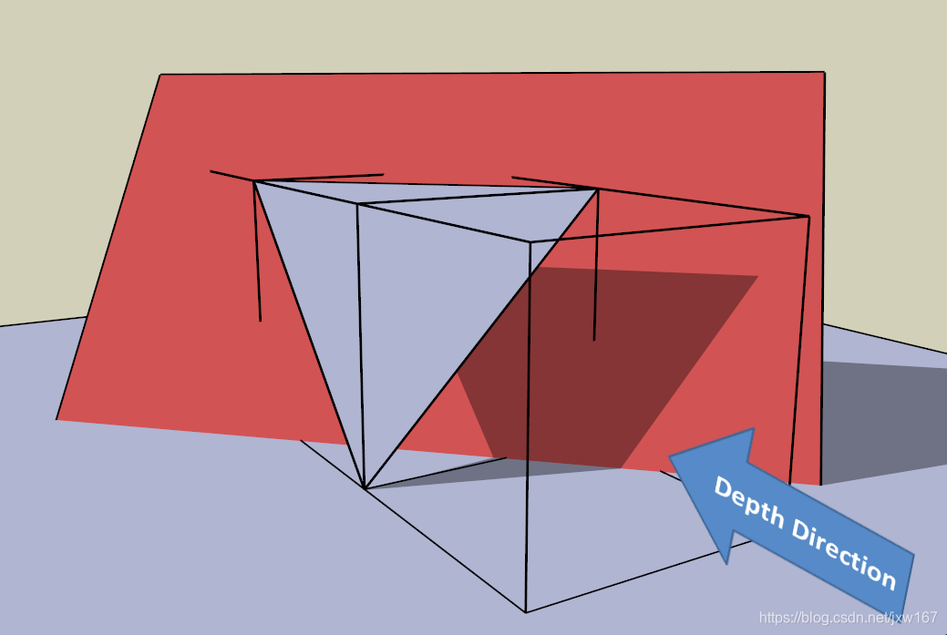
红色平面在深度方向上与3个体素相交。
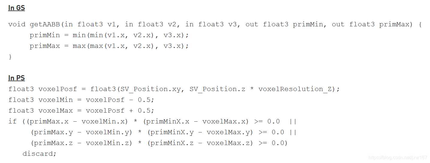
The light purple triangle’s ddx(depth) and ddy(depth) are indeed just 1.0, and the red plane is parallel to it. These planes have the maximum depth gradient possible in the process of voxelization. The red plane intersects front, center and rear voxels. Since these are in the same pixel, the Pixel Shader will be invoked once for all of them. If we apply the conservative rule in the depth direction, we must check for intersections between the primitive’s plane and these 3 voxels in the Pixel Shader. To do that, we can calculate the depth gradient in the Geometry Shader and pass it to the Pixel Shader, or compute the depth gradient in the Pixel Shader with the ddx and ddy functions. Then, we check for intersections between the primitive’s plane and these 3 voxels, using the gradient value and the depth value at the center of the pixel (which should be retrieved as a pixel’s depth value in the Pixel Shader).When you intersect a voxel with a primitive, you think of the voxel as being a certain shape, such as a box or sphere. This shape, called the intersection target, will determine topological conditions of the voxelized primitive. If you’re interested in intersection targets, you should refer to A Topological Approach to Voxelization [Samuli Laine, 2013]. In this section, we use the entire box of a voxel as an intersection target. To check intersection between a voxel and a primitive, there are some generic intersection tests, such as the Separating Axis Theorem; we will use a method that can separate its workload between the GS and PS. The process consists of two parts. The first one is an AABB (Axis Aligned Bounding Box) test and the second one is an edge-voxel condition test. If a voxel passes these two tests then the primitive intersects that voxel and the voxel is covered.
浅紫色三角形的ddx(深度)和ddy(深度)实际上只有1.0,红色平面与之平行,这些平面在体素化过程中具有最大的深度梯度。红色平面与前、中和后体素相交。因为它们都在同一个像素中,因此所有像素着色器都会被调用一次。如果我们在深度方向上应用规则,我们必须检查基面的平面和像素着色器中的这3个体素之间的交点,为此,我们可以计算几何着色器中的深度梯度并将其传递给像素着色器,或者使用ddx和ddy函数计算像素着色器中的深度梯度。然后,我们使用渐变值和像素中心的深度值(应该作为像素着色器中的像素深度值检索)来检查平面和这3个体素之间的交集。当你将一个体素与一个基面相交时,你认为体素是一个特定的形状,例如一个盒子或球体。这种形状称为相交目标,它将确定被体化的拓扑条件,如果对交集目标感兴趣,应该参考体素化的拓扑方法[Samuli Laine, 2013]。在本节中,我们使用体素的整个框作为交集目标。为了检查体素和基础物体之间的交集,有一些通用的交集测试,比如分离轴定理;我们将使用一种方法在GS和PS之间分离它的工作负载。第一个是AABB(轴向对齐边界框)测试,第二个是边体素条件测试。如果一个体素通过这两个测试,那么原始物体就会与该体素相交,从而覆盖该体素。

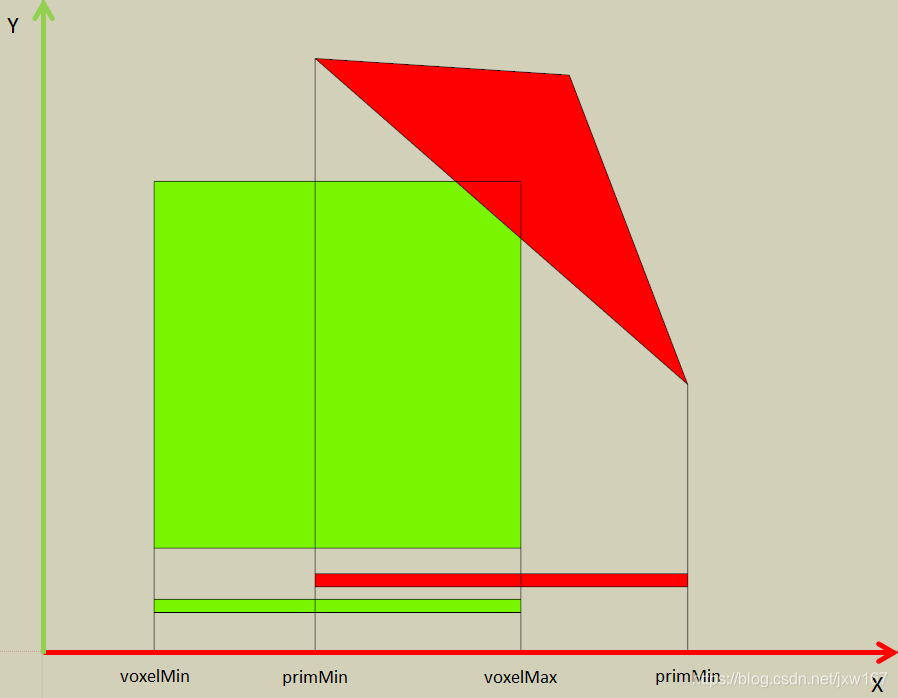
The voxel’s AABB is defined by the regular voxel grid. The primitive’s AABB can be found from the maximum and minimum X, Y and Z of its vertex coordinates. To achieve better workload balancing, a primitive’s AABB should be calculated in the GS, then the voxel-primitive AABB test should be done in the PS. The test is passed if the voxel bounding box intersects the primitive’s AABB.
体素的AABB是由普通体素网格定义的。原始物体的AABB可以从其顶点坐标的最大值和最小值X、Y和Z中找到。为了更好的平衡工作负载,在GS中计算原始物体的AABB,在PS中进行体素-原始物体的AABB测试。如果体素包围盒与原始物体的AABB相交,测试通过。
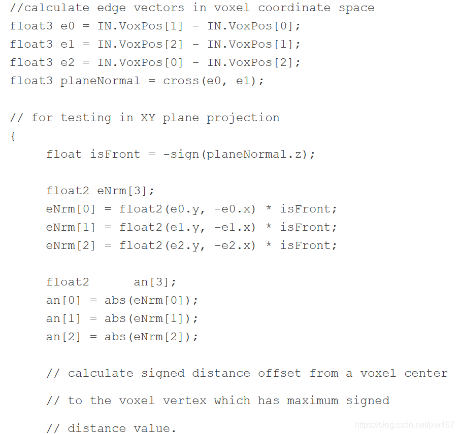
The following pseudocode illustrates this process.
下面的伪代码演示了这个过程。
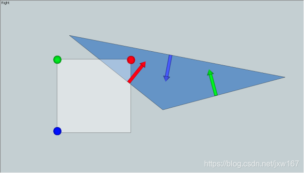
Checking the edge-voxel condition is done in in each of the three axis-aligned planes. For each edge, we calculate the signed distance from the edge to the voxel’s vertices. The maximum signed distance value across all the voxel’s vertices is used for the test. In the following picture, the edge with the red normal vector is checked with the vertex colored red, which is the voxel corner with the maximum signed distance along the red normal. The other two edges (green and blue) are checked similarly. If all of the calculated signed distances are positive, this test is passed.
在三个轴向平面中的每一个都要检查边缘体素条件,对于每条边,我们计算从边到体素顶点的带符号距离。测试使用所有体素顶点的最大有符号距离值。在下面的图中,用红色法向量的边与红色的顶点进行检查,红色的顶点是体素角,它是沿着红色法向量的最大带符号距离。另外两条边(绿色和蓝色)也进行了类似的检查。如果所有计算的符号距离都是正数,则通过此测试。
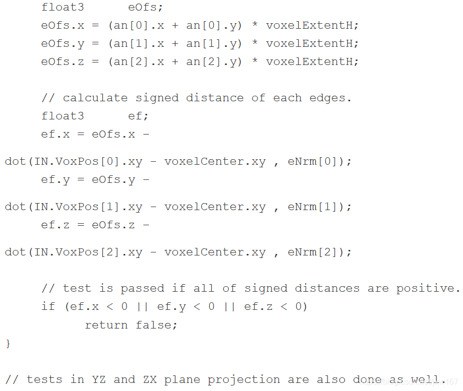
The following code snippet shows the edge-voxel condition tests in the pixel shader.
下面的代码片段显示了像素着色器中的边-体素条件测试。
As we described above, to manually implement conservative rasterization on the GPU, we extended the edges of primitives in the Geometry Shader, which consumes many GPU cycles. In this section, we describe another GPU voxelization approach using MSAA, which does not require expansion of the primitive to get conservative rasterization.
如前所述,为了在GPU上手动实现conservative 光栅化,我们扩展了几何着色器中原始物体的边缘,这将消耗许多GPU。在本节中,我们描述了另一种使用MSAA的GPU体素化方法,它不需要扩展原始物体就可以得到conservative 的光栅化。
Without MSAA, the pixel shader is only invoked for pixels whose centers are covered by a primitive, as we previously discussed.
However, when enabling 8xMSAA, the pixel shader is invoked if any of the subsamples are covered by a primitive. This subsample region covers most of the pixel in 8xMSAA. Additionally, the pixel shader is invoked only once, regardless how many subsamples are covered in a pixel. This is really close to actual conservative rasterization, as long as you have sufficient count and spacing of subsample points. So by using MSAA we don’t need to expand the primitive’s edges, there are no extra pixel shader calls, and the geometry shader is much simpler! This also enables us to skip those primitive-voxel intersection tests which we needed to do to remove the extra voxels!
However, this method is not genuine conservative rasterization. Primitives which lie in-between subsamples still have a possibility not to be voxelized properly. Additionally, you need to create an MSAA render target to bind, which slightly increases the memory cost in vidmem (probably not that big of a deal). If you can utilize Forced Sample Count in DX11.1, you can enable MSAA rasterization without binding an MSAA render target.
So this is a relatively aggressive method, as it has a possibility to have “holes”, which are avoidable by making sure the voxel grid is fine/high-res enough for the sizes of voxelized primitives.
The following three pictures are examples of pixel shader invocations in different rasterization methods.
在没有MSAA的情况下,像素着色器只对中心被原始物体覆盖的像素调用,就像我们前面讨论的那样。但是,在启用8xMSAA时,如果任何子样本被基元覆盖,就会调用像素着色器。这个子样例区域覆盖了8xMSAA中的大部分像素。此外,像素着色器只被调用一次,不管像素中包含多少个子样本。这非常接近实际的conservative 光栅化,只要你有足够的子样本点的计数和间距。因此,通过使用MSAA,我们不需要扩展原始物体的边缘,没有额外的像素着色器调用,而且几何着色器更简单!这也使我们能够跳过那些原始体素交叉测试,我们需要做这些测试来删除额外的体素!然而,这种方法并不是真正的conservative 光栅化。位于子样本之间的原始物体仍然有可能不能正确地进行体素化。另外,您需要创建一个MSAA呈现目标来绑定,这将略微增加vidmem中的内存开销(可能不是很大)。如果可以在DX11.1中使用强制样本计数,则可以启用MSAA栅格化,而无需绑定MSAA呈现目标。因此,这是一种相对激进的方法,因为它可能有“洞”,这是可以避免的,确保体素网格是精细的/高分辨率,足以满足体素化原始物体的大小。下面三幅图是不同栅格化方法中像素着色器调用的例子。
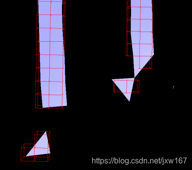
传统光栅化
通过边缘扩展的光栅化
通过MSAArender目标的光栅化
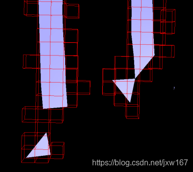
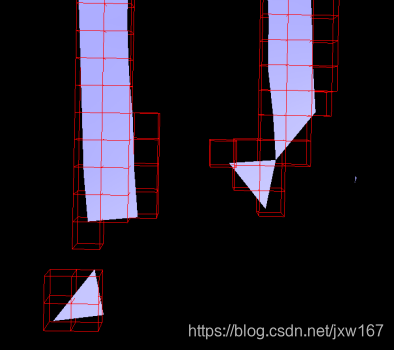
The following three pictures are also examples of voxelizations without voxel-primitive intersection tests.
下面的三张图片也是没有进行体素-原始物体交叉测试的体素分离的例子。

由高梯度引起的裂缝。
传统光栅化的裂缝是固定的,但我们可以看到额外的体素。
光栅化与MSAA渲染目标,没有孔或多余的体素
总结:
In this article, we have described the basics of GPU voxelization. You can choose methods as you like to fit your purpose. Currently, MSAA voxelization is reasonable in most cases, but you might need to implement an accurate method as a reference. Also, if you are running on Maxwell or higher GPU architecture then you should definitely use the official conservative rasterization functions and you can skip edge extension issues.
在本文中,我们描述了GPU 体素化的基础。您可以选择适合您的方法。目前,MSAA 体素化在大多数情况下是合理的,但是您可能需要实现一个准确的方法作为参考。此外,如果您运行在Maxwell或更高的GPU架构上,那么肯定应该使用官方的光栅化函数,可以跳过边缘扩展问题。
参考:
An Accurate Method for Voxelizing Polygon Meshes[Huang et al. 98]
Fast Parallel Surface and Solid Voxelization on GPUs [Michael et al. 10]
Octree-Based Sparse Voxelization Using the GPU Hardware Rasterizer [Cyril et al. 11]
A Topological Approach to Voxelization [Samuli Laine, 2013]
GPU Gems 2 Chapter 42. Conservative Rasterization