HDLBits: 在线学习 SystemVerilog(二十一)-Problem 143-150(状态机四)

HDLBits 是一组小型电路设计习题集,使用 Verilog/SystemVerilog 硬件描述语言 (HDL) 练习数字硬件设计~
网址如下:
https://hdlbits.01xz.net/
关于HDLBits的Verilog实现可以查看下面专栏:
https://www.zhihu.com/column/c_1131528588117385216
缩略词索引:
SV:SystemVerilog
从今天开始新的一章-时序电路,包括触发器、计数器、移位寄存器、状态机等。
今天主要更新状态机,状态机基本是整个HDL中的核心,合理、高效地使用状态机,是数字电路中的重要技能。
Problem 143-2014_q3c
题目说明
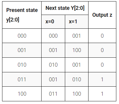
本题和前一题的区别在于,本题的当前状态于端口输入,只需要实现三段式中的状态跳转逻辑以及输出逻辑,不需要实现状态触发器。
模块端口声明
module top_module (
    input clk,
    input [2:0] y,
    input x,
    output Y0,
    output z
);
题目解析
输入端口中的 y 输入当前状态,按照题目要求输出次状态最低位 Y0
module top_module (
    input logic clk,
    input logic [2:0] y,
    input logic x,
    output logic Y0,
    output logic z
);

//define state

parameter logic [2:0]  S0 = 3'b000 , S1 = 3'b001 ,
                       S2 = 3'b010 , S3 = 3'b011 ,
                       S4 = 3'b100 ;

var logic [2:0]  next_state ;

//describe state transition use combinational logic

always_comb begin
    case (y)
        S0: begin
            next_state = x ? S1 : S0 ;
        end

        S1: begin
            next_state = x ? S4 : S1 ;
        end

        S2: begin
            next_state = x ? S1 : S2 ;
        end

        S3: begin
            next_state = x ? S2 : S1 ;
        end

        S4: begin
            next_state = x ? S4 : S3 ;
        end

        default: begin
            next_state = S0 ;
        end
    endcase
end


//describe output decoder use combinational logic

assign z = (y == S3) || (y == S4) ;
assign Y0 = (next_state == S1) || (next_state == S3) ;

endmodule
点击Submit,等待一会就能看到下图结果:
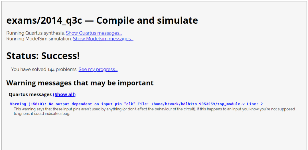
注意图中无波形。
这一题就结束了。
Problem 144-m2014_q6b
题目说明
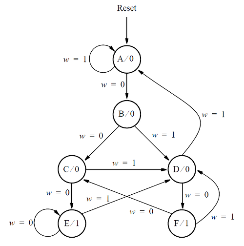
下图为状态机状态转移图。本题需要根据状态转移图以及输入的当前状态 y[3:1]实现状态跳转逻辑,输出次状态的一部分 Y2.

假设希望使用三个触发器和状态代码y[3:1] = 000, 001, ... , 101 分别用于状态 A、B、...、F 来实现 FSM。显示此 FSM 的状态分配表。推导出触发器y[2]的下一状态表达式。
仅实现y[2]的下一状态逻辑。(这更像是一个 FSM 问题,而不是 Verilog 编码问题。哦,好吧。)
模块端口声明
module top_module (
    input [3:1] y,
    input w,
    output Y2);
题目解析
Y2 输出的是对应 Y[2] 的次态,但 Y 在输入时取的是 Y[3:1] ,所以 Y2 取次态 nxt_state[1] 而不是 nxt_state[2]。
module top_module (
    input logic [3:1] y,
    input logic w,
    output logic Y2);


//define state

parameter logic [2:0]  A = 3'b000 , B = 3'b001 ,
                       C = 3'b010 , D = 3'b011 ,
                       E = 3'b100 , F = 3'b101 ;
var logic [2:0] next_state ;

//describe state transition use combinational logic

always_comb begin
    case (y)
        A: begin
            next_state = w ? A : B ;
        end

        B: begin
            next_state = w ? D : C ;
        end

        C: begin
            next_state = w ? D : E ;
        end

        D: begin
            next_state = w ? A : F ;
        end

        E: begin
            next_state = w ? D : E ;
        end

        F: begin
            next_state = w ? D : C ;
        end

        default: begin
            next_state = A ;
        end
    endcase
end

//describe output decoder use combinational logic

assign Y2 = next_state[1] ;

endmodule
点击Submit,等待一会就能看到下图结果:
注意图中无波形。
这一题就结束了。
Problem 145-m2014_q6c
题目说明
本题和前一题的状态转移图相同,但使用独热码来为状态机编码。
模块端口声明
module top_module (
    input [6:1] y,
    input w,
    output Y2,
    output Y4);
题目解析
module top_module (
    input logic [6:1] y,
    input logic w,
    output logic Y2,
    output logic Y4);

    parameter A = 3'd1, B = 3'd2, C = 3'd3,
              D = 3'd4, E = 3'd5, F = 3'd6;

    assign Y2 = ~w & y[A];
    assign Y4 = w & (y[B] | y[C] | y[E] | y[F]);


endmodule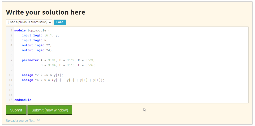
点击Submit,等待一会就能看到下图结果:
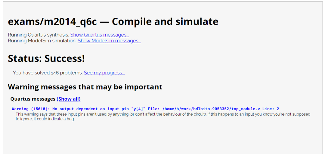
注意图中无波形。
这一题就结束了。
Problem 146-m2014_q6
题目说明
考虑下面显示的状态机,它有一个输入w和一个输出z。
 图片来自HDLBits
实现这个状态机。
模块端口声明
module top_module (
    input clk,
    input reset,     // synchronous reset
    input w,
    output z);
题目解析
module top_module (
    input logic clk,
    input logic reset,  // synchronous reset
    input logic w,
    output logic z);


//define state

typedef enum logic [2:0] { A = 3'b000 , B = 3'b001 ,
                           C = 3'b010 , D = 3'b011 ,
                           E = 3'b100 , F = 3'b101
                         } state_def ;

state_def cur_state , next_state ;

//describe state transition use combinational logic

always_comb begin
    case (cur_state)
        A: begin
            next_state = w ? A : B ;
        end

        B: begin
            next_state = w ? D : C ;
        end

        C: begin
            next_state = w ? D : E ;
        end

        D: begin
            next_state = w ? A : F ;
        end

        E: begin
            next_state = w ? D : E ;
        end

        F: begin
            next_state = w ? D : C ;
        end

        default: begin
            next_state = A ;
        end
    endcase
end


//describe state sequencer use sequential logic

always_ff @( posedge clk ) begin
    if (reset) begin
        cur_state <= A ;
    end
    else begin
        cur_state <= next_state ;
    end
end

//describe output decoder use combinational logic

assign z = (cur_state == E) || (cur_state == F) ;

endmodule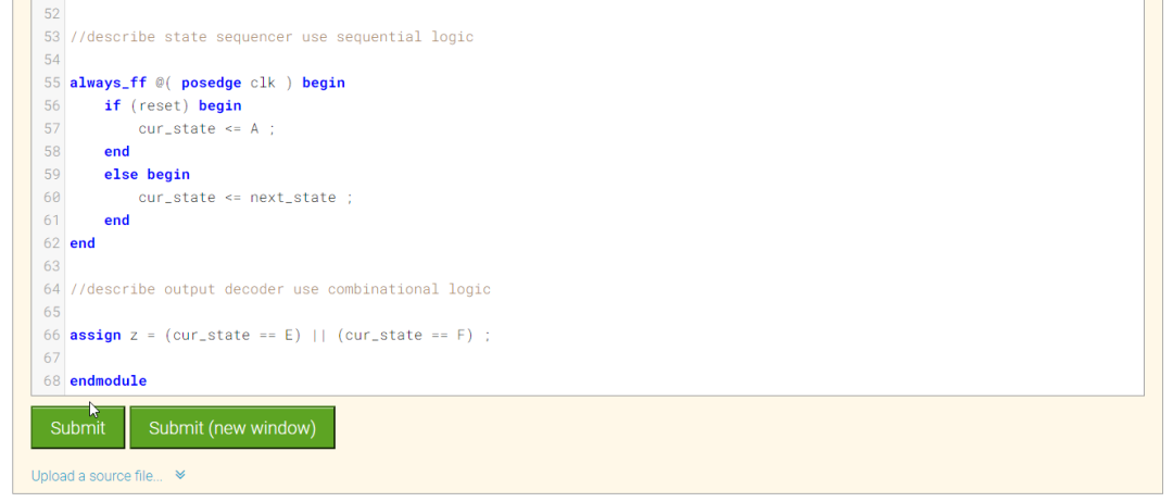
点击Submit,等待一会就能看到下图结果:
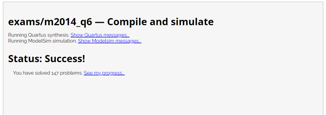
注意图中无波形。
这一题就结束了。
Problem 147-2012_q2fsm
题目说明
考虑下面显示的状态图。

编写代表此 FSM 的完整 Verilog 代码。
模块端口声明
module top_module (
    input clk,
    input reset,   // Synchronous active-high reset
    input w,
    output z
);
题目解析
module top_module (
    input logic clk,
    input logic reset,  // Synchronous active-high reset
    input logic w,
    output logic z);


//define state

typedef enum logic [2:0] { A = 3'b000 , B = 3'b001 ,
                           C = 3'b010 , D = 3'b011 ,
                           E = 3'b100 , F = 3'b101
                         } state_def ;

state_def cur_state , next_state ;

//describe state transition use combinational logic

always_comb begin
    case (cur_state)
        A: begin
            next_state = w ? B : A ;
        end

        B: begin
            next_state = w ? C : D ;
        end

        C: begin
            next_state = w ? E : D ;
        end

        D: begin
            next_state = w ? F : A ;
        end

        E: begin
            next_state = w ? E : D ;
        end

        F: begin
            next_state = w ? C : D ;
        end

        default: begin
            next_state = A ;
        end
    endcase
end


//describe state sequencer use sequential logic

always_ff @( posedge clk ) begin
    if (reset) begin
        cur_state <= A ;
    end
    else begin
        cur_state <= next_state ;
    end
end

//describe output decoder use combinational logic

assign z = (cur_state == E) || (cur_state == F) ;

endmodule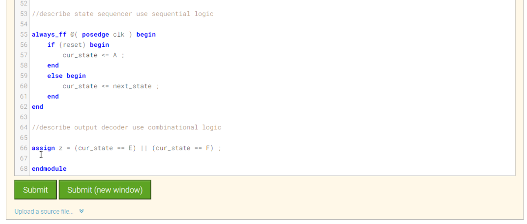
点击Submit,等待一会就能看到下图结果:
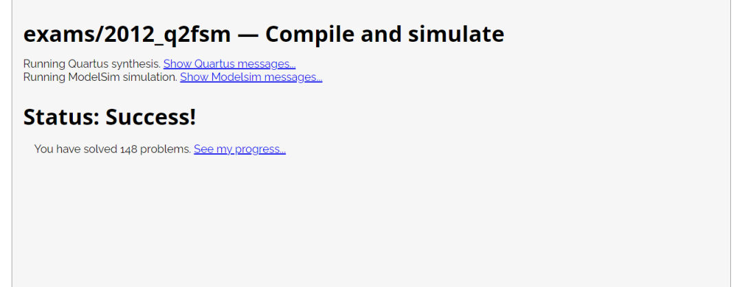
注意图中无参考波形。
这一题就结束了。
Problem 148-2012_q2b
题目说明
本题和此前的题目类似,使用独热码编码方式来描述上题中的状态机。如果在此前的题目中搭建了完善的状态机框架,那么稍稍修改就能够应对此题。
 图片来自HDLBits
模块端口声明
module top_module (
    input [5:0] y,
    input w,
    output Y1,
    output Y3
);
题目解析
module top_module (
    input logic [5:0] y,
    input logic w,
    output logic Y1,
    output logic Y3
);

    parameter A = 3'd0, B = 3'd1, C = 3'd2,
              D = 3'd3, E = 3'd4, F = 3'd5;

    assign Y1 = w & y[A];
    assign Y3 = ~w & (y[B] | y[C] | y[E] | y[F]);

endmodule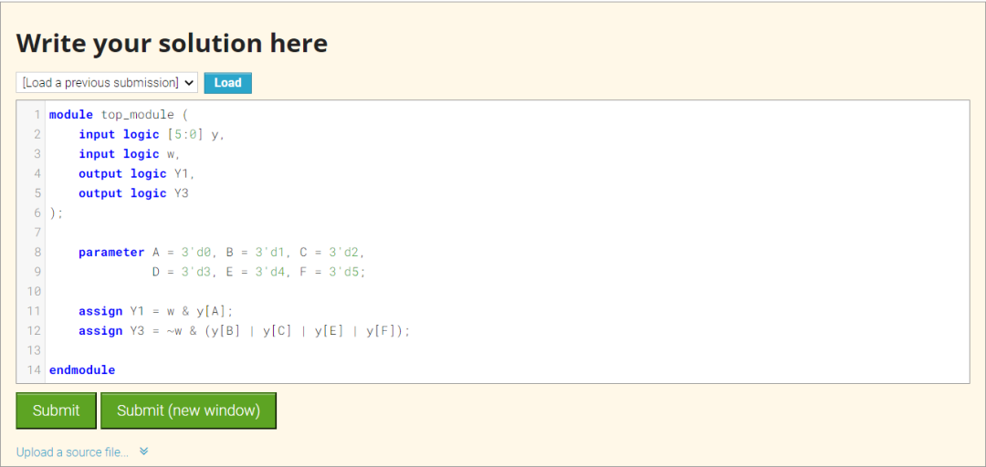
点击Submit,等待一会就能看到下图结果:
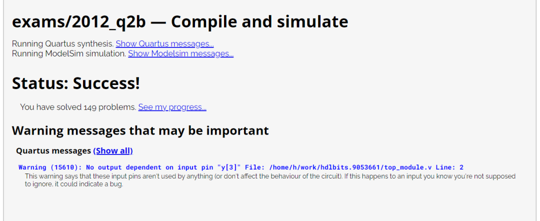
注意图中无波形。
这一题就结束了。
Problem 149-23_ece241_2014_q5b
题目说明
本题需要实现一个如下图的状态机。
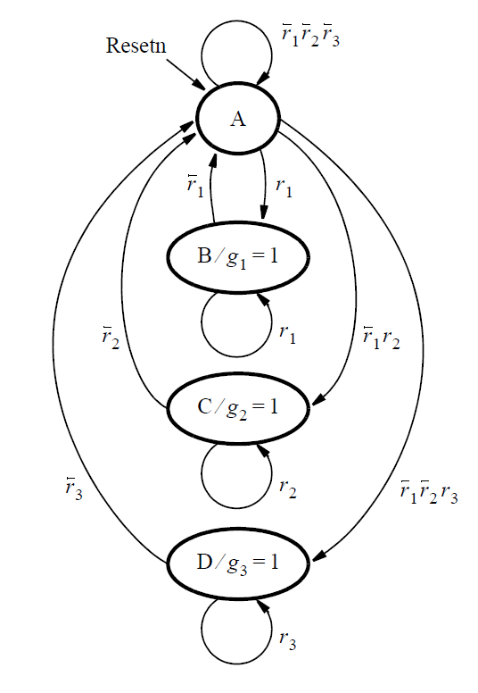 图片来自HDLBits
本状态机扮演一个仲裁电路,控制三个设备对于某种资源的访问权限。
每个设备通过置起 r[i] 信号为 1'b1 来表示对这种资源的请求。r[1],r[2].r[3]分别对应三个设备的请求信号。三个请求信号作为 FSM 的输入信号。
FSM 在没有任何请求时处于状态 A。当出现了一个或多项请求时,由 FSM 决定哪台设备获得资源的,并向其发出许可信号 g[i],置为 1'b1。g[i] 信号是 FSM 的输出信号。
本系统存在优先级,设备 1 拥有最高权限,设备 2 次之,设备 3 的权限最低。因此设备 3 只能在系统处于状态 A 的情况下才能获得资源访问权限。一旦设备获得 FSM 给出的许可信号后,将持续持有资源直至其将请求信号置低为止,请求信号为高期间不能被打断。
编写 Verilog 代码实现这个 FSM。分别使用两个 always 块来实现状态跳转以及状态触发器逻辑。输出逻辑可以使用 assign 连续赋值也可以使用 always 块实现,随你的便。状态编码方式也随你的便。
模块端口声明
module top_module (
    input clk,
    input resetn,    // active-low synchronous reset
    input [3:1] r,   // request
    output [3:1] g   // grant
);
题目解析
module top_module (
    input logic clk,
    input logic resetn,    // active-low synchronous reset
    input logic [3:1] r,   // request
    output logic [3:1] g   // grant
);

//define state

typedef enum logic [2:0] { A = 3'b000 , B = 3'b001 ,
                           C = 3'b010 , D = 3'b011
                         } state_def ;

state_def cur_state , next_state ;

//describe state transition use combinational logic

always_comb begin
    case (cur_state)
        A: begin
           casex (r)
               3'bxx1: begin
                   next_state = B ;
               end
               3'bx10: begin
                   next_state = C ;
               end
               3'b100: begin
                   next_state = D ;
               end
               default: begin
                   next_state = A ;
               end
           endcase
        end

        B: begin
            case (r[1])
                1'b0: begin
                    next_state = A ;
                end
                default: begin
                    next_state = B ;
                end
            endcase
        end

        C: begin
            case (r[2])
                1'b0: begin
                    next_state = A ;
                end
                default: begin
                    next_state = C ;
                end
            endcase
        end

        D: begin
            case (r[3])
                1'b0: begin
                    next_state = A ;
                end
                default: begin
                    next_state = D ;
                end
            endcase
        end

        default: begin
            next_state = A ;
        end
    endcase
end

//describe state sequencer use sequential logic

always_ff @( posedge clk ) begin
    if (!resetn) begin
        cur_state <= A ;
    end
    else begin
        cur_state <= next_state ;
    end
end


//describe output decoder use combinational logic

assign g[1] = (cur_state == B) ;
assign g[2] = (cur_state == C) ;
assign g[3] = (cur_state == D) ;

endmodule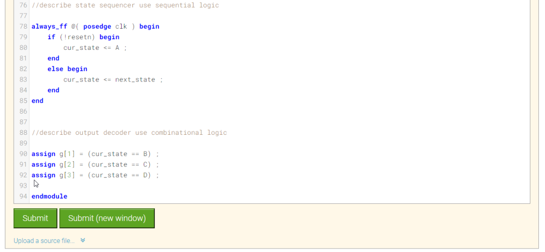
点击Submit,等待一会就能看到下图结果:
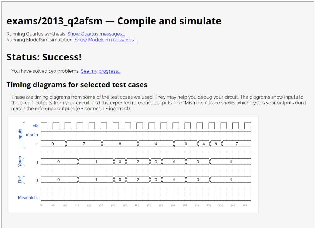
注意图中的Ref是参考波形,Yours是你的代码生成的波形,网站会对比这两个波形,一旦这两者不匹配,仿真结果会变红。
这一题就结束了。
Problem 150-2013_q2bfsm
题目说明
考虑用于控制某种类型电机的有限状态机。FSM 具有 来自电机的输入x和y ,并产生控制电机的输出f和g。还有一个称为clk的时钟输入和一个称为resetn的复位输入。
状态机电路的工作原理如下:
在复位信号有效的情况下,FSM 处于初始状态。
在复位信号移除后,FSM 在下一个时钟沿输出 f = 1,持续一个时钟周期。
接下来的,FSM 监视输入信号 x,当 x 在连续 3 个时钟周期内输出 3'b101 时,在下一周期将信号 g 置 1。
在信号 g 置 1 期间,FSM 监视输入信号 y ,如果
在接下来 2 个周期内,输入信号 y 跳变为 1'b1,那么 FSM 保持信号 g = 1 (直到复位信号到来)
输入信号 y 在 2 个时钟周期内未跳变为 1'b1,那么 FSM 保持信号 g = 0 (直到复位信号到来)
模块端口声明
module top_module (
    input clk,
    input resetn,    // active-low synchronous reset
    input x,
    input y,
    output f,
    output g
);
题目解析
module top_module (
    input logic clk,
    input logic resetn,    // active-low synchronous reset
    input logic x,
    input logic y,
    output logic f,
    output logic g
);

//define state

typedef enum logic [3:0] { IDLE = 4'd0 ,  F_OUT = 4'd1 ,  S1 = 4'd2 ,   S2 = 4'd3 ,
                           S3 = 4'd4 , S4 = 4'd5 , S5 = 4'd6 , FOREVER_ONE = 4'd7 ,
                           FOREVER_ZERO = 4'd8 } state_def ;

state_def cur_state , next_state ;

//describe state sequecer use sequential logic

always_ff @(posedge clk)begin
    if(!resetn) begin
        cur_state <= IDLE;
    end
    else begin
        cur_state <= next_state;
    end
end


//describe state transition logic use combinational logic


always_comb begin
    case(cur_state)
        IDLE:begin
            next_state = F_OUT;
        end

        F_OUT:begin
            next_state = S1;
        end

        S1:begin
            next_state = x ? S2 : S1;
        end

        S2:begin
            next_state = x ? S2 : S3;
        end

        S3:begin
            next_state = x ? S4 : S1;
        end

        S4:begin
            next_state = y ? FOREVER_ONE : S5;
        end

        S5:begin
            next_state = y ? FOREVER_ONE : FOREVER_ZERO;
        end

        FOREVER_ONE:begin
            next_state = FOREVER_ONE;
        end

        FOREVER_ZERO:begin
            next_state = FOREVER_ZERO;
        end

        default:begin
            next_state = IDLE;
        end

    endcase
end

//describe output decoder use combinational logic

assign f = (cur_state == F_OUT);
assign g = (cur_state == S4 || cur_state == S5 || cur_state == FOREVER_ONE);

endmodule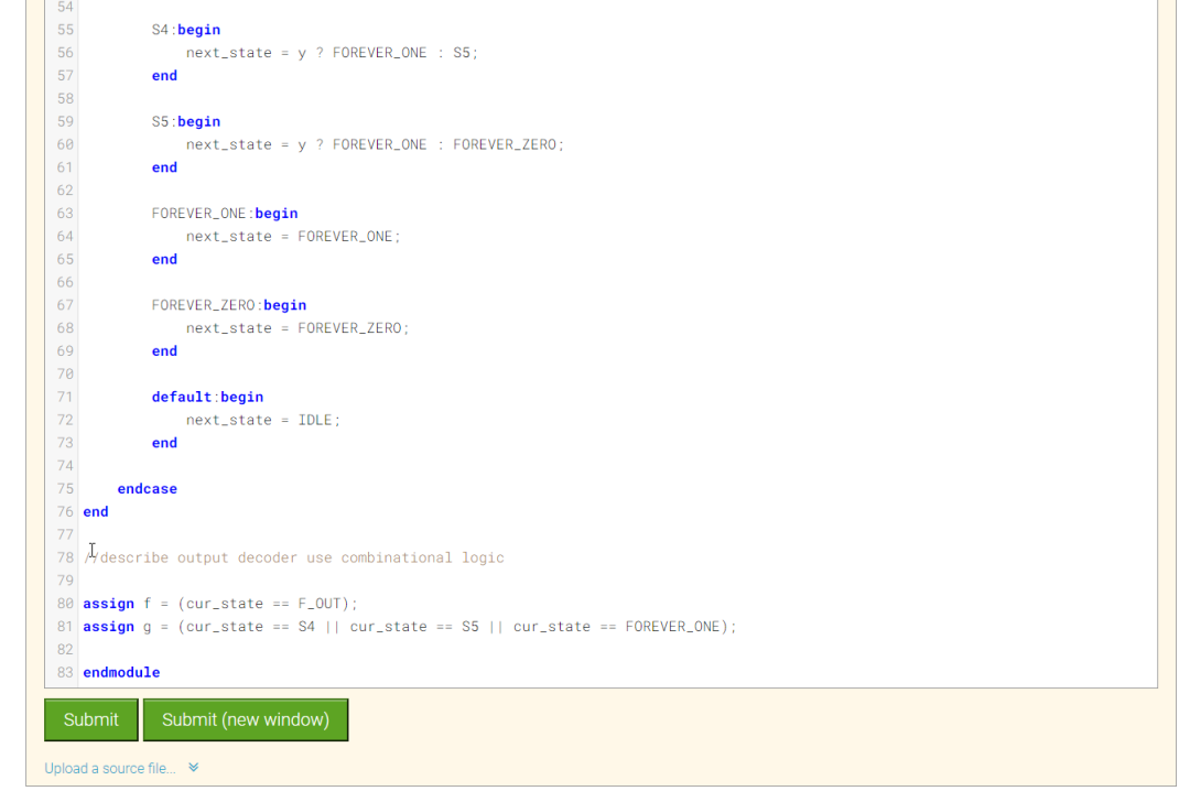
点击Submit,等待一会就能看到下图结果:
注意图中无波形。
这一题就结束了。
总结
今天的几道题就结束了,今天是状态机30多道题目中最后一篇,在解答题目遇到问题时候,试着画出状态转移图。
最后我这边做题的代码也是个人理解使用,有错误欢迎大家批评指正,祝大家学习愉快~
代码链接:
https://github.com/suisuisi/SystemVerilog/tree/main/SystemVerilogHDLBits