文章目录
20.Module
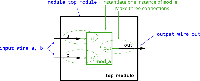
practice:You may connect signals to the module by port name or port position. For extra practice, try both methods.
两种方法:
1、You may connect signals to the module by port name
module top_module ( input a, input b, output out );
    mod_a instance1 (a, b, out);
endmodule
注:mod_a的端口与top_module的输入输出端口顺序一致,按照位置从左到右适配
2、port position
module top_module ( input a, input b, output out );
    mod_a instance2 (.out(out), .in1(a), .in2(b));
endmodule
注:这里直接将两者进行绑定
21.Connecting ports by position | Moudle pos
practice:
This problem is similar to the previous one (module). You are given a module named mod_a that has 2 outputs and 4 inputs, in that order. You must connect the 6 ports by position to your top-level module’s ports out1, out2, a, b, c, and d, in that order.
You are given the following module:
module mod_a ( output, output, input, input, input, input );
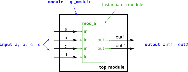
module top_module (
    input a,
    input b,
    input c,
    input d,
    output out1,
    output out2
);
    mod_a instance1 ( out1, out2, a, b, c, d );
endmodule
注:这就是简单的位置对应练习,但要仔细看题目中mod_a的顺序是先写的哪个端口,这里是output 在前面。
22.Connecting ports by name | Module name
practice:
This problem is similar to module. You are given a module named mod_a that has 2 outputs and 4 inputs, in some order. You must connect the 6 ports by name to your top-level module’s ports:
Port in mod_a Port in top_module
output out1 out1
output out2 out2
input in1 a
input in2 b
input in3 c
input in4 d
You are given the following module:
module mod_a ( output out1, output out2, input in1, input in2, input in3, input in4);
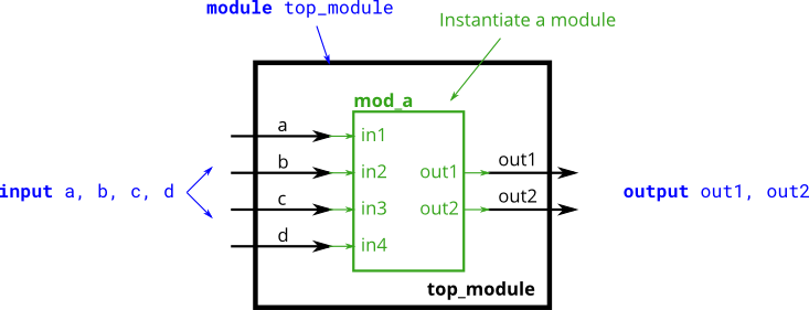
module top_module (
    input a,
    input b,
    input c,
    input d,
    output out1,
    output out2
);
    mod_a ins_mod_a ( .out1(out1), .out2(out2), .in1(a), .in2(b), .in3(c), .in4(d) );
endmodule
注:
按名称的话就不用管位置的事了,直接绑定,里面的顺序可以随意变化。
括号内格式格式:.端口名称(外部信号),
别忘了点。
23.Three modules | Module shift
practice: You are given a module my_dff with two inputs and one output (that implements a D flip-flop). Instantiate three of them, then chain them together to make a shift register of length 3. The clk port needs to be connected to all instances.
The module provided to you is: module my_dff ( input clk, input d, output q );
Note that to make the internal connections, you will need to declare some wires. Be careful about naming your wires and module instances: the names must be unique.
网络翻译:您将获得一个具有两个输入和一个输出的模块my_dff(实现 D 触发器)。实例化其中的三个,然后将它们链接在一起以形成长度为 3 的移位寄存器。clk 端口需要连接到所有实例。
提供给您的模块是:模块my_dff(输入clk,输入d,输出q);
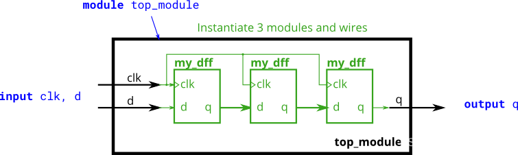
1、根据名称例化
module top_module ( input clk, input d, output q );
    wire out_q1, out_q2;
    my_dff ins_dff1 ( .clk(clk), .d(d), .q(out_q1));
    my_dff ins_dff2 ( .clk(clk), .d(out_q1), .q(out_q2));
    my_dff ins_dff3 ( .clk(clk), .d(out_q2), .q(q));
endmodule
注:这里基本就是把要用到的过程值(传输过程中),先给声明一下,后面示例模块的时候根据逻辑配对。一开始就感觉根据名称来进行模块的里化会方便一些,并且感觉根据位置是不是不可行。
2、根据位置例化
应该不行吧,但也可能是我道行还不够。
24.Modules and vectors | Module shift8
practice:This exercise is an extension of module_shift. Instead of module ports being only single pins, we now have modules with vectors as ports, to which you will attach wire vectors instead of plain wires. Like everywhere else in Verilog, the vector length of the port does not have to match the wire connecting to it, but this will cause zero-padding or trucation of the vector. This exercise does not use connections with mismatched vector lengths.
这项工作是module_shift的延伸。模块端口不是只有单个引脚,我们现在有以矢量作为端口的模块,您将在其上附加线矢量而不是普通线。与 Verilog 中的其他位置一样,端口的矢量长度不必与连接到它的导线匹配,但这会导致矢量的零填充或截断。本练习不使用矢量长度不匹配的连接。
You are given a module my_dff8 with two inputs and one output (that implements a set of 8 D flip-flops). Instantiate three of them, then chain them together to make a 8-bit wide shift register of length 3. In addition, create a 4-to-1 multiplexer (not provided) that chooses what to output depending on sel[1:0]: The value at the input d, after the first, after the second, or after the third D flip-flop. (Essentially, sel selects how many cycles to delay the input, from zero to three clock cycles.)
您将获得一个具有两个输入和一个输出的模块my_dff8(实现一组 8 D 触发器)。实例化其中三个,然后将它们链接在一起,形成长度为 3 的 8 位宽移位寄存器。此外,创建一个 4 对 1 多路复用器(未提供),该多路复用器根据 sel[1:0]:输入 d 处的值、第一个 d 之后、第二个之后或第三个 D 触发器之后的值。(本质上,sel选择延迟输入的周期数,从零到三个时钟周期。
The module provided to you is: module my_dff8 ( input clk, input [7:0] d, output [7:0] q );
The multiplexer is not provided. One possible way to write one is inside an always block with a case statement inside.
未提供多路复用器。一种可能的编写方法是在always block中,其中包含 case 语句。

module top_module (
    input clk,
    input [7:0] d,
    input [1:0] sel,
    output [7:0] q
);
    wire [7:0] out_my1, out_my2, out_my3;

    my_dff8 ins_my1 ( .clk(clk), .d(d), .q(out_my1));
    my_dff8 ins_my2 ( .clk(clk), .d(out_my1), .q(out_my2));
    my_dff8 ins_my3 ( .clk(clk), .d(out_my2), .q(out_my3));

    reg [7:0] q_t;
    always @(*)
        case(sel)
            2'b00:	q_t = d;
            2'b01:	q_t = out_my1;
            2'b10:	q_t = out_my2;
    		2'b11:	q_t = out_my3;
        endcase
    assign q = q_t;
endmodule
注:说一下这题的思考过程
1、首先这道题一上来就感觉是个综合性的题了。
2、我先是例化了三个模块,因为这个前几题接触过了,也好写,这里一开始需要声明一些wire
我先用的连续赋值直接这样写了
wire out_my1,out_my2,out_my3;
3、后面题目说要用到always和case前面听课的时候,有听到到这个知识点,但没听太明白,然后就上网和查书查看这俩的使用方法。

图片来源:https://www.runoob.com/w3cnote/verilog-process-structure.html
但这个没看太懂
最后看了case的,刚好例子就用了always,然后照着例子模仿了一下,

图片来源:https://www.runoob.com/w3cnote/verilog-case.html
并且查了一下always@(*)的用法
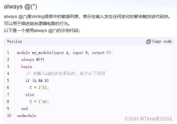
4、然后试着运行了,但编译成功,结果没全对,当case是00的结果是正确的,后面的全错,然后想了一下是不是没有定义out_my的宽度,然后改成了
wire [7:0] out_my1,out_my2,out_my3;
5、做题总结:发现还是在做题中学习是最快的,前面听课的时候不理解的现在会好理解很多。做题可以根据问题去找方法,也会更高效,期间一直在忍着不看网络上的答案。