文中若有代码、术语等错误,欢迎指正
文章目录
前言
-
此节目的
要给当前引擎添加能渲染线条、方框功能。
渲染方框是在渲染线条的基础上实现的
-
为什么
- 当前的物体包围盒需用线条、方框显示,提供友好的视觉功能
- 以后使用引擎的人员可能会需要射线检测,在编辑场景时就要看到射线的效果,相当于gizmos。
-
线条、Rect如何画
-
先说quad怎么画
OpenGL的API画Quad需要提供索引缓冲区,会有重复的索引被使用
 扫描二维码关注公众号,回复: 16210467 查看本文章
-
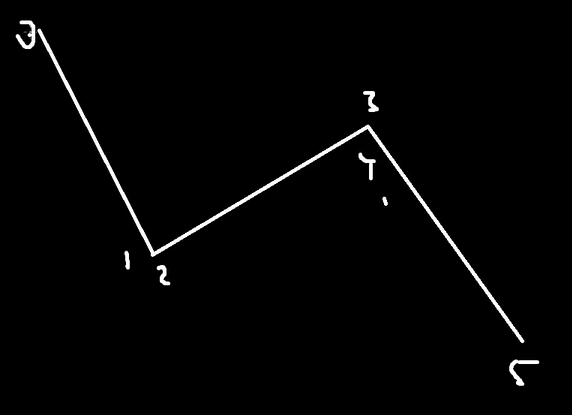
线条
使用OpenGL的API画不需要提供索引缓冲区,只需要提供顶点数组就行。
同quad一样,顶点位置可以重复利用,两个顶点位置确定一条线

-
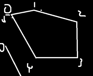
Rect
是用4条线组合而成的,一样可以重复利用顶点位置。
如下:封闭口子的最后一个位置并不需要新的顶点位置,只需要0起始点的顶点位置

-
-
如何实现
使用OpenGL的API:glDrawArrays(GL_LINES, 0, vertexCount);
-
实现细节
渲染线条需要融入当前的批处理中。
渲染线条同样需要顶点数组(顶点布局)、顶点缓冲、shader。
需开启线条光滑 glEnable(GL_LINE_SMOOTH)
可以设置线条宽度glLineWidth(width);
将Quad绘制成Rect
-
Line的glsl
// Basic Texture Shader #type vertex #version 450 core layout(location = 0) in vec3 a_Position; layout(location = 1) in vec4 a_Color; layout(location = 2) in int a_EntityID; layout(std140, binding = 0) uniform Camera{ mat4 u_ViewProjection; }; struct VertexOutput{ vec4 Color; }; layout(location = 0) out VertexOutput Output; layout(location = 1) out flat int v_EntityID; void main(){ Output.Color = a_Color; v_EntityID = a_EntityID; gl_Position = u_ViewProjection * vec4(a_Position, 1.0); } #type fragment #version 450 core layout(location = 0) out vec4 o_Color; layout(location = 1) out int o_EntityID; struct VertexOutput{ vec4 Color; }; layout(location = 0) in VertexOutput Input; layout(location = 1) in flat int v_EntityID; void main(){ o_Color = Input.Color; o_EntityID = v_EntityID; } -
实际绘制Line的opengl代码
void OpenGLRendererAPI::DrawLines(const Ref<VertexArray>& vertexArray, uint32_t vertexCount){ vertexArray->Bind(); glDrawArrays(GL_LINES, 0, vertexCount); } void OpenGLRendererAPI::SetLineWidth(float width){ glLineWidth(width); } -
批处理代码加上line的顶点数组等信息
struct LineVertex { glm::vec3 Position; glm::vec4 Color; int EntityID; }; // Line Ref<VertexArray> LineVertexArray; Ref<VertexBuffer> LineVertexBuffer; Ref<Shader> LineShader; // Line uint32_t LineVertexCount = 0;// 只需要提供顶点数量 LineVertex* LineVertexBufferBase = nullptr; LineVertex* LineVertexBufferPtr = nullptr; // Line// // 0.在CPU开辟存储s_Data.MaxVertices个的QuadVertex的内存 s_Data.LineVertexBufferBase = new LineVertex[s_Data.MaxVertices]; // 1.创建顶点数组 s_Data.LineVertexArray = VertexArray::Create(); // 2.创建顶点缓冲区,先在GPU开辟一块s_Data.MaxVertices * sizeof(QuadVertex)大小的内存 // 与cpu对应大,是为了传输顶点数据 s_Data.LineVertexBuffer = VertexBuffer::Create(s_Data.MaxVertices * sizeof(LineVertex)); // 2.1设置顶点缓冲区布局 s_Data.LineVertexBuffer->SetLayout({ { ShaderDataType::Float3, "a_Position"}, { ShaderDataType::Float4, "a_Color"}, { ShaderDataType::Int, "a_EntityID"} }); // 1.1设置顶点数组使用的缓冲区,并且在这个缓冲区中设置布局 s_Data.LineVertexArray->AddVertexBuffer(s_Data.LineVertexBuffer); // 3.索引缓冲-Line不需要索引缓冲区 s_Data.LineShader = Shader::Create("assets/shaders/Renderer2D_Line.glsl"); void Renderer2D::Flush(){ if (s_Data.LineVertexCount) { // 计算当前绘制需要多少个顶点数据 uint32_t dataSize = (uint8_t*)s_Data.LineVertexBufferPtr - (uint8_t*)s_Data.LineVertexBufferBase; // 截取部分CPU的顶点数据上传OpenGL s_Data.LineVertexBuffer->SetData(s_Data.LineVertexBufferBase, dataSize); s_Data.LineShader->Bind(); // 新增的:设置线条宽度 RenderCommand::SetLineWidth(s_Data.LineWidth); // 调用绘画命令 RenderCommand::DrawLines(s_Data.LineVertexArray, s_Data.LineVertexCount); s_Data.Stats.DrawCalls++; } } void Renderer2D::DrawLine(const glm::vec3& p0, glm::vec3& p1, const glm::vec4& color, int entityID){ s_Data.LineVertexBufferPtr->Position = p0; s_Data.LineVertexBufferPtr->Color = color; s_Data.LineVertexBufferPtr->EntityID = entityID; s_Data.LineVertexBufferPtr++; s_Data.LineVertexBufferPtr->Position = p1; s_Data.LineVertexBufferPtr->Color = color; s_Data.LineVertexBufferPtr->EntityID = entityID; s_Data.LineVertexBufferPtr++; s_Data.LineVertexCount += 2; } // 根据一点中心位置确定4个点的位置绘制rect void Renderer2D::DrawRect(const glm::vec3& position, const glm::vec2& size, const glm::vec4& color, int entityID){ // position是中心位置 glm::vec3 p0 = glm::vec3(position.x - size.x * 0.5f, position.y - size.y * 0.5f, position.z);// 左下角 glm::vec3 p1 = glm::vec3(position.x + size.x * 0.5f, position.y - size.y * 0.5f, position.z);// 右下角 glm::vec3 p2 = glm::vec3(position.x + size.x * 0.5f, position.y + size.y * 0.5f, position.z);// 右上角 glm::vec3 p3 = glm::vec3(position.x - size.x * 0.5f, position.y + size.y * 0.5f, position.z);// 左上角 DrawLine(p0, p1, color); DrawLine(p1, p2, color); DrawLine(p2, p3, color); DrawLine(p3, p0, color); } // 根据实体的transform确定顶点位置再绘制 void Renderer2D::DrawRect(const glm::mat4& transform, const glm::vec4& color, int entityID){ glm::vec3 lineVertices[4]; for (size_t i = 0; i < 4; i++) { lineVertices[i] = transform * s_Data.QuadVertexPosition[i]; // quad的顶点位置正好是rect的顶点位置 } DrawLine(lineVertices[0], lineVertices[1], color); DrawLine(lineVertices[1], lineVertices[2], color); DrawLine(lineVertices[2], lineVertices[3], color); DrawLine(lineVertices[3], lineVertices[0], color); } -
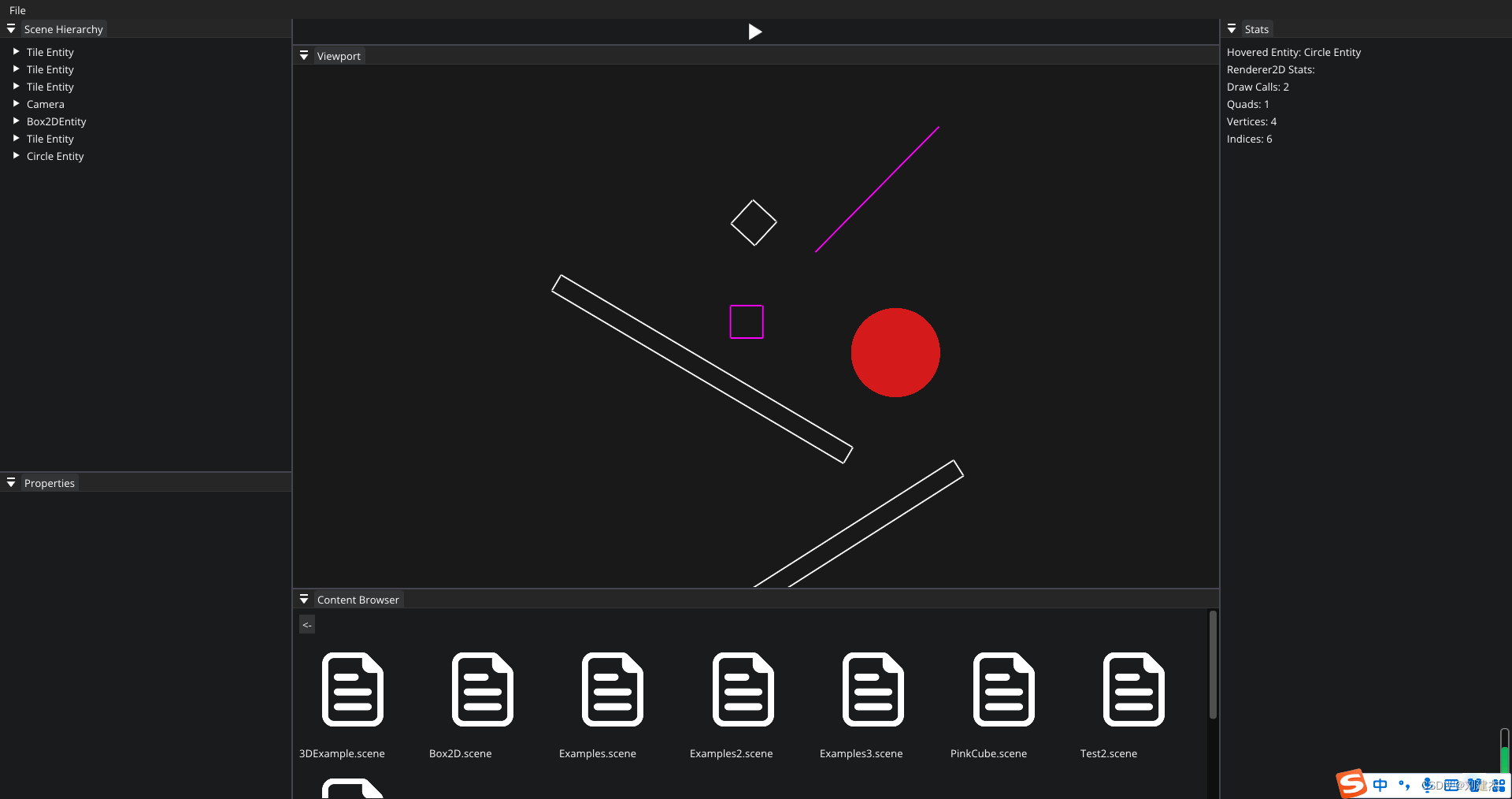
Scene场景遍历具有SpriteRendere组件的实体,遍历调用Renderer2D::DrawRect函数,并传入自身的transform确定rect的顶点位置从而绘制4个线条组成Rect
void Scene::OnUpdateEditor(Timestep ts, EditorCamera& camera)
{


    Renderer2D::BeginScene(camera);
    // 绘画sprite
    {


        auto group = m_Registry.group<TransformComponent>(entt::get<SpriteRendererComponent>);
        for (auto entity : group) {


            // get返回的tuple里本是引用
            auto [tfc, sprite] = group.get<TransformComponent, SpriteRendererComponent>(entity);
            //Renderer2D::DrawSprite(tfc.GetTransform(), sprite, (int)entity);
            //
            Renderer2D::DrawRect(tfc.GetTransform(), glm::vec4(1.0f), (int)entity);
            //
        }
    }
    // 绘画circles
    {


        auto view = m_Registry.view<TransformComponent, CircleRendererComponent>();
        for (auto entity : view) {


            // get返回的tuple里本是引用
            auto [tfc, circle] = view.get<TransformComponent, CircleRendererComponent>(entity);
            Renderer2D::DrawCircle(tfc.GetTransform(), circle.Color, circle.Thickness, circle.Fade, (int)entity);
        }
    }
    Renderer2D::DrawLine(glm::vec3(2.0f), glm::vec3(5.0f), glm::vec4(1, 0, 1, 1));
    Renderer2D::DrawRect(glm::vec3(0.0f), glm::vec3(1.0f), glm::vec4(1, 0, 1, 1));
    Renderer2D::EndScene();
}
效果
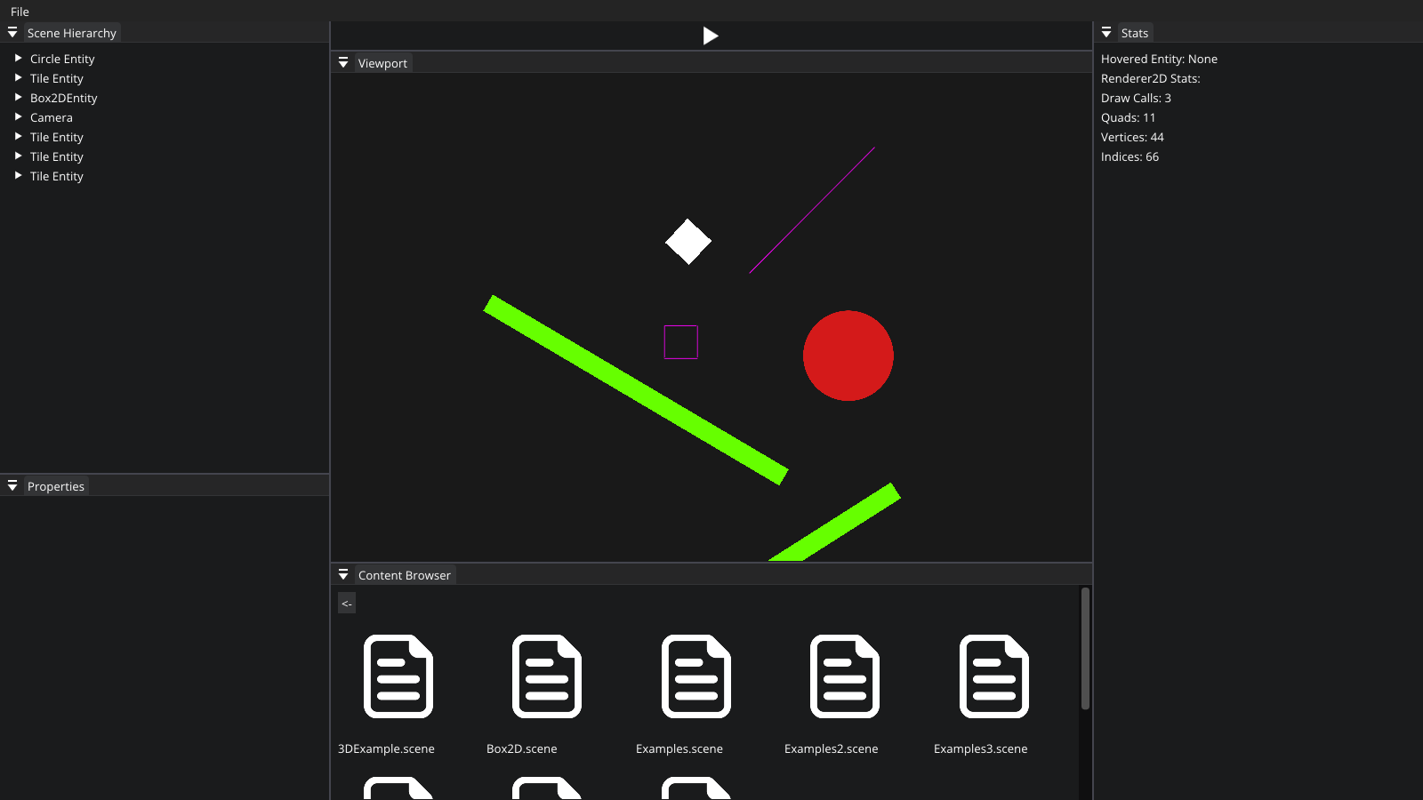
设置宽度的效果
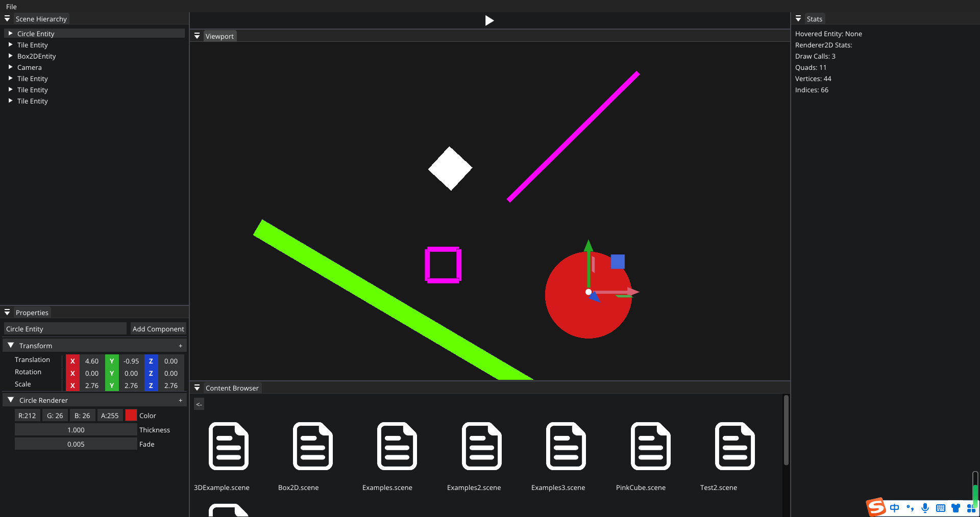
将Quad渲染成Rect的效果