文中若有代码、术语等错误,欢迎指正
前言
-
目的
实现OpenGL的批处理渲染,减少OpenGL绘制命令的调用,用一次OpenGL绘制命令,绘制多个图形
-
大致思路
CPU和GPU都开辟同样大小的一大块内存(为了存储顶点信息)
索引在程序运行时生成对应规则后绑定到索引缓冲中
动态生成顶点信息(现在改成Drawquad只是确定图形顶点的位置)
然后在Endscene,将CPU的动态生成的顶点数据上传给GPU,然后再绘制出来。
关键代码流程
-
CPU和GPU都开辟同样大小的一大块内存(为了存储顶点信息)
// 0.在CPU开辟存储s_Data.MaxVertices个的QuadVertex的内存 s_Data.QuadVertexBufferBase = new QuadVertex[s_Data.MaxVertices]; // 2.创建顶点缓冲区,先在GPU开辟一块s_Data.MaxVertices * sizeof(QuadVertex)大小的内存 // 与cpu对应大,是为了传输顶点数据 s_Data.QuadVertexBuffer = VertexBuffer::Create(s_Data.MaxVertices * sizeof(QuadVertex)); -
索引在程序运行时生成对应规则后绑定到索引缓冲中
(规则就是2个三角形组成的Quad,本来2个三角形共6个顶点,用索引后可以重复利用顶点,从而减少到4个顶点组成一个四方形)
// 3.索引缓冲 //uint32_t flatIndices[] = { 0, 1, 2, 2, 3, 0 }; uint32_t* quadIndices = new uint32_t[s_Data.MaxIndices]; // 一个quad用6个索引,012 230,456 674 uint32_t offset = 0; for (uint32_t i = 0; i < s_Data.MaxIndices; i += 6) { quadIndices[i + 0] = offset + 0; quadIndices[i + 1] = offset + 1; quadIndices[i + 2] = offset + 2; quadIndices[i + 3] = offset + 2; quadIndices[i + 4] = offset + 3; quadIndices[i + 5] = offset + 0; offset += 4; } Ref<IndexBuffer> flatIB = IndexBuffer::Create(quadIndices, s_Data.MaxIndices); // 1.2顶点数组设置索引缓冲区 s_Data.QuadVertexArray->SetIndexBuffer(flatIB); // cpu上传到gpu上了可以删除cpu的索引数据块了 delete[] quadIndices; -
动态生成顶点信息,主要是位置、纹理坐标
void Hazel::Renderer2D::DrawQuad(const glm::vec3& position, const glm::vec2& size, const glm::vec4& color) { HZ_PROFILE_FUNCTION(); / / /* 根据参数position确定当前顶点的位置,应该是基于本地空间 注意,并没有计算图形的transform来偏移顶点位置 而是手动根据position、size确定一个四方形的四个点的位置 */ // quad的左下角为起点 s_Data.QuadVertexBufferPtr->Position = position; s_Data.QuadVertexBufferPtr->Color = color; s_Data.QuadVertexBufferPtr->TexCoord = { 0.0f, 0.0f }; s_Data.QuadVertexBufferPtr++; s_Data.QuadVertexBufferPtr->Position = { position.x + size.x, position.y, 0.0f }; s_Data.QuadVertexBufferPtr->Color = color; s_Data.QuadVertexBufferPtr->TexCoord = { 1.0f, 0.0f }; s_Data.QuadVertexBufferPtr++; s_Data.QuadVertexBufferPtr->Position = { position.x + size.x, position.y + size.y, 0.0f }; s_Data.QuadVertexBufferPtr->Color = color; s_Data.QuadVertexBufferPtr->TexCoord = { 1.0f, 1.0f }; s_Data.QuadVertexBufferPtr++; s_Data.QuadVertexBufferPtr->Position = { position.x, position.y +size.y , 0.0f }; s_Data.QuadVertexBufferPtr->Color = color; s_Data.QuadVertexBufferPtr->TexCoord = { 0.0f, 1.0f }; s_Data.QuadVertexBufferPtr++; s_Data.QuadIndexCount += 6;// 每一个quad用6个索引 } -
然后在Endscene,将CPU的动态生成的顶点数据(主要是位置信息)上传给GPU,然后再绘制出来
void Hazel::Renderer2D::EndScene() { HZ_PROFILE_FUNCTION(); // 计算当前绘制需要多少个顶点数据 uint32_t dataSize = (uint8_t*)s_Data.QuadVertexBufferPtr - (uint8_t*)s_Data.QuadVertexBufferBase; // 截取部分CPU的顶点数据上传OpenGL s_Data.QuadVertexBuffer->SetData(s_Data.QuadVertexBufferBase, dataSize); Flush(); } void Renderer2D::Flush() { RenderCommand::DrawIndexed(s_Data.QuadVertexArray, s_Data.QuadIndexCount); } ...... void OpenGLVertexBuffer::SetData(const void* data, uint32_t size) { glBindBuffer(GL_ARRAY_BUFFER, m_RendererID); // 截取部分CPU的顶点数据上传OpenGL glBufferSubData(GL_ARRAY_BUFFER, 0, size, data); } -
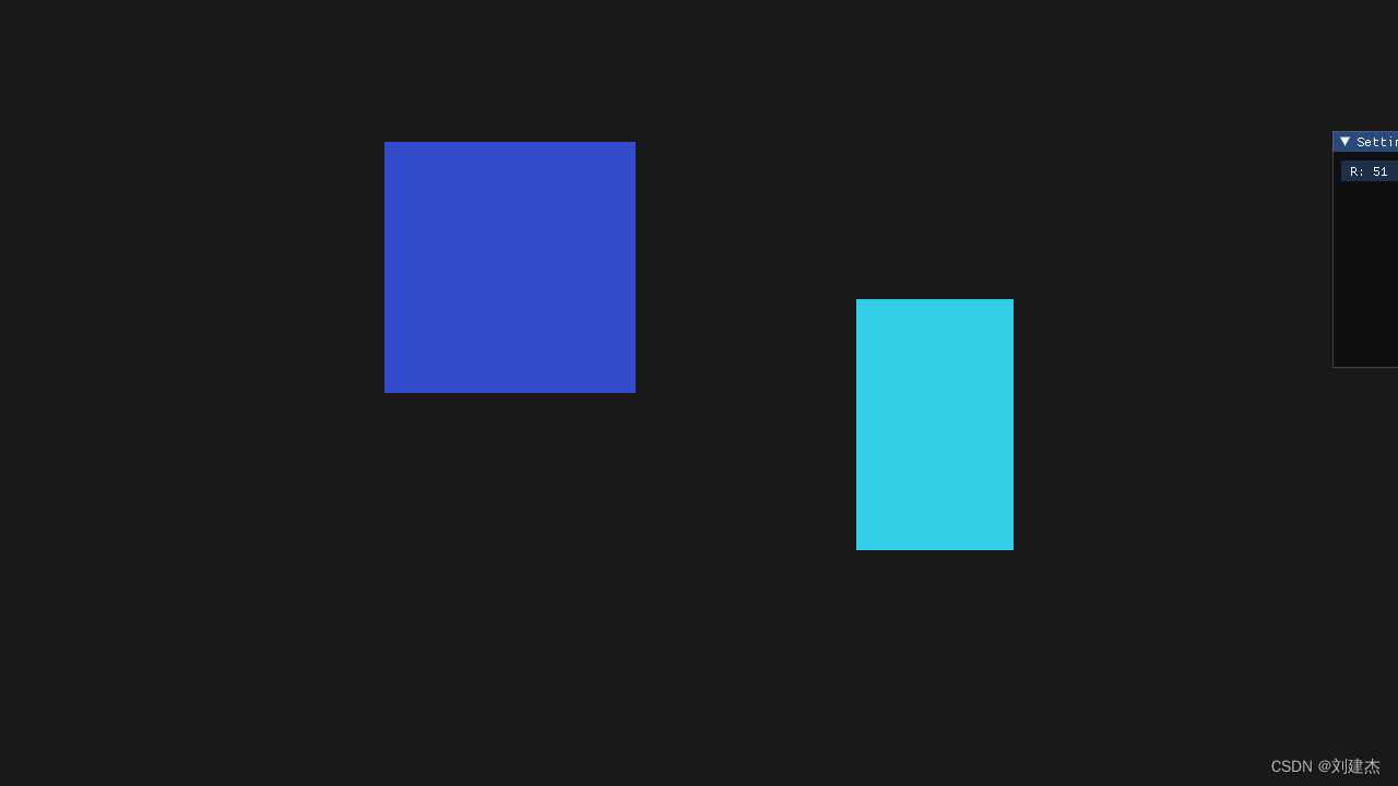
Sandbox2D
Hazel::Renderer2D::DrawQuad({ -1.0f, 0.0f }, { 0.8f,0.8f }, m_FlatColor); Hazel::Renderer2D::DrawQuad({ 0.5f, -0.5f }, { 0.5f, 0.8f }, { 0.2f, 0.8f, 0.9f, 1.0f}); -
Glsl的代码
#type vertex
#version 330 core

layout(location = 0) in vec3 a_Position;
layout(location = 1) in vec4 a_Color;
layout(location = 2) in vec2 a_TexCoord;

uniform mat4 u_ViewProjection;
// uniform mat4 u_Transform;

out vec4 v_Color;
out vec2 v_TexCoord;

void main() {


	v_Color = a_Color;
	v_TexCoord = a_TexCoord;
    // 由规则动态生成的顶点位置(基于本地空间)没有涉及transform变换顶点位置
    // gl_Position = u_ViewProjection * u_Transform * vec4(a_Position, 1.0);
	gl_Position = u_ViewProjection * vec4(a_Position, 1.0);
}
#type fragment
#version 330 core

layout(location = 0) out vec4 color;

in vec4 v_Color;
in vec2 v_TexCoord;

uniform vec4 u_Color;
uniform float u_TilingFactor;

uniform sampler2D u_Texture;

void main() {


	color = v_Color;
}
结果
完整代码
Renderer2D.cpp
#include "hzpch.h"
#include "Renderer2D.h"
#include "VertexArray.h"
#include "Buffer.h"
#include "Shader.h"
#include "Texture.h"
#include "RenderCommand.h"
#include <glm/gtc/matrix_transform.hpp>

namespace Hazel {


	struct QuadVertex {


		glm::vec3 Position;
		glm::vec4 Color;
		glm::vec2 TexCoord;
	};
    // 包含顶点的各个信息
	struct Renderer2DData{


		const uint32_t MaxQuads = 10000;
		const uint32_t MaxVertices = MaxQuads * 4;
		const uint32_t MaxIndices = MaxQuads * 6;

		Ref<VertexArray> QuadVertexArray;
		Ref<VertexBuffer> QuadVertexBuffer;
		Ref<Shader> TextureShader;
		Ref<Texture2D> WhiteTexture;

		uint32_t QuadIndexCount = 0;
		QuadVertex* QuadVertexBufferBase = nullptr;
		QuadVertex* QuadVertexBufferPtr = nullptr;
	};
	static Renderer2DData s_Data;
	void Hazel::Renderer2D::Init()
	{


		HZ_PROFILE_FUNCTION();

		// 0.在CPU开辟存储s_Data.MaxVertices个的QuadVertex的内存
		s_Data.QuadVertexBufferBase = new QuadVertex[s_Data.MaxVertices];

		// 1.创建顶点数组
		s_Data.QuadVertexArray = VertexArray::Create();

		// 2.创建顶点缓冲区,先在GPU开辟一块s_Data.MaxVertices * sizeof(QuadVertex)大小的内存
		// 与cpu对应大,是为了传输顶点数据
		s_Data.QuadVertexBuffer = VertexBuffer::Create(s_Data.MaxVertices * sizeof(QuadVertex));

		// 2.1设置顶点缓冲区布局
		s_Data.QuadVertexBuffer->SetLayout({


			{

    Hazel::ShaderDataType::Float3, "a_Position"},
			{

    Hazel::ShaderDataType::Float4, "a_Color"},
			{

    Hazel::ShaderDataType::Float2, "a_TexCoord"}
			});

		// 1.1顶点数组添加顶点缓冲区,并且在这个缓冲区中设置布局
		s_Data.QuadVertexArray->AddVertexBuffer(s_Data.QuadVertexBuffer);

		// 3.索引缓冲
		//uint32_t flatIndices[] = { 0, 1, 2, 2, 3, 0 };
		uint32_t* quadIndices = new uint32_t[s_Data.MaxIndices];

		// 一个quad用6个索引,012 230,456 674
		uint32_t offset = 0;
		for (uint32_t i = 0; i < s_Data.MaxIndices; i += 6) {


			quadIndices[i + 0] = offset + 0;
			quadIndices[i + 1] = offset + 1;
			quadIndices[i + 2] = offset + 2;

			quadIndices[i + 3] = offset + 2;
			quadIndices[i + 4] = offset + 3;
			quadIndices[i + 5] = offset + 0;

			offset += 4;
		}

		Ref<IndexBuffer> flatIB = IndexBuffer::Create(quadIndices, s_Data.MaxIndices);

		// 1.2顶点数组设置索引缓冲区
		s_Data.QuadVertexArray->SetIndexBuffer(flatIB);
		// cpu上传到gpu上了可以删除cpu的索引数据块了
		delete[] quadIndices;

		//s_Data.FlatColorShader = (Hazel::Shader::Create("assets/shaders/FlatColor.glsl"));

		// 纹理的shader
		s_Data.TextureShader = Shader::Create("assets/shaders/Texture.glsl");
		s_Data.TextureShader->SetInt("u_Texture", 0);

		// 创建一个白色Texture
		s_Data.WhiteTexture = Texture2D::Create(1, 1);
		uint32_t whiteTextureData = 0xffffffff;
		s_Data.WhiteTexture->SetData(&whiteTextureData, sizeof(uint32_t));
	}

	void Hazel::Renderer2D::Shutdown()
	{


		HZ_PROFILE_FUNCTION();

	}

	void Hazel::Renderer2D::BeginScene(const OrthographicCamera& camera)
	{


		HZ_PROFILE_FUNCTION();

		s_Data.TextureShader->Bind();		// 绑定shader
		s_Data.TextureShader->SetMat4("u_ViewProjection", camera.GetViewProjectionMatrix());

		// 相当于初始化此帧要绘制的索引数量,上传的顶点数据
		s_Data.QuadIndexCount = 0;
		// 指针赋予
		s_Data.QuadVertexBufferPtr = s_Data.QuadVertexBufferBase;
	}

	void Hazel::Renderer2D::EndScene()
	{


		HZ_PROFILE_FUNCTION();

		// 计算当前绘制需要多少个顶点数据
		uint32_t dataSize = (uint8_t*)s_Data.QuadVertexBufferPtr - (uint8_t*)s_Data.QuadVertexBufferBase;
		// 截取部分CPU的顶点数据上传OpenGL
		s_Data.QuadVertexBuffer->SetData(s_Data.QuadVertexBufferBase, dataSize);

		Flush();
	}

	void Renderer2D::Flush()
	{


		RenderCommand::DrawIndexed(s_Data.QuadVertexArray, s_Data.QuadIndexCount);
	}

	void Hazel::Renderer2D::DrawQuad(const glm::vec2& position, const glm::vec2& size, const glm::vec4& color)
	{


		DrawQuad({

     position.x, position.y, 0.0f }, size, color);
	}

	void Hazel::Renderer2D::DrawQuad(const glm::vec3& position, const glm::vec2& size, const glm::vec4& color)
	{


		HZ_PROFILE_FUNCTION();

		// quad的左下角为起点
		s_Data.QuadVertexBufferPtr->Position = position;
		s_Data.QuadVertexBufferPtr->Color = color;
		s_Data.QuadVertexBufferPtr->TexCoord = {

     0.0f, 0.0f };
		s_Data.QuadVertexBufferPtr++;

		s_Data.QuadVertexBufferPtr->Position = {

     position.x + size.x, position.y, 0.0f };
		s_Data.QuadVertexBufferPtr->Color = color;
		s_Data.QuadVertexBufferPtr->TexCoord = {

     1.0f, 0.0f };
		s_Data.QuadVertexBufferPtr++;

		s_Data.QuadVertexBufferPtr->Position = {

     position.x + size.x, position.y + size.y, 0.0f };
		s_Data.QuadVertexBufferPtr->Color = color;
		s_Data.QuadVertexBufferPtr->TexCoord = {

     1.0f, 1.0f };
		s_Data.QuadVertexBufferPtr++;

		s_Data.QuadVertexBufferPtr->Position = {

     position.x, position.y +size.y , 0.0f };
		s_Data.QuadVertexBufferPtr->Color = color;
		s_Data.QuadVertexBufferPtr->TexCoord = {

     0.0f, 1.0f };
		s_Data.QuadVertexBufferPtr++;

		s_Data.QuadIndexCount += 6;// 每一个quad用6个索引
		//s_Data.TextureShader->SetFloat4("u_Color", color);
		//s_Data.TextureShader->SetFloat("u_TilingFactor", 1.0f);
		// 绑定纹理
		//s_Data.WhiteTexture->Bind();

		// 设置transform
		/*glm::mat4 tranform = glm::translate(glm::mat4(1.0f), position) *
			glm::scale(glm::mat4(1.0f), { size.x, size.y, 1.0f });

		s_Data.TextureShader->SetMat4("u_Transform", tranform);

		s_Data.QuadVertexArray->Bind();		// 绑定顶点数组
		RenderCommand::DrawIndexed(s_Data.QuadVertexArray);*/
	}
	void Renderer2D::DrawQuad(const glm::vec2& position, const glm::vec2& size, const Ref<Texture2D>& texture, float tilingFactor, const glm::vec4& tintColor)
	{


		DrawQuad({

     position.x, position.y, 0.0f }, size, texture, tilingFactor, tintColor);
	}
	void Renderer2D::DrawQuad(const glm::vec3& position, const glm::vec2& size, const Ref<Texture2D>& texture, float tilingFactor, const glm::vec4& tintColor)
	{


		HZ_PROFILE_FUNCTION();

		s_Data.TextureShader->SetFloat4("u_Color", tintColor);
		s_Data.TextureShader->SetFloat("u_TilingFactor", tilingFactor);
		// 绑定纹理
		texture->Bind();

		// 设置transform
		glm::mat4 tranform = glm::translate(glm::mat4(1.0f), position) *
			glm::scale(glm::mat4(1.0f), {

     size.x, size.y, 1.0f });

		s_Data.TextureShader->SetMat4("u_Transform", tranform);

		s_Data.QuadVertexArray->Bind();		// 绑定顶点数组
		RenderCommand::DrawIndexed(s_Data.QuadVertexArray);
	}
	void Renderer2D::DrawrRotatedQuad(const glm::vec2& position, const glm::vec2& size, float rotation, const glm::vec4& color)
	{


		DrawrRotatedQuad({

    position.x, position.y, 0.0f}, size, rotation, color);
	}
	void Renderer2D::DrawrRotatedQuad(const glm::vec3& position, const glm::vec2& size, float rotation, const glm::vec4& color)
	{


		HZ_PROFILE_FUNCTION();

		s_Data.TextureShader->SetFloat4("u_Color", color);
		s_Data.TextureShader->SetFloat("u_TilingFactor", 1.0f);

		// 绑定纹理
		s_Data.WhiteTexture->Bind();

		// 设置transform
		glm::mat4 tranform = glm::translate(glm::mat4(1.0f), position) *
			glm::rotate(glm::mat4(1.0f), rotation, {

     0.0f, 0.0f, 1.0f }) *
			glm::scale(glm::mat4(1.0f), {

     size.x, size.y, 1.0f });

		s_Data.TextureShader->SetMat4("u_Transform", tranform);

		s_Data.QuadVertexArray->Bind();		// 绑定顶点数组
		RenderCommand::DrawIndexed(s_Data.QuadVertexArray);
	}
	void Renderer2D::DrawrRotatedQuad(const glm::vec2& position, const glm::vec2& size, float rotation, const Ref<Texture2D>& texture, float tilingFactor, const glm::vec4& tintColor)
	{


		DrawrRotatedQuad({

     position.x, position.y, 0.0f }, size, rotation, texture, tilingFactor, tintColor);
	}
	void Renderer2D::DrawrRotatedQuad(const glm::vec3& position, const glm::vec2& size, float rotation, const Ref<Texture2D>& texture, float tilingFactor, const glm::vec4& tintColor)
	{


		HZ_PROFILE_FUNCTION();

		s_Data.TextureShader->SetFloat4("u_Color", tintColor);
		s_Data.TextureShader->SetFloat("u_TilingFactor", tilingFactor);
		// 绑定纹理
		texture->Bind();

		// 设置transform
		glm::mat4 tranform = glm::translate(glm::mat4(1.0f), position) *
			glm::rotate(glm::mat4(1.0f), rotation, {

     0.0f, 0.0f, 1.0f }) *
			glm::scale(glm::mat4(1.0f), {

     size.x, size.y, 1.0f });

		s_Data.TextureShader->SetMat4("u_Transform", tranform);

		s_Data.QuadVertexArray->Bind();		// 绑定顶点数组
		RenderCommand::DrawIndexed(s_Data.QuadVertexArray);
	}
}