Table of contents
2: Independent watchdog (IWDG)
B:WWDG working characteristics
4: The difference between independent watchdog and window watchdog
1: Watchdog
1: WDG
WDG (Watchdog) watchdog ------The essence is automatic reset
The watchdog can monitor the running status of the program. When the program gets stuck or runs away due to design loopholes, hardware failures, electromagnetic interference, etc., the watchdog can reset the program in time to prevent the program from falling into a long-term strike state. Ensure system reliability and security
The watchdog is essentially a timer. When the program does not perform the dog feeding (resetting the counter - reset is not clearing) operation within the specified time range, the watchdog hardware circuit automatically generates a reset signal.
STM32 has two built-in watchdogs
Independent watchdog (IWDG): works independently and has lower requirements on time accuracy
Window watchdog (WWDG): requires the watchdog to function in a precise timing window
2: Independent watchdog (IWDG)
A:IWDG block diagram
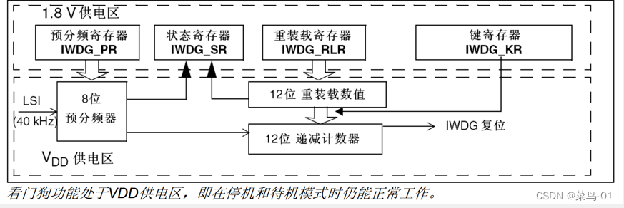
structure
Its structure is very similar to that of a timer, except that when the timer overflows, an interrupt is generated. When the watchdog timer overflows, a reset signal (IWDG reset) is directly generated. The dog feeding operation actually resets the counter. (12-bit down counter). This is a down counter that resets after it reaches 0.
When the program is running normally, in order to avoid resetting, you have to increase the count value in time before the counter (12-bit down counter) decreases to 0 - this operation is like feeding the dog. If your program is stuck If the counter is not increased in time, it will be automatically reset after it is reduced to 0.
Independent watchdog operation logic
Start: A : Input clock, which is LSI, internal low-speed clock (clock frequency is 40KHz) --------------- B: The clock enters the prescaler for frequency division (8 bits), So it can only divide by a maximum of 256; the above prescaler j register IWDG PR can configure the frequency division coefficient. This PR and the PSC of the timer (//prescaler PSC) have the same meaning ----- ------------ C: Clock-driven down counter. Every time a clock comes, it decrements by a number (12 bits, max=2^12-1=4095). Then, when it decrements to 0 After ------------- D: Generate IWDG reset;
In order to avoid reset during normal operation, we can write a value in the reload register in advance, IWDG_ RLR, which is the same as the timer's ARR (automatic reload register ARR count target value). Then when we write the value in advance, During operation, we write a specific data in this key register. When the control circuit feeds the dog, the reload value will be copied to the current counter, so that the counter will return to the reload value and decrement again. Run
Status register IWDG_SR : Marks the status of circuit operation
B:IWDG_KR key register
Key registers are essentially control registers used to control the work of hardware circuits
In the case of possible interference, the function of writing one bit in the control register is generally replaced by writing a specific value in the entire key register to reduce the probability of interference to the hardware circuit.
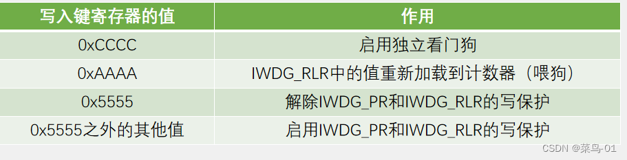
The dog feeding operation mentioned above: actually writes 0xAAAA in the key register
C:IWDG timeout
Timeout time: TIWDG = TLSI × PR prescaler coefficient × (RL + 1)
Where: TLSI = 1/FLSI

RL reload value-----The value written in the reload register IWDG_RLR
PR prescaler coefficient------equivalent to the PSC of the timer (//prescaler PSC)
RL------is equivalent to the timer's ARR (automatic reload register ARR count target value).
FLSI----is the LSI internal low-speed clock 40KHz=40 000HZ
TLSI= 1/40 000=0.000 025s = 0.025ms
calculation of time
Take the first group as an example

3: Window Watchdog (WWDG)
A:WWDG block diagram

feed the dog
The window watchdog does not reload the register. Dog feeding operation: For this, we just write data directly to CNT. We can write as much as we want.
Window watchdog operation logic
Start: A : This clock source is PCLK1 (36MHz)--------- B: First divided by a prescaler, this and the prescaler of the independent watchdog, the prescaler of the timer The frequency divider is the same --------- C : The clock after frequency division drives this counter to count (6-bit down counter).....
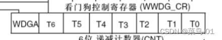
6-bit down counter
From the picture, T6~T0 is written here, a total of 7 bits. But what is written below is a 6-bit down counter---------because this counter only has T5~T0, these 6 bits are valid The count value. The highest bit T6 is used as the overflow flag here:
When the T6 bit is equal to 1, it means the counter has not overflowed.
When the T6 bit is equal to 0, it indicates that the counter overflows.
However, for hardware circuits, the T6 bit is actually part of the counter, but the T6 bit is taken out separately and used as a flag bit. EG: When the watchdog register reduces the data from 1111 111 to 1000 000 ( 16 Base representation: 0X40 ). At this time, if the T6 bit is also regarded as part of the counter, the counter value is actually reduced by half. However, if we strip off the T6 bit and use it as the overflow flag bit, the lower 6 bits, As a counter. The status at this time is that the flag bit is 1, the counter is 00 0000, which has been reduced to 0. Decrement it again and it becomes 011 1111. At this time, the highest bit T6 changes from 1 to 0-- overflow --Generate reset signal
in conclusion:
The T6 bit is regarded as part of the counter, that is, the entire counter, and the value overflows after it decreases to 0x40 (1000 000);
If you regard the T6 bit as an overflow flag and the lower 6 bits as a counter, that is, the count value of the lower 6 bits decreases to 0 and then overflows.
WDGA
WDGA------is the activation bit of the window watchdog; writing 1 to WDGA enables the window watchdog
The implementation process of the earliest time window for feeding the dog
is composed of this part of the circuit

It is necessary to calculate a count value of the earliest limit and write it into W6~W0 here. These values are fixed after writing. Once we perform a write CR operation (write watchdog control register), this is the same as The door switch opens,
Writing CR is actually writing to the counter, that is, feeding the dog. When feeding the dog, the comparator starts to work. Once it compares, our current counter T6:0>window value W6:0, the comparison result is =1 . This 1. Through the OR gate, you can also apply for reset-------This is the implementation process of the earliest time window for feeding the dog.

B:WWDG working characteristics
When the value of the down counter T[6:0] is less than 0x40, WWDG generates a reset---------T[6:0] contains the T6 bit
When the down counter T[6:0] is reloaded outside the window W[6:0], WWDG generates a reset ------ Feed the dog too early
When the down counter T[6:0] is equal to 0x40, an early wake-up interrupt (EWI) can be generated, which is used to reload the counter to avoid WWDG reset -----sent just before overflow, also called an interrupt before death---- Operations such as saving important data, shutting down dangerous equipment, etc.
Periodically write to the WWDG_CR register (feed the dog) to avoid WWDG resets

C:WWDG timeout
Timeout (latest time to feed the dog):
TWWDG = TPCLK1 × 4096 × WDGTB prescaler coefficient × (T[5:0] + 1)---T[5:0] does not include the T6 bit
Window time (earliest time to feed the dog):
TWIN = TPCLK1 × 4096 × WDGTB prescaler coefficient × (T[5:0] - W[5:0])
in:
TPCLK1 = 1 / FPCLK1

FPCLK1---36Mkz 36000 000HZ
TPCLK1-----1/36000 000
s
6-bit down counter (CNT)--------6-bit counter, the maximum value is 2^6-1=63
4: The difference between independent watchdog and window watchdog
Comparison between IWDG and WWDG

5: Data sheet
Hardware watchdog:
If the user enables the "hardware watchdog" function in the selection byte, the watchdog will automatically start running after the system is powered on and reset; if the software does not write the corresponding value to the key register before the counter ends, , the system will reset.
Window watchdog:
Start the watchdog------------After the system is reset, the watchdog is always off. Setting the WDGA bit in the WWDG_CR register can turn on the watchdog, and then it cannot be turned off unless A reset has occurred.
Controlling the down counter----------The down counter is in a free-running state. Even if the watchdog is disabled, the down counter continues to count down. When the watchdog is enabled, the TE bit must be set to prevent an immediate reset. ------- That is, when we turn it on, we must give a reload value for the first time, and set the T6 bit to 1. To prevent it from being reset immediately when turning it on.
Two: Case
A:Independent watchdog
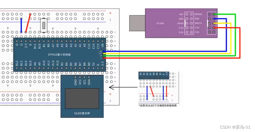
1: Connection diagram

2: Steps
1: Turn on clock LSI, internal low-speed clock (clock frequency is 40KHz) ------(If the independent watchdog has been enabled by hardware options or software, the LSI oscillator will be forced to be on and cannot be turned off. After the LSI oscillator is stable, the clock is supplied to the IWDG.) --- So the code to turn on the clock does not need to be written by us
2: Release write protection-----IWDG_KR key register
3: Write prescaler and reload values
4: Start independent watchdog----IWDG_KR key register
3: Function introduction
Independent watchdog function in the stm32f10x_iwdg.h file
void IWDG_WriteAccessCmd(uint16_t IWDG_WriteAccess);
void IWDG_SetPrescaler(uint8_t IWDG_Prescaler);
void IWDG_SetReload(uint16_t Reload);
void IWDG_ReloadCounter(void);
void IWDG_Enable(void);
FlagStatus IWDG_GetFlagStatus(uint16_t IWDG_FLAG);
IWDG_WriteAccessCmd : Write enable protection
/**
  * @brief  Enables or disables write access to IWDG_PR and IWDG_RLR registers.
  * @param  IWDG_WriteAccess: new state of write access to IWDG_PR and IWDG_RLR registers.
  *   This parameter can be one of the following values:
  *     @arg IWDG_WriteAccess_Enable: Enable write access to IWDG_PR and IWDG_RLR registers
  *     @arg IWDG_WriteAccess_Disable: Disable write access to IWDG_PR and IWDG_RLR registers
  * @retval None
  */
void IWDG_WriteAccessCmd(uint16_t IWDG_WriteAccess)
{
  /* Check the parameters */
  assert_param(IS_IWDG_WRITE_ACCESS(IWDG_WriteAccess));
  IWDG->KR = IWDG_WriteAccess;
}
Write in the IWDG_KR key register whether to enable or disable
#define IWDG_WriteAccess_Enable     ((uint16_t)0x5555)
#define IWDG_WriteAccess_Disable    ((uint16_t)0x0000)
IWDG_SetPrescaler: Set the prescaler coefficient----write in the prescaler register IWDG_PR
IWDG_SetReload: Set the reload value----write in the reload register IWDG_RLR
IWDG_ReloadCounter: Feed the dog
/**
  * @brief  Reloads IWDG counter with value defined in the reload register
  *   (write access to IWDG_PR and IWDG_RLR registers disabled).
  * @param  None
  * @retval None
  */
void IWDG_ReloadCounter(void)
{
  IWDG->KR = KR_KEY_Reload;
}
Write in IWDG_KR key register
#define KR_KEY_Reload    ((uint16_t)0xAAAA)
#define KR_KEY_Enable    ((uint16_t)0xCCCC)
IWDG_Enable : Start independent viewing
/**
  * @brief  Enables IWDG (write access to IWDG_PR and IWDG_RLR registers disabled).
  * @param  None
  * @retval None
  */
void IWDG_Enable(void)
{
  IWDG->KR = KR_KEY_Enable;
}
/* KR register bit mask */ #define KR_KEY_Reload ((uint16_t)0xAAAA) #define KR_KEY_Enable ((uint16_t)0xCCCC)
IWDG_GetFlagStatus: Check the interrupt flag bit
3: Code
#include "stm32f10x.h"                  // Device header
#include "Delay.h"
#include "OLED.h"
#include "Key.h"
int main(void)
{
	OLED_Init();
	Key_Init();

	OLED_ShowString(1, 1, "IWDG TEST:");
	if (RCC_GetFlagStatus(RCC_FLAG_IWDGRST)==SET)
	{
		/*独立看门狗复位现象
		RCC_FLAG_IWDGRST---看门狗复位标志位
		*/

		OLED_ShowString(2, 1, "IWDG TEST:");
		Delay_ms(500);
		OLED_ShowString(2, 1, "           ");
		Delay_ms(100);
		RCC_ClearFlag();
	}
	else
	{
		/*32自带的复位按键现象*/

		OLED_ShowString(4, 1, "RTC:");
		Delay_ms(500);
		OLED_ShowString(4, 1, "           ");
		Delay_ms(100);
	}
	IWDG_WriteAccessCmd(IWDG_WriteAccess_Enable);//解除写保护
	IWDG_SetPrescaler(IWDG_Prescaler_16);  //写入预分频器的值
	IWDG_SetReload(2499);//1000=0.025*16*(重装载寄存器+1)最长喂狗时间
	IWDG_ReloadCounter();//喂狗
	IWDG_Enable();//启动看门狗就是在键寄存器里面写入0XCCCC
	//也就是0X5555之外的值,也就是开启写保护 , 所以我们不写写开启写保护了;
	while (1)
	{
			Key_GetNum();
			IWDG_ReloadCounter();//喂狗
			Delay_ms(800);
	}
}
B:Window watchdog
1: Connection diagram
2: Steps
1: Turn on the window watchdog clock---PCLK1(36MHz)
2: Configuration registers--for example, prescaler, and window value
3: Write to control odd register CR
3: Code
#include "stm32f10x.h"                  // Device header
#include "Delay.h"
#include "OLED.h"
#include "Key.h"
int main(void)
{
	OLED_Init();
	Key_Init();

	OLED_ShowString(1, 1, "WWDG TEST:");
	if (RCC_GetFlagStatus(RCC_FLAG_WWDGRST)==SET)
	{
		/*独立看门狗复位现象
		RCC_FLAG_WWDGRST---窗口门狗复位标志位
		*/

		OLED_ShowString(2, 1, "WWDG TEST:");
		Delay_ms(500);
		OLED_ShowString(2, 1, "           ");
		Delay_ms(100);
		RCC_ClearFlag();
	}
	else
	{
		/*32自带的复位按键现象*/

		OLED_ShowString(4, 1, "RTC:");
		Delay_ms(500);
		OLED_ShowString(4, 1, "           ");
		Delay_ms(100);
	}
	//1: 开启时钟
	RCC_APB1PeriphClockCmd(RCC_APB1Periph_WWDG, ENABLE);
	//2: 配置寄存器
	WWDG_SetPrescaler(WWDG_Prescaler_8); //预分频器的值
	//WWDG_SetWindowValue()
	WWDG_Enable(0x40 | 53);//把T6位当作标志位来计算的0x40--T6位置1
	/*
	超时时间(喂狗的最晚时间)
	TWWDG = TPCLK1 × 4096 × WDGTB预分频系数 × (T[5:0] + 1)---T[5:0]不包含T6位
	超时时间50ms=1/36000 KHZ  * 4096 *8 *(T[5:0] + 1)
	*/
	WWDG_SetWindowValue(0x40 | 21);  //30ms
	/*
	窗口时间(喂狗的最早时间):

	TWIN = TPCLK1 × 4096 × WDGTB预分频系数 × (T[5:0] - W[5:0])
	30=1/36000KHZ*4096*8*(53-W[5:0])

	*/
	while (1)
	{
			Key_GetNum();
			Delay_ms(38);
			WWDG_SetCounter(0x40 | 53);
		/*
		窗口看门狗没有重装寄存器 ,喂狗操作
		这个,我们直接在CNT写入数据就行了 想写多少就写多少
		*/

	}
}