Final Review Summary of Computer Composition Principles
Features of a von Neumann computer:
-
Five components: arithmetic unit, memory, controller, input device, output device;
-
Machines are operator-centric (modern machines are memory-centric);
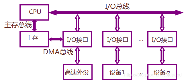
Modern computers:
-
It can be composed of three parts: CPU, I/O device and main memory;
-
Host: CPU and main memory (memory);
-
I/O devices: external devices (external memory, input devices, output devices);
ALU (arithmetic logic unit)
ACC (accumulator)
MAR (memory address register)
MDR (memory data register)
Controller (PC IR CU)
PC (Program Counter) stores the address
of the pre-executed instruction IR (Instruction Register) Stores the pre-executed instruction
CU (Control Unit)
Storage unit: store a string of binary codes;
storage word: combination of binary codes in the
storage unit; storage word length: the number of digits of the binary code in the storage unit, and each storage unit is given an address number;
Small and medium-scale integrated circuit third-generation computer
Single bus structure:

double bus structure:
three bus structure:
bus classification:
-
On-chip bus
-
System bus:
-
Data Bus;
-
address bus;
-
control bus;
- communication bus;
Bus Features:
- machine characteristics;
- electrical characteristics;
- functional characteristics;
- time characteristics;
Bus multiplexing : The address bus and the data bus share a set of physical lines;
Bus standard : ISA, EISA, VESA, PCI, AGP, RS-232C (serial communication bus standard), USB
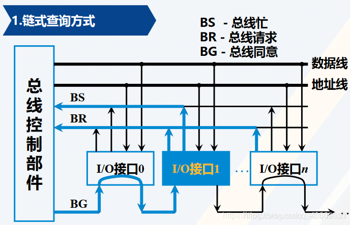
Bus arbitration control can be divided into centralized and distributed
Chain query: (circuit fault sensitive)
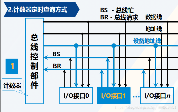
Counter timing query:
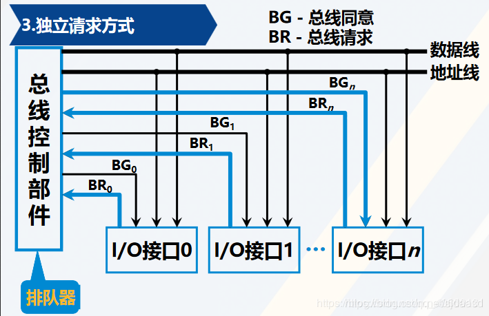
independent request mode: fast response
bus cycle:
- Application allocation stage—"Addressing stage----"Data transmission stage----"End stage
Bus communication control mode:
- synchronous communication;
- Asynchronous communication; { response mode : no interlock, half interlock, full interlock; }
- semi-synchronous communication;
- separate communication;
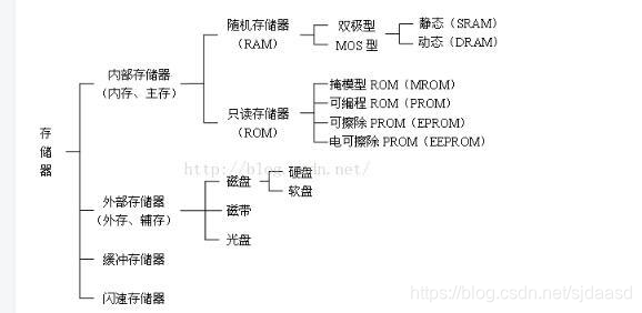
memory
RAM (Random Access Memory)
ROM (Read Only Memory)
The address line is unidirectional input; the
data line is bidirectional input;
Decoding drive mode : line selection method and overlapping method;
Regeneration or refresh: the process of restoring the original state once;
Refresh of dynamic RAM:
- centralized refresh;
- Scatter refresh;
- Asynchronous refresh;
Mask ROM (the original state cannot be changed by the user)
PROM (one-time programmable read only memory)
EPROM (erasable programmable read only memory)
Book (Principles of Computer Composition, Second Edition) Example 4.1
Verification of the memory:
It is known that the received Hamming code is 0110101 (configured according to the spouse principle), what is the sent information?
| binary serial number | 1 2 3 4 5 6 7 |
|---|---|
| Hamming code | 0 1 1 0 1 0 1 |
p1=1 XOR 3 XOR 5 XOR 7=1
p2=2 XOR 3 XOR 6 XOR 7=1
p4=4 XOR 5 XOR 6 XOR 7=0
p4p2p1=011, bit 011(3) is wrong, corrected to 0100101, the information sent is: 0101;
Address mapping:
- Direct mapping:
- Fully associative mapping:
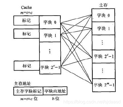
- Group associative mapping:
Channel instructions are the instructions of the channel itself;
I/O instructions are a different part of the CPU instruction system;
I/O device addressing mode: unified addressing (no dedicated I/O instructions) and non- uniform addressing (dedicated I/O instructions)
Program query mode: (stepping and waiting, CPU and I/O serial work)
Program interrupt mode: (no stepping and waiting, interrupting the current program)
DMA mode:
Steal or embezzle : CPU always cedes bus ownership to DMA
Interrupt trigger EINT is "1", the trigger can be used to open the interrupt instruction (open interrupt)
or close the interrupt instruction or hardware automatic reset (close interrupt)
Interrupt time: the end time of the instruction execution phase
Interrupt processing process:
Interrupt Request—"Interrupt Arbitration—"Interrupt Response—"Interrupt Service—"Interrupt Return
Interrupt service routine flow:
-
Protect the scene
-
Out of service
-
restore the scene
-
return from interrupt
DMA transfer process: preprocessing, data transfer, postprocessing
The program interrupt mode is transmitted by the program , and the DMA mode is transmitted by the hardware ;
The program interrupt mode is to respond at the end of an instruction execution, and the DMA mode is to respond at the end of any access cycle within the instruction cycle;
The calculation method of the computer: the
value is a positive number: the original code, the inverse code, and the complement code are the same; the sign bit is "0" and the
value is negative: the inverse code is the "inverse of each bit" of the original code, and the complement code is "inverted and added" 1"; the sign bit is "1"
Let the floating-point number be 16 bits long, with 5 digits for the exponent (including a 1-digit order sign), and 11 digits for the mantissa (including a 1-digit sign); write decimal + (13)/(128) as fixed-point numbers and floating-point numbers , and write its machine number form in fixed-point and floating-point machines, respectively.
+(13)/(128) = + (13) / ( 2^7) = 0, 0001101
Binary form: x = 0.0001101 000 (mantissa 11 digits (including 1 digit sign))
Fixed-point number: x=0.0001101000
FloatingNormalization: x = 0.1101000000x(2^-11) (binary: -11 (-3))
Fixed point machine: [x] original = [x] inverse = [x] complement
In a floating-point machine with 5 digits of order code bits (including 1 order sign)
:
[x] original = 1, 0011: 0.1101000000
[x] inverse = 1, 1100: 0.1101000000
[x] complement = 1, 1101: 0.1101000000
Given x=-0.1110, y=-0.1101, find [x y] original *
[x] original=1.1110 x*=0.1110 (absolute value) x0=1 (sign bit)
[y] original=1.1101 y*=0.1101 (absolute value) y0=1 (sign bit)
sign bit x0 XOR y0 = 0
x* xy* = 0.10110110
[x*y] original = 0.10110110
========================================================================================================
command system
Instructions are composed of opcodes and datacodes
Instruction word length = length of opcode + length of operand address + number of operand addresses
The number of bits in the register can reflect the machine word length
Instruction Addressing:
Data Addressing:
- address immediately
- direct addressing
- implicit addressing
- indirect addressing
- register addressing
- register indirect addressing
- base addressing
- Indexed addressing
- relative addressing
RISC: Reduced Instruction System Computer
CISC: Complex Instruction System Computer
Instruction cycle:
- fetch cycle
- 【Interval period】
- execution cycle
- 【Interrupt period】
Interrupt arbitration can be implemented in hardware or software;
Protecting program breakpoints is to save the contents of the current program counter PC in the memory;
Interrupt implicit instructions are done automatically by hardware;
========================================================================================================
It is assumed that a non-bus structure is used inside the CPU;
(1)取指周期的全部微操作
PC->MAR
1-R
M(MAR)->MDR
MDR->IR
OP(IR)->CU
(PC)+1->PC
(2)  取数指令“LDA M"操作:
Ad(IR) -> MAR
1->R
M(MAR)->MDR
MDR->ACC
(3)存数指令"STA M"操作
Ad(IR)->MAR
1->W
ACC->MDR
MDR->M(MAR)
(3)加法指令"ADD M”操作
Ad(IR)->MAR
1-R
M(MAR)->MDR
(ACC)+(MDR)->ACC
(4)  指令为间接寻址时,需要添加间址周期操作
Ad(IR)->MAR
1-R
M(MAR)->MDR
进入执行周期,3条指令的第一个微操作均为MDR->MAR,其余操作不变;
(5)  无条件转移指令"JMP Y"
Ad(IR) - >PC
结果为零的移指令“BAZ  Y"
Z*Ad(IR)->PC***
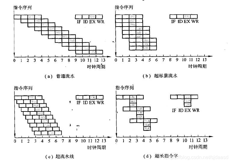
Instruction cycle consists of several machine cycles
Machine cycle consists of several clock cycles
One machine instruction corresponds to one microprogram
Microinstruction format:
| Operation control | Sequence control |
|---|
divided into
| horizontal microinstruction | vertical microinstruction |
|---|
===================================================== ===================================================== ====
In a micro-program controller, the micro-instruction format of the horizontal direct control (coding) method is adopted, and the address of the subsequent micro-instruction is given by the lower address field of the micro-instruction. The known machine has a total of 28 micro-commands, 6 mutually exclusive and determinable external conditions, and the capacity of the control memory is 512X40 bits. Design the microinstruction format and explain the reasons;
| Operation control | judge | next address |
|---|---|---|
| 28th place | 3rd place | 9th place |
Using direct encoding, the number of bits in the operation control field is equal to the number of micro-commands, which is 28 bits;
The address of the subsequent microinstruction is given by the lower address field of the microinstruction, and the number of bits of the lower address field can be set to 9 bits according to the memory capacity (512X40 bits), 2^9=512;
6 mutually exclusive determinable external conditions, can be compiled 2^3 > 6, can be compiled into 3-bit status bits;
[Reference Document] Principles of Computer Composition Second Edition