Article Directory
- UML own summary notes, hoping small partners can pick a like oh, is not easy hand to play, thanks for the support Oh! ! ! !
1.UML Introduction
What is 1.1 UML
UML is the Unified Modeling Language abbreviation (UnifiedModelingLanguage), which was published in 1997, is a support system modeling and software development graphical language, modeling and visualization to provide support for all phases of software development.
1.2 UML Features
UML use unified, standardized marking and definition, which combines the best of today's object-oriented software modeling.
1.3 UML role
UML object-oriented software system of description and modeling .
1.4 UML difference between programming languages
UML is a follow precise grammar graphic language , unlike Java, to build a model of the system.
UML supports both forward engineering, reverse engineering is also supported.

2.UML structure
-
The basic building blocks: modeling elements i.e., the main body model.
-
UML rules: govern the rules on how the basic building blocks together.
-
Common mechanism: the mechanism used in common throughout the UML model, extension mechanism.

3.UML basic building blocks
3.1 things, relationships, chart
-
Things and clearance system known as model elements
-
A model with a different element can be used in the UML diagram
The figure below shows the basic building blocks part

3.2 UML basic building blocks - things
Building blocks is an abstract object model component representative of the most
- Structure of things: UML terms, the model of the static part
- Behavior things: dynamic part of the UML verb, model
- Packet things: UML container, used to organize model
- Notes things: explain part of the UML, the model used to describe the
3.2.1 structure of things
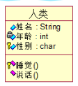
- 1. classes and objects
class is a group set with the same attributes and behavior of
a particular object is an instance of the class
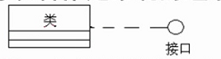
- 2. Interface
is used to describe a class of a service or set of actions to build

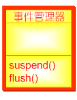
- 3. Activity class
object activity class at least have a thread or process
outermost border activity class with a thick line
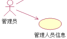
- 4. Use Example
to visualize the system requirements outlined
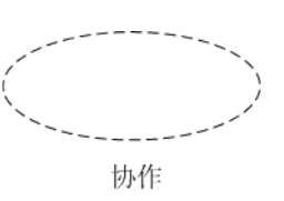
- 5. collaboration
by a group work together to provide collaborative role and behavior of elements that make up
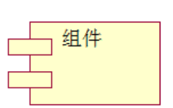
- 6. The assembly
is used to represent a large class of software entities than
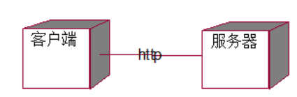
- 7. node
physical elements present in the system at runtime
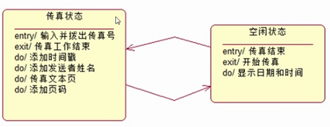
3.2.2 behavior of things
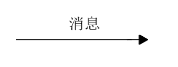
- Interaction: represented by the directional arrow with a name or content
- State Machine: The state of drawing a rounded rectangle, and write the state name and name inside the rectangular sub-state
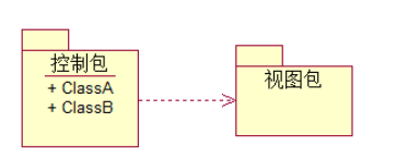
3.2.3 Packet things
- Package: a large number of medium and large class group management software
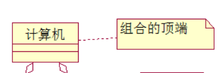
3.2.4 Notes things
- Notes: simple symbols for the elements of interpretation
3.3 UML basic building blocks - Relationship
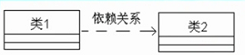
1. Dependencies
- One thing changes, it will affect the semantics of the other things
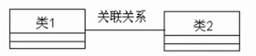
2. relationship
- Contact between objects a thing of the object and another thing
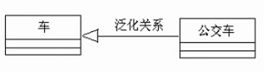
3. Generalization
- It can be seen as inheritance
4. Implement relations
- One class specified by another class element to ensure the implementation of the contract
3.4 UML basic building blocks - FIG.
3.4.1UML classification model diagram
As shown below
static FIG divided into: use case diagram, class diagram, an object diagram, package diagram, FIG member, deployment FIG. Dynamic FIG divided into: a state diagram, an activity diagram, a collaboration diagram, a sequence diagram.
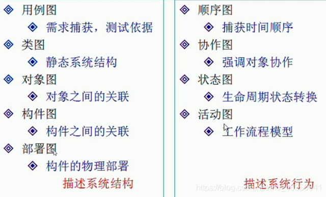
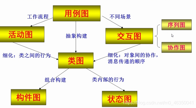
3.4.2UML nine kinds of map
- FIG using Example: Description System From a user perspective, the model is a function diagram of a system user can observe
- FIG class: class structure described static system
- FIG Object: describes the state of each object involved in the interaction at some point during the interaction of
- FIG member: description of the physical structure of the member, and the dependence of each component
- FIG Deployment: definition of the physical system architecture of the hardware and software described arrangement member is located on the node instances running instance
- FIG sequence: display the dynamic relationship between objects, the order messages sent between the stressed object
- FIG Collaboration: presentation connection and information exchange between a set of objects
- FIG Status: The status of the nodes, all show the status of a particular object, an object instance described lifecycle
- FIG Activities: Activities described workflow execution algorithms involved, emphasizes controlling the flow between objects
Figure 3.4.1UML nine kinds of integrated application