在掌握基本变换后,学习如何变换coordinate space。
对coordinate space进行变换的目的是将local space中各顶点坐标转换成normalized device coordinate (NDC),然后传递到Fragment Shader中。对于OpenGL,为了能够最终显示在屏幕上,被转换成NDC的顶点坐标的x、y和z坐标范围应当在[-1, 1],并遵循左手坐标系原则,即坐标范围超出[-1, 1]顶点,均是不可见的。coordinate space变换的步骤如下图所示: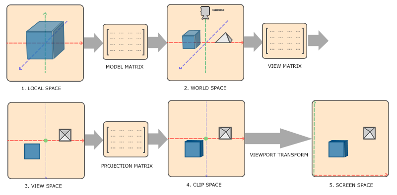
记住五个坐标系和三个矩阵!在编写程序时,也是对这三个矩阵进行操作。分别解释它们的作用:
1. model matrix
model matrix将local coordinate变换为world coordinate。想象一个等边三角形,在最开始它处于local space,坐标系原点就是三角形的中心点。当渲染多个等边三角形时,对于每个处于local space的三角形来说,坐标系原点均是自身的中心点。在对三角形进行scale、rotate和translate后,三角形被分散在了各处,并处在world space中,此时需要一个新的坐标系来表示各三角形的顶点坐标,即world coordinate。也很容易看出,在这个例子中,model matrix就是对三角形进行scale、rotate和translate的变换矩阵。
2. world matrix
world matrix将world coordinate变换为view coordinate。假设此时在world space的任一位置有一个摄像机,如果需要模拟摄像机的观察视角,则应当以摄像机的位置作为坐标系原点重新建立坐标系,而world space中其他物体和摄像机的相对位置应当保持不变。这一变换由world matrix完成,新建立的坐标系就是view coordinate。
3. projection matrix
projection matrix将view coordinate变换为clip coordinate,即NDC,所有可见顶点的坐标范围均在[-1, 1],超出这个范围的顶点都会被裁剪掉。其中顶点的z坐标表示depth value,depth value约大,则距离摄像机正面的距离越远,在渲染时由该顶点插值得到的fragment就越容易被遮挡。在程序中,需要手动使能depth test。projection matrix分为perspective projection matrix和orthographic projection matrix。
最后一步viewport transformation由OpenGL自动完成,所有可见顶点的坐标会根据窗口宽高按比例缩放,并传递到Rasterizer中。
以章节后练习第三题为例,解释代码:
渲染10个立方体,使用model matrix只让是3倍数的立方体旋转(包括第1个立方体),而让剩下的立方体保持静止。
1.
输入渲染一个立方体需要的顶点数据,包括顶点坐标,颜色和纹理坐标。一个立方体有6个面,每个面2个三角形,6个顶点数据,因此总共需要36个顶点数据才能完成一个立方体的渲染。
float vertices3[] = {
    -0.5f, -0.5f, -0.5f,  0.84f, 0.38f, 0.157f, 0.0f, 0.0f,
     0.5f, -0.5f, -0.5f,  0.84f, 0.38f, 0.157f, 1.0f, 0.0f,
     0.5f,  0.5f, -0.5f,  0.84f, 0.38f, 0.157f, 1.0f, 1.0f,
     0.5f,  0.5f, -0.5f,  0.84f, 0.38f, 0.157f, 1.0f, 1.0f,
    -0.5f,  0.5f, -0.5f,  0.84f, 0.38f, 0.157f, 0.0f, 1.0f,
    -0.5f, -0.5f, -0.5f,  0.84f, 0.38f, 0.157f, 0.0f, 0.0f,

    -0.5f, -0.5f,  0.5f,  0.84f, 0.38f, 0.157f, 0.0f, 0.0f,
     0.5f, -0.5f,  0.5f,  0.84f, 0.38f, 0.157f, 1.0f, 0.0f,
     0.5f,  0.5f,  0.5f,  0.84f, 0.38f, 0.157f, 1.0f, 1.0f,
     0.5f,  0.5f,  0.5f,  0.84f, 0.38f, 0.157f, 1.0f, 1.0f,
    -0.5f,  0.5f,  0.5f,  0.84f, 0.38f, 0.157f, 0.0f, 1.0f,
    -0.5f, -0.5f,  0.5f,  0.84f, 0.38f, 0.157f, 0.0f, 0.0f,

    -0.5f,  0.5f,  0.5f,  0.84f, 0.38f, 0.157f, 1.0f, 0.0f,
    -0.5f,  0.5f, -0.5f,  0.84f, 0.38f, 0.157f, 1.0f, 1.0f,
    -0.5f, -0.5f, -0.5f,  0.84f, 0.38f, 0.157f, 0.0f, 1.0f,
    -0.5f, -0.5f, -0.5f,  0.84f, 0.38f, 0.157f, 0.0f, 1.0f,
    -0.5f, -0.5f,  0.5f,  0.84f, 0.38f, 0.157f, 0.0f, 0.0f,
    -0.5f,  0.5f,  0.5f,  0.84f, 0.38f, 0.157f, 1.0f, 0.0f,

     0.5f,  0.5f,  0.5f,  0.84f, 0.38f, 0.157f, 1.0f, 0.0f,
     0.5f,  0.5f, -0.5f,  0.84f, 0.38f, 0.157f, 1.0f, 1.0f,
     0.5f, -0.5f, -0.5f,  0.84f, 0.38f, 0.157f, 0.0f, 1.0f,
     0.5f, -0.5f, -0.5f,  0.84f, 0.38f, 0.157f, 0.0f, 1.0f,
     0.5f, -0.5f,  0.5f,  0.84f, 0.38f, 0.157f, 0.0f, 0.0f,
     0.5f,  0.5f,  0.5f,  0.84f, 0.38f, 0.157f, 1.0f, 0.0f,

    -0.5f, -0.5f, -0.5f,  0.84f, 0.38f, 0.157f, 0.0f, 1.0f,
     0.5f, -0.5f, -0.5f,  0.84f, 0.38f, 0.157f, 1.0f, 1.0f,
     0.5f, -0.5f,  0.5f,  0.84f, 0.38f, 0.157f, 1.0f, 0.0f,
     0.5f, -0.5f,  0.5f,  0.84f, 0.38f, 0.157f, 1.0f, 0.0f,
    -0.5f, -0.5f,  0.5f,  0.84f, 0.38f, 0.157f, 0.0f, 0.0f,
    -0.5f, -0.5f, -0.5f,  0.84f, 0.38f, 0.157f, 0.0f, 1.0f,

    -0.5f,  0.5f, -0.5f,  0.84f, 0.38f, 0.157f, 0.0f, 1.0f,
     0.5f,  0.5f, -0.5f,  0.84f, 0.38f, 0.157f, 1.0f, 1.0f,
     0.5f,  0.5f,  0.5f,  0.84f, 0.38f, 0.157f, 1.0f, 0.0f,
     0.5f,  0.5f,  0.5f,  0.84f, 0.38f, 0.157f, 1.0f, 0.0f,
    -0.5f,  0.5f,  0.5f,  0.84f, 0.38f, 0.157f, 0.0f, 0.0f,
    -0.5f,  0.5f, -0.5f,  0.84f, 0.38f, 0.157f, 0.0f, 1.0f
};
2.
定义数组存放10个向量,model matrix使用这些向量将立方体translate到world space中的不同位置。
glm::vec3 cubePositions[] = {
  glm::vec3( 0.0f,  0.0f,  0.0f),
  glm::vec3( 2.0f,  5.0f, -15.0f),
  glm::vec3(-1.5f, -2.2f, -2.5f),
  glm::vec3(-3.8f, -2.0f, -12.3f),
  glm::vec3( 2.4f, -0.4f, -3.5f),
  glm::vec3(-1.7f,  3.0f, -7.5f),
  glm::vec3( 1.3f, -2.0f, -2.5f),
  glm::vec3( 1.5f,  2.0f, -2.5f),
  glm::vec3( 1.5f,  0.2f, -1.5f),
  glm::vec3(-1.3f,  1.0f, -1.5f)
};
3.
定义glm::mat4 coordTransform(std::size_t modelIndex)函数返回变换矩阵,参数std::size_t modelIndex表示model matrix的索引,需要使第1、4、7和10个model matrix随时间转动,而第2、3、5、6、8和9个矩阵则保持静止。model matrix很容易写出来:
glm::mat4 modelMatrix;
if(modelIndex % 3 == 0)
    modelMatrix = glm::rotate(glm::translate(glm::mat4(1.0f), cubePositions[modelIndex]), glm::radians(20.0f * modelIndex) + (float)glfwGetTime(), glm::vec3(1.0f, 0.0f, 0.3f));
else
    modelMatrix = glm::rotate(glm::translate(glm::mat4(1.0f), cubePositions[modelIndex]), glm::radians(20.0f * modelIndex), glm::vec3(1.0f, 0.0f, 0.3f));
经过model matrix变换,所有顶点都在world space中,假设此时摄像机的坐标为(0, 0, 4),为了以摄像机为坐标原点重新建立坐标系,需要将所有顶点沿z轴负方向translate4个单位。写出view matrix:
glm::mat4 viewMatrix = glm::translate(glm::mat4(1.0f), glm::vec3(0.0f, 0.0f, -4.0f));之后调用perspective(FoV, aspect, near, far)函数创建projection matrix,四个参数分别表示视野张开的角度,窗口宽高比,近平面位置和远平面位置。projection matrix的推导和计算可以参考OpenGL Projection Matrix的内容。这里直接调用函数即可:
glm::mat4 projectionMatrix = glm::perspective(glm::radians(45.0f), (float)window_width/(float)window_height, 0.1f, 1000.0f);最后做两次矩阵的乘法得到最终的变换矩阵并返回:
glm::mat4 transMatrix = projectionMatrix * viewMatrix * modelMatrix;4.
调用glEnable(GL_DEPTH_TEST)使能depth test,之后开始渲染:
while(!glfwWindowShouldClose(window)){

    processInput(window);
    glClearColor(0.03f, 0.4f, 0.57f, 1.0f);
    glClear(GL_COLOR_BUFFER_BIT|GL_DEPTH_BUFFER_BIT);
    glActiveTexture(GL_TEXTURE0);
    glBindTexture(GL_TEXTURE_2D, texture[0]);
    glActiveTexture(GL_TEXTURE1);
    glBindTexture(GL_TEXTURE_2D, texture[1]);
    ourShader.use();
    glUniform1f(glGetUniformLocation(ourShader.ID, "ratio"), fragmentRatio);
    for(size_t modelIndex = 0; modelIndex < 10; ++modelIndex){
        glUniformMatrix4fv(glGetUniformLocation(ourShader.ID, "transform"), 1, GL_FALSE, glm::value_ptr(coordTransform(modelIndex)));
        glDrawArrays(GL_TRIANGLES, 0, 36);
    }
    glBindVertexArray(VAO);
    glfwSwapBuffers(window);
    glfwPollEvents();
}
转载于:https://www.cnblogs.com/yiqian/p/11056459.html