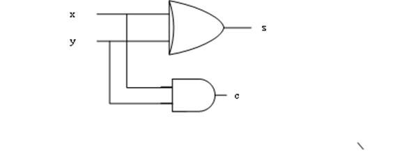
两个一位的二进制数x,y相加,假设和为s,进位为cout,其真值表为:
从真值表中,我们可以得到:s = x^y, cout = x&y,用以下的电路,可以实现两个一位数的相加,该电路称为半加器。
实现该电路的verilog代码如下:

module halfadd(x,y,s,cout);

  input x;
  input y;

  output s;
  output cout;

  assign s = x^y;
  assign cout = x&y;


endmodule
相对应的testbench文件如下代码。在代码中,我们采用系统函数$random来产生随机激励。半加器电路中并没有使用时钟,但在testbench中,产生了时钟信号,主要是为了功能验证时候,有一个时间单位信号,便于检查结果。

`timescale 1ns/1ns
`define clock_period 20

module halfadd_tb;
  reg  x,y;

  wire cout;
  wire s;
  reg clk;

  halfadd halfadd_0(
						.x(x),
						.y(y),
						.s(s),
						.cout(cout)
                  );

  initial clk = 0;
  always #(`clock_period/2) clk = ~clk;

  initial begin
     x = 0;
     repeat(20)
	    #(`clock_period) x = $random;

  end

  initial begin
     y = 0;
     repeat(20)
	    #(`clock_period) y = $random;

  end


  initial begin
     #(`clock_period*20)
	  $stop;
  end


endmodule
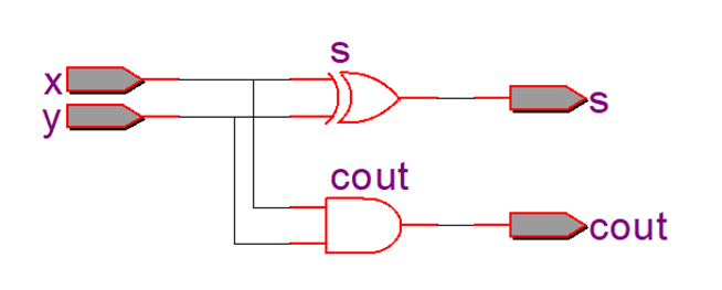
在quartus II中,分析与综合后,用rtl view 可以得到 halfadd的电路如下,和我们预想的一样。
功能仿真结果如下,从波形中可以看到结果正确。
全编译后,在Cyclone IV E-EP4CE10F17C8中的门级仿真结果如下,输入和输出之间,会有几ns的时延。


