前言
通过上一章的分析,LED能够点亮,但是程序很难理解与书写,本章使用固件库对上一章的内容改进
一、使用宏定义简化程序
宏定义的优点:
本阶段使用的是不带参数的宏定义:
1)程序容易理解,可以将复杂的宏重定义为简单的;
2)方便修改,一个宏多用时,修改值仅修改一处即可
二、STM32固件库理解
1、地址理解
下面梳理一下LED使用的寄存器宏定义的值
在手册上中查找到寄存器的基地址为0x4000 0000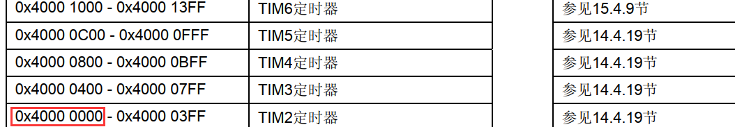
在定义宏的时候,先定义基地址,其他外设的地址根据基地址的偏移。
在固件库中,
外设基地址
#define PERIPH_BASE ((uint32_t)0x40000000) /*!< Peripheral base address in the alias region */
#define APB2PERIPH_BASE (PERIPH_BASE + 0x10000)
;APB2地址
...
#define GPIOB_BASE (APB2PERIPH_BASE + 0x0C00)
;GPIOB地址,在APB2基础上增加了0x0C00,在存储器映射中可以查找到
;//gpiox 每组寄存器
typedef struct
{
__IO uint32_t CRL;//偏移地址: 0x00
__IO uint32_t CRH;//偏移地址: 0x04
__IO uint32_t IDR;//偏移地址: 0x08
__IO uint32_t ODR;//偏移地址: 0x0C
__IO uint32_t BSRR;//偏移地址: 0x10
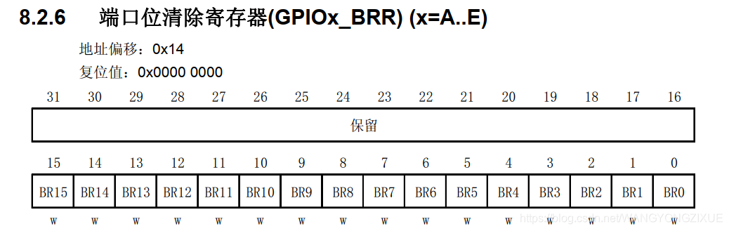
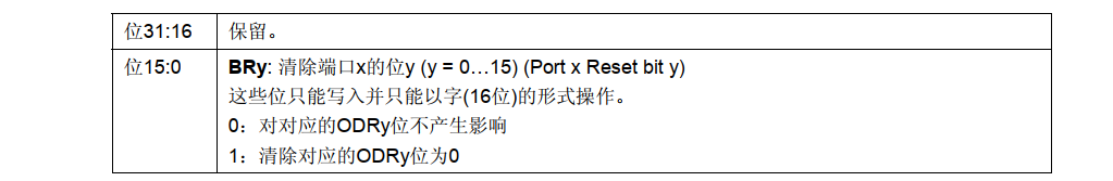
__IO uint32_t BRR;//偏移地址: 0x14
__IO uint32_t LCKR;//偏移地址: 0x18
} GPIO_TypeDef;
<font size=3>GPIO理解
;//进行GPIO_TypeDef*转换,可以直接使用GPIOB->CRL,...
#define GPIOB ((GPIO_TypeDef *) GPIOB_BASE)
2、GPIO相关理解
CPIO相关在stm32f10x_gpio.c stm32f10x_gpio.h
;GPIO引脚定义,对应ODR,IDR制定具体哪一位
#define GPIO_Pin_0                 ((uint16_t)0x0001)  /*!< Pin 0 selected */
#define GPIO_Pin_1                 ((uint16_t)0x0002)  /*!< Pin 1 selected */
#define GPIO_Pin_2                 ((uint16_t)0x0004)  /*!< Pin 2 selected */
#define GPIO_Pin_3                 ((uint16_t)0x0008)  /*!< Pin 3 selected */
#define GPIO_Pin_4                 ((uint16_t)0x0010)  /*!< Pin 4 selected */
#define GPIO_Pin_5                 ((uint16_t)0x0020)  /*!< Pin 5 selected */
#define GPIO_Pin_6                 ((uint16_t)0x0040)  /*!< Pin 6 selected */
#define GPIO_Pin_7                 ((uint16_t)0x0080)  /*!< Pin 7 selected */
#define GPIO_Pin_8                 ((uint16_t)0x0100)  /*!< Pin 8 selected */
#define GPIO_Pin_9                 ((uint16_t)0x0200)  /*!< Pin 9 selected */
#define GPIO_Pin_10                ((uint16_t)0x0400)  /*!< Pin 10 selected */
#define GPIO_Pin_11                ((uint16_t)0x0800)  /*!< Pin 11 selected */
#define GPIO_Pin_12                ((uint16_t)0x1000)  /*!< Pin 12 selected */
#define GPIO_Pin_13                ((uint16_t)0x2000)  /*!< Pin 13 selected */
#define GPIO_Pin_14                ((uint16_t)0x4000)  /*!< Pin 14 selected */
#define GPIO_Pin_15                ((uint16_t)0x8000)  /*!< Pin 15 selected */
#define GPIO_Pin_All               ((uint16_t)0xFFFF)  /*!< All pins selected */
;//gpio 速度 GPIOx_CRL/H下的MODEy
typedef enum
{


  GPIO_Speed_10MHz = 1,
  GPIO_Speed_2MHz,
  GPIO_Speed_50MHz
}GPIOSpeed_TypeDef;
;//模式 GPIOx_CRL/H 下的CNFy
typedef enum
{

     GPIO_Mode_AIN = 0x0,
  GPIO_Mode_IN_FLOATING = 0x04,
  GPIO_Mode_IPD = 0x28,
  GPIO_Mode_IPU = 0x48,
  GPIO_Mode_Out_OD = 0x14,
  GPIO_Mode_Out_PP = 0x10,
  GPIO_Mode_AF_OD = 0x1C,
  GPIO_Mode_AF_PP = 0x18
}GPIOMode_TypeDef;
;//GPIOx控制结构体,CRL/H
typedef struct
{


  uint16_t GPIO_Pin;             /*!< Specifies the GPIO pins to be configured.
                                      This parameter can be any value of @ref GPIO_pins_define */

  GPIOSpeed_TypeDef GPIO_Speed;  /*!< Specifies the speed for the selected pins.
                                      This parameter can be a value of @ref GPIOSpeed_TypeDef */

  GPIOMode_TypeDef GPIO_Mode;    /*!< Specifies the operating mode for the selected pins.
                                      This parameter can be a value of @ref GPIOMode_TypeDef */
}GPIO_InitTypeDef;

;//GPIO还提供了一系列函数,将参数传进即可
/**
  * @brief  Initializes the GPIOx peripheral according to the specified
  *         parameters in the GPIO_InitStruct.
  * @param  GPIOx: where x can be (A..G) to select the GPIO peripheral.
  * @param  GPIO_InitStruct: pointer to a GPIO_InitTypeDef structure that
  *         contains the configuration information for the specified GPIO peripheral.
  * @retval None
  */
void GPIO_Init(GPIO_TypeDef* GPIOx, GPIO_InitTypeDef* GPIO_InitStruct)
{


...
}
GPIO_ResetBits在固件库中的定义
/**
  * @brief  Clears the selected data port bits.
  * @param  GPIOx: where x can be (A..G) to select the GPIO peripheral.
  * @param  GPIO_Pin: specifies the port bits to be written.
  *   This parameter can be any combination of GPIO_Pin_x where x can be (0..15).
  * @retval None
  */
void GPIO_ResetBits(GPIO_TypeDef* GPIOx, uint16_t GPIO_Pin)
{


  /* Check the parameters */
  assert_param(IS_GPIO_ALL_PERIPH(GPIOx));
  assert_param(IS_GPIO_PIN(GPIO_Pin));

  GPIOx->BRR = GPIO_Pin;
}
3、RCC相关理解
RCC相关 在stm32f10x_rcc.c stm32f10x_rcc.h
#define RCC_APB2Periph_AFIO              ((uint32_t)0x00000001)
#define RCC_APB2Periph_GPIOA             ((uint32_t)0x00000004)
#define RCC_APB2Periph_GPIOB             ((uint32_t)0x00000008)
#define RCC_APB2Periph_GPIOC             ((uint32_t)0x00000010)
#define RCC_APB2Periph_GPIOD             ((uint32_t)0x00000020)
#define RCC_APB2Periph_GPIOE             ((uint32_t)0x00000040)
#define RCC_APB2Periph_GPIOF             ((uint32_t)0x00000080)
#define RCC_APB2Periph_GPIOG             ((uint32_t)0x00000100)
#define RCC_APB2Periph_ADC1              ((uint32_t)0x00000200)
#define RCC_APB2Periph_ADC2              ((uint32_t)0x00000400)
#define RCC_APB2Periph_TIM1              ((uint32_t)0x00000800)
#define RCC_APB2Periph_SPI1              ((uint32_t)0x00001000)
#define RCC_APB2Periph_TIM8              ((uint32_t)0x00002000)
#define RCC_APB2Periph_USART1            ((uint32_t)0x00004000)
#define RCC_APB2Periph_ADC3              ((uint32_t)0x00008000)
#define RCC_APB2Periph_TIM15             ((uint32_t)0x00010000)
#define RCC_APB2Periph_TIM16             ((uint32_t)0x00020000)
#define RCC_APB2Periph_TIM17             ((uint32_t)0x00040000)
#define RCC_APB2Periph_TIM9              ((uint32_t)0x00080000)
#define RCC_APB2Periph_TIM10             ((uint32_t)0x00100000)
#define RCC_APB2Periph_TIM11             ((uint32_t)0x00200000)
/**
  * @brief  Enables or disables the High Speed APB (APB2) peripheral clock.
  * @param  RCC_APB2Periph: specifies the APB2 peripheral to gates its clock.
  *   This parameter can be any combination of the following values:
  *     @arg RCC_APB2Periph_AFIO, RCC_APB2Periph_GPIOA, RCC_APB2Periph_GPIOB,
  *          RCC_APB2Periph_GPIOC, RCC_APB2Periph_GPIOD, RCC_APB2Periph_GPIOE,
  *          RCC_APB2Periph_GPIOF, RCC_APB2Periph_GPIOG, RCC_APB2Periph_ADC1,
  *          RCC_APB2Periph_ADC2, RCC_APB2Periph_TIM1, RCC_APB2Periph_SPI1,
  *          RCC_APB2Periph_TIM8, RCC_APB2Periph_USART1, RCC_APB2Periph_ADC3,
  *          RCC_APB2Periph_TIM15, RCC_APB2Periph_TIM16, RCC_APB2Periph_TIM17,
  *          RCC_APB2Periph_TIM9, RCC_APB2Periph_TIM10, RCC_APB2Periph_TIM11
  * @param  NewState: new state of the specified peripheral clock.
  *   This parameter can be: ENABLE or DISABLE.
  * @retval None
  */
void RCC_APB2PeriphClockCmd(uint32_t RCC_APB2Periph, FunctionalState NewState)
{


}
从函数的注释可以看到,参数可以是很多外设;GPIOA到G;USART;TIM; AFIO;ADC等等;就是系统框图 挂在到APB2下的时钟。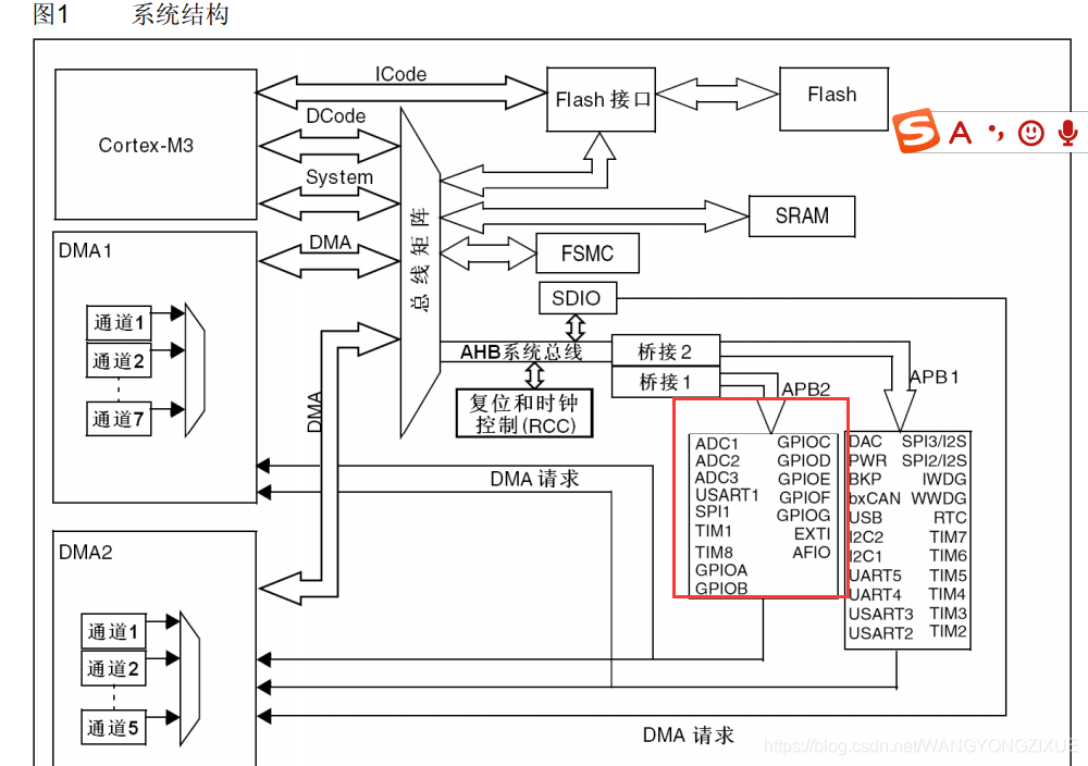
库文件还有很多模块的介绍,本文仅剖析LED相关的定义。使用官方提供的固件库函数点亮LED例子如下:
三、程序实现
bsp_led.h
扫描二维码关注公众号,回复:
12990765 查看本文章

#define LED_GPIO_PORT    	GPIOB	//端口
#define LED_GPIO_CLK 	    RCC_APB2Periph_GPIOB//时钟参数
#define LED_GPIO_PIN		GPIO_Pin_5//
bsp_led.c
#include "bsp_led.h"
void LED_GPIO_Config(void)
{


		/*定义GPIO结构体*/
		GPIO_InitTypeDef GPIO_InitStructure;

		/*开GPIOB时钟,APB2*/
		RCC_APB2PeriphClockCmd( LED_GPIO_CLK, ENABLE);
		/*具体是哪个引脚pin5*/
		GPIO_InitStructure.GPIO_Pin = LED_GPIO_PIN;
		/*GPIO模式*/
		GPIO_InitStructure.GPIO_Mode = GPIO_Mode_Out_PP;
		/*GPIO速率 */
		GPIO_InitStructure.GPIO_Speed = GPIO_Speed_50MHz;
		/*初始化GPIOB*/
		GPIO_Init(LED_GPIO_PORT, &GPIO_InitStructure);

}
main.c
int main(void)
{


	LED_GPIO_Config();//配置GPIO
	GPIO_ResetBits(LED_GPIO_PORT,LED_GPIO_PIN);// 点亮LED
}