And arithmetic circuit implementations
The basic functions of the arithmetic unit
- Complete arithmetic and logic operations
+, -, *, /, %, &, |, ~ - Calculation result obtained the state
C, Z, V, S - Output, storing the operation result
register set, data bus
The basic logic operator
- Logic gate circuit
completion logic operation - The adder
Addition is performed - Trigger
save data - Multiplexers, shifter
selection, China Unicom
Data path
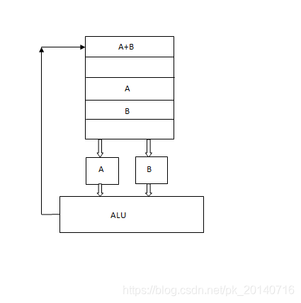
ALU functional design
- Function
of operands A, B performs an arithmetic logic operations
ADD, AND, OR - Design of
arithmetic
adder
logic operation
AND gates, OR gates
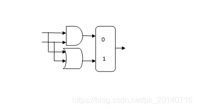
An ALU logical operations to achieve
And functions realized directly or by logic gates
multiplexer, the control signal output by the op
An adder
Three input signals: A, B, CARRYIN
2 output signals: sum, CarryOut
Truth table
| A | B | CarryIn | CarryOut | sum |
|---|---|---|---|---|
| 0 | 0 | 0 | 0 | 0 |
| 0 | 0 | 1 | 0 | 1 |
| 0 | 1 | 0 | 0 | 1 |
| 0 | 1 | 1 | 1 | 0 |
| 1 | 0 | 0 | 0 | 1 |
| 1 | 0 | 1 | 1 | 0 |
| 1 | 1 | 0 | 1 | 0 |
| 1 | 1 | 1 | 1 | 1 |
SUM = (A ' B' CARRYIN) + (A '+ B + CARRYIN) + (A + B' + CARRYIN ') + (A + B + CARRYIN)
CARRYOUT = (B CARRYIN) + (A CARRYIN) + (A * b)
with the required sum adder logic gates
logic gates required carryout
connecting together all the same input
An ALU design process
Determining the ALU function (AND, OR, NOT)
to determine the input parameters of the ALU
functional requirements, truth table, and write the logical expression
expressions logic circuit implemented according to the logic
4 ALU implementation
Connected in series with an ALU, ALU 4 to give
Lookahead generation
Other results mark
z=(f1=0)&(f2=0)&(f3=0)&(f4=0)
s=最高位
o=f1’f2’fs+f1f2fs’
Complement subtraction
The arithmetic rules
[ab &] Complement = [a] Complement + [- b] Complement
[-b] complement to the [b] +1 complement you negated
whereby we can complete the adder subtractor
