Part V Robotics, Vision and Control
It is common to talk about a robot moving to an object, but in reality the robot is only moving to a pose at which it expects the object to be. This is a subtle but deep distinction. A consequence of this is that the robot will fail to grasp the object if it is not at the expected pose. It will also fail if imperfections in the robot mechanism or controller result in the end-effector not actually achieving the end-effector pose that was specified. In order for this approach to work successfully we need to solve two quite difficult problems: determining the pose of the object and ensuring the robot achieves that pose.
The first problem, determining the pose of an object, is typically avoided in manufacturing applications by ensuring that the object is always precisely placed. This requires mechanical jigs and fixtures which are expensive, and have to be built and setup for every different part the robot needs to interact with – somewhat negating the flexibility of robotic automation.
The second problem, ensuring the robot can achieve a desired pose, is also far from straightforward. As we discussed in Chap. 7 a robot end-effector is moved to a pose by computing the required joint angles. This assumes that the kinematic model is accurate, which in turn necessitates high precision in the robot’s manufacture: link lengths must be precise and axes must be exactly parallel or orthogonal. Further the links must be stiff so they do not to deform under dynamic loading or gravity. It also assumes that the robot has accurate joint sensors and high-performance joint controllers that eliminate steady state errors due to friction or gravity loading. The non-linear controllers we discussed in Sect. 9.4.3 are capable of this high performance but they require an accurate dynamic model that includes the mass, centre of gravity and inertia for every link, as well as the payload.
None of these problems are insurmountable but this approach has led us along a path toward high complexity. The result is a heavy and stiff robot that in turn needs powerful actuators to move it, as well as high quality sensors and a sophisticated controller – all this contributes to a high overall cost. However we should, whenever possible, avoid solving hard problems if we do not have to.
Consider that the robot could see the object and its end-effector, and could use that information to guide the end-effector toward the object. This is what humans call hand-eye coordination and what we will call vision-based control or visual servo control – the use of information from one or more cameras to guide a robot in order to achieve a task.
The pose of the target does not need to be known apriori, the robot moves toward the observed target wherever it might be in the workspace. There are numerous advantages of this approach: part position tolerance can be relaxed, the ability to deal with parts that are moving comes almost for free, and any errors in the robot’s openloop accuracy will be compensated.
A vision-based control system involves continuous measurement of the target and the robot using vision to create a feedback signal and moves the robot arm until the visually observed error between the robot and the target is zero. Vision-based control is quite different to taking an image, determining where the target is and then reaching for it. The advantage of continuous measurement and feedback is that it provides great robustness with respect to any errors in the system. There are of course some practical complexities. If the camera is on the end of the robot it might interfere with the task, or when the robot is close to the target the camera might be unable to focus, or the target might be obscured by the gripper.
15 Vision-Based Control
The task in visual servoing is to control the pose of the robot’s end-effector, relative to the target, using visual features extracted from the image. As shown in Fig. 15.1 the camera may be carried by the robot or fixed in the world. The configuration of Fig. 15.1a has the camera mounted on the robot’s end-effector observing the target, and is referred to as end-point closed-loop or eye-in-hand. The configuration of Fig. 15.1b has the camera at a fixed point in the world observing both the target and the robot’s end-effector, and is referred to as end-point open-loop. In the remainder of this book we will discuss only the eye-in-hand configuration.
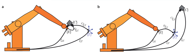
The image of the target is a function of the relative pose
. Features such as coordinates of points, or the parameters of lines of ellipses are extracted from the image and these are also a function of the relative pose
.
There are two fundamentally different approaches to visual servo control: Position-Based Visual Servo (PBVS) and Image-Based Visual Servo (IBVS). Position-based visual servoing, shown in Fig. 15.2a, uses observed visual features, a calibrated camera and a known geometric model of the target to determine the pose of the target with respect to the camera. The robot then moves toward that pose and the control is performed in task space which is commonly SE(3). Good algorithms exist for pose estimation but it is computationally expensive and relies critically on the accuracy of the camera calibration and the model of the object’s geometry. PBVS is discussed in Sect. 15.1.
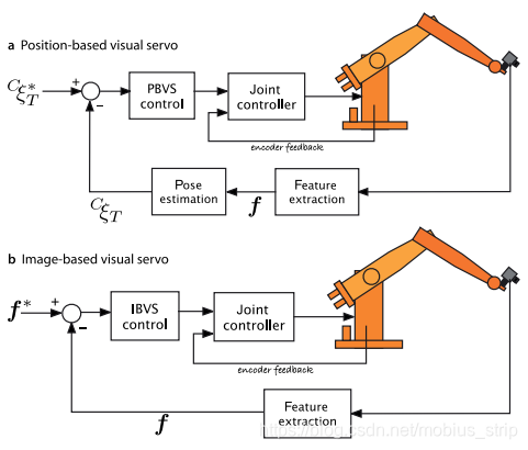
Image-based visual servoing, shown in Fig. 15.2b, omits the pose estimation step, and uses the image features directly. The control is performed in image coordinate space
. The desired camera pose with respect to the target is defined implicitly by the image feature values at the goal pose. IBVS is a challenging control problem since the image features are a highly non-linear function of camera pose. IBVS is discussed in Sect. 15.2
15.1 Position-Based Visual Servoing
In a PBVS system the pose of the target with respect to the camera
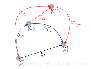
is estimated. The pose estimation problem was discussed in Sect. 11.2.3 and requires knowledge of the target’s geometry, the camera’s intrinsic parameters and the observed image plane features. The relationships between the poses is shown in Fig. 15.3. We specify the desired relative pose with respect to the target
and wish to determine the motion required to move the camera from its initial pose
to
which we call
. The actual pose of the target
is not known. From the pose network we can write
where KaTeX parse error: Got function '\hat' with no arguments as subscript at position 2: C_̲\hat{ξ}_T is the estimated pose of the target relative to the camera. We rearrange this as
which is the camera motion required to achieve the desired relative pose. The change in pose might be quite large so we do not attempt to make this movement in one step, rather we move to a point closer to
by
which is a fraction λ ∈ (0, 1) of the translation and rotation required.
In this way even if the robot has errors and does not move as requested, or the target moves the motion computed at the next time step will account for that error.
15.2 Image-Based Visual Servoing
IBVS differs fundamentally from PBVS by not estimating the relative pose of the target. The relative pose is implicit in the values of the image features. Figure 15.6 shows two views of a square target. The view from the initial camera pose is shown in red and it is clear that the camera is viewing the target obliquely. The desired view is shown in blue where the camera is further from the target and its optical axis is normal to the plane of the target – a fronto-parallel view.
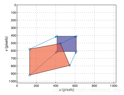
The control problem can be expressed in terms of image coordinates. The task is to move the feature points indicated by
-markers to the points indicated by
-markers. The points may, but do not have to, follow the straight line paths indicated by the arrows. Moving the feature points in the image implicitly changes the pose – we have changed the problem from pose estimation to control of points
on the image.
15.2.1 Camera and Image Motion
Earlier we expressed perspective projection in functional form Eq. 11.10

and its derivative with respect to camera pose ξ is
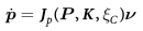
where KaTeX parse error: Expected group after '^' at position 40: … ω_y, ω_z) ∈ R6^̲& is the velocity of the camera, the spatial velocity,
which we introduced in Sect. 8.1. J p is a Jacobian-like object, but because we have taken the derivative with respect to a pose
rather than a vector it is technically called an interaction matrix. However in the visual servoing world it is more commonly called an image Jacobian or a feature sensitivity matrix.
Consider a camera moving with a body velocity ν = (v, ω) in the world frame and observing a world point P with camera relative coordinates P = (X, Y, Z). The velocity of the point relative to the camera frame is
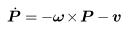
which we can write in scalar form as
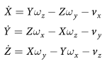
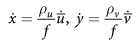
The perspective projection Eq. 11.2 for normalized coordinates is
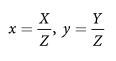
and the temporal derivative, using the quotient rule, is
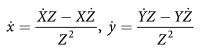
Substituting Eq. 15.2,
and
we can write this in matrix form
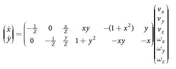
which relates camera velocity to feature velocity in normalized image coordinates.
The normalized image-plane coordinates are related to the pixel coordinates by Eq. 11.7
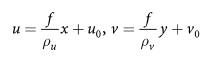
which we rearrange as
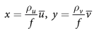
where
and
are the pixel coordinates relative to the principal
point. The temporal derivative is
and substituting Eq. 15.4 and Eq. 15.5 into Eq. 15.3 leads to
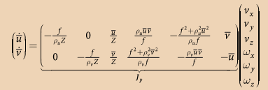
in terms of pixel coordinates with respect to the principal point. We can write this in concise matrix form as

where
is the 2 × 6 image Jacobian matrix for a point feature.
Reference
Robotics, Vision and Control: Fundamental Algorithms In MATLAB, Corke, Peter