一、简介
在上一篇中,学习了鞋底切片法来求轮廓,那个思路是比较简单的,其次还提到了法向量重建的方法,目前由于没有用法向量重建来做那个项目,所以还是有很大的疑问,后续会继续学习那个方法然后重新在做一次,和切片法做一个对比,今天来学一习Halcon 自带的例程 切平面检测物料,在上一阶中,留下来几个问题:
1、project_object_model_3d 投影模型是如何来投影的,他的数学原理是什么,记得之前我手推过一个投影矩阵,但是现在也忘记了,只记得用了正交投影,相似三角形、左手坐标系等。
2、三角化模型的原理,这个在PCL中大概看过一点,感觉看了一丁点皮毛,等有时间了系统的学一下这个知识点,从算子角度来说,三角化Halcon里面的时间有点长,就是鞋子的那个模型,三角化用了15s 的时间(Y9000),比我想象中的慢了很多,之前接触过一个做点云处理的国外同行,他说他们那边的三维重建可以控制到3s以内,当然这个和点云大小相关,但是人家有自信这么说肯定有过人之处。
二、算子解释
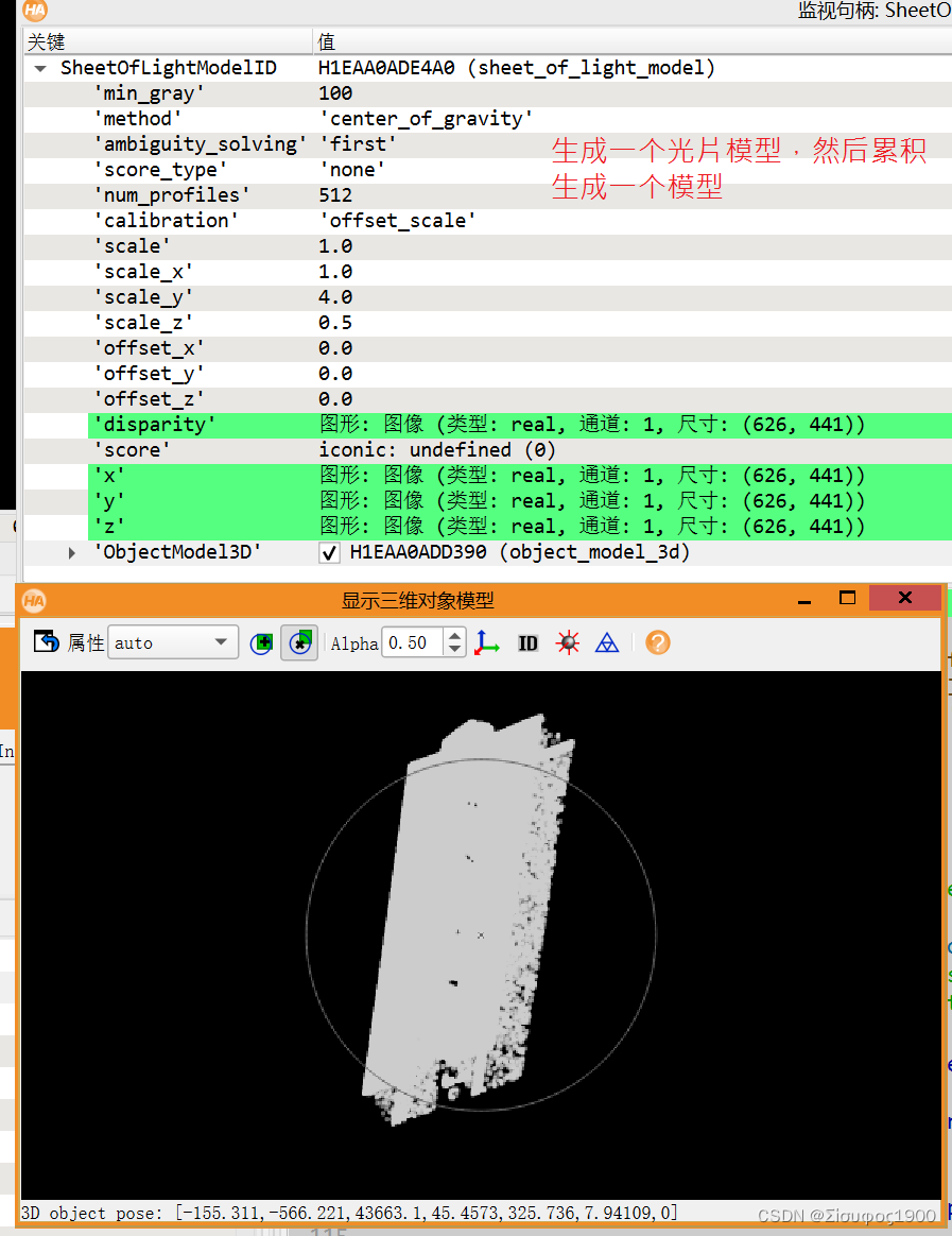
1、create_sheet_of_light_model:创建一个执行线结构光技术3D测量的光片模型
描述
操作符create_sheet_of_light_model使用线结构光技术创建一个模型来执行3d测量。该技术通过使用区域扫描摄像机和光线投影仪(通常是激光线投影仪)对不透明和漫反射固体的表面进行三维重建。照相机和放映机必须安装好,使它们的主轴形成三角形。三角测量的值通常选择在30°到60°之间。投射的光线在空间中定义了一个平面(结构光平面)。这个平面与被测量的固体表面相交,并建立了一个对摄像机可见的表面轮廓(Profile)。通过移动固体在测量系统前面,(即如照相机和激光器的组合),就有可能记录整个固体的表面。作为一种替代方案,测量系统也可以在被测表面上移动。请注意,轮廓在轮廓图像中必须大致水平定位,因为它们是逐列处理的。
如果有测量装置的几何信息,就可以计算出重建曲面的真实三维坐标。浏览所需几何图形的描述(即,标定)的信息,请参阅操作符set_sheet_of_light_param。如果没有这样的信息,测量的结果是一个视差图像(disparity image),其中每个像素保存着被测轮廓的亚像素精确位置的记录。
操作员在SheetOfLightModelID中返回光表模型的句柄,该句柄用于对光表模型的所有进一步操作,如修改模型的参数、测量轮廓、应用标定转换或访问测量结果。
使用简化的线结构光模型参数
在一个简单的设置或是否为一个真正的度量标定是必要的,观测到的视差图转换成3D值可以控制使用简化的参数集的线结构光模型:通过将set_sheet_of_light_param的校准设置为‘offset_scale’,位姿和相机参数将更改为这样的值,即一个像素的偏移量对应于3D结果中的一个单元。这允许从一个未校准的线结构光模型创建一个三维物体模型和三维图像。
从视差到三维坐标的转换可以通过六个参数来控制:‘scale_x’、‘scale_y’、‘scale_z’、‘offset_x’、‘offset_y’、‘offset_z’。有关所有受支持的通用参数的详细描述,请参阅set_sheet_of_light_param。
Halcon算子学习:create_sheet_of_light_model_Leon_Chan0的博客-CSDN博客
create_sheet_of_light_model
(ProfileRegion : : GenParamName, GenParamValue : SheetOfLightModelID)
创建一个执行线结构光技术3D测量的的模型

输入:
ProfileRegion
包含要处理的轮廓的图像的ROI。(如果所提供的区域不是矩形的,则使用其最小的外接矩形)

GenParamName
可以为线结构光模型调整的通用参数的名称。
默认值:“min_gray”
值列表:’ uity_solving’, ‘calibration’, ‘method’, ‘min_gray’, ‘num_profiles’, ‘offset_x’, ‘offset_y’, ‘offset_z’, ‘scale’, ‘scale_x’, ‘scale_y’, ‘scale_z’, ‘score_type’

GenParamValue
可以为线结构光模型调整的通用参数的值。
默认值:50
建议值:‘default’, ‘center_of_gravity’, ‘last’, ‘first’, 'bright ', ‘none’, ‘intensity’, ‘width’, ‘offset_scale’, 50,100,150,180

输出:

SheetOfLightModelID
用于使用和访问光照模型的句柄。


set_sheet_of_light_param
2、measure_profile_sheet_of_light 将配置文件图像作为输入处理,并将由此产生的差异存储到光片模型中。
measure_profile_sheet_of_light(ProfileImage : : SheetOfLightModelID, MovementPose : )
描述:
1,ProfileImage,输入图片
2,SheetOfLightModelID,光平面模型句柄
3,MovementPose
Pose 描述在以前处理过的个人资料图像和当前配置文件图像之间测量的场景移动。
* Create the rectangular region in which the profiles are measured.
gen_rectangle1 (ProfileRegion, 120, 75, 195, 710)
*
* Create a model in order to measure profiles according to
* the sheet-of-light technique. Simultaneously set some
* parameters for the model.
create_sheet_of_light_model (ProfileRegion, ['min_gray','num_profiles', 'ambiguity_solving','score_type'], [70,290,'first','width'], SheetOfLightModelID)
*
* Measure the profile from successive images
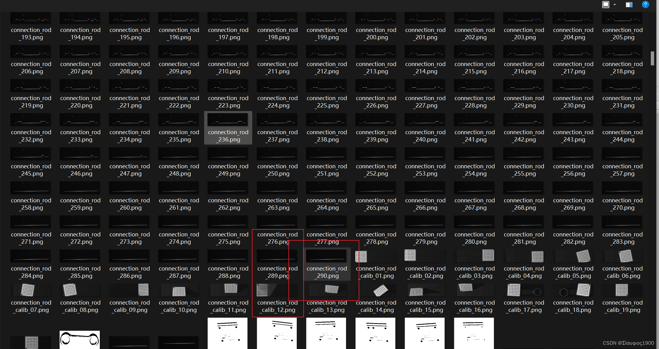
for Index := 1 to 290 by 1
read_image (ProfileImage, 'sheet_of_light/connection_rod_'+Index$'.3')
dev_display (ProfileImage)
dev_display (ProfileRegion)
measure_profile_sheet_of_light (ProfileImage, SheetOfLightModelID, [])
endfor
*
* Get the resulting disparity and score images
get_sheet_of_light_result (Disparity, SheetOfLightModelID, 'disparity')
get_sheet_of_light_result (Score, SheetOfLightModelID, 'score')
*
* Close the sheet-of-light handle once the measurement
* has been performed
clear_sheet_of_light_model (SheetOfLightModelID)
光平面图片:
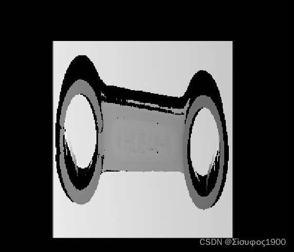
光片模型
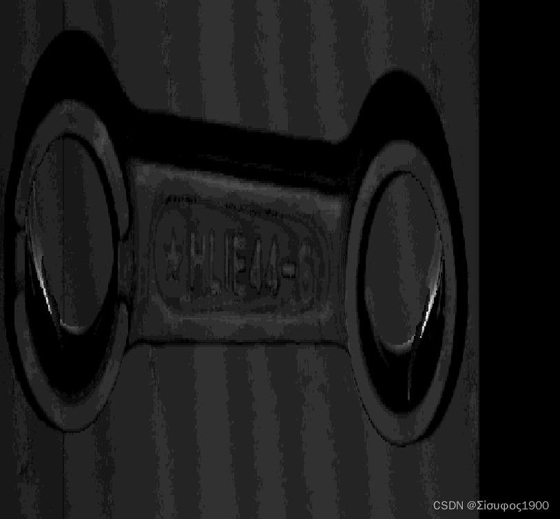
计算法向量:
Halcon 3D 计算3D模型的3D表面法线_Σίσυφος1900的博客-CSDN博客_halcon 计算点云法线
计算发向量之后的模型
三、算法思路
1、声明一个光片模型句柄
2、用这个模型句柄来把所有的都加载进行,想当与一个线激光,在不断的向前走,等线数走完之后就将生成一个模型
将光片模型生成一个常见的3D点云模型
get_sheet_of_light_result_object_model_3d (SheetOfLightModelID, Model3DFull)3、去噪点
4、表面法向量计算与重建
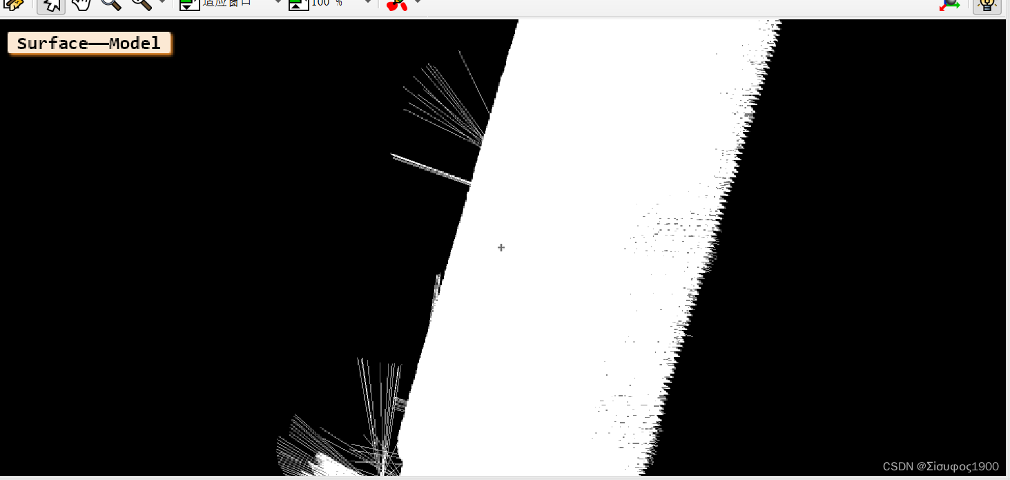
* 表面法向量
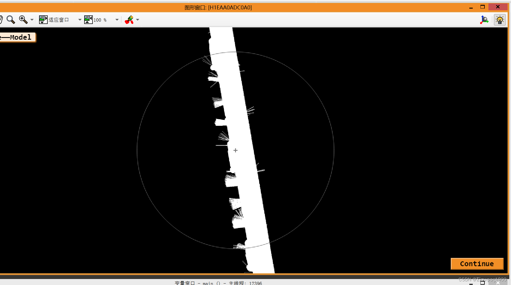
surface_normals_object_model_3d (Model3D, 'mls', 'mls_force_inwards', 'true', ObjectModel3DNormals)
Message_1:='Surface——Model'
visualize_object_model_3d(WindowHandle,ObjectModel3DNormals,[], [], ['point_size','disp_normals'], [12,'true'], Message_1, [], [], PoseOut)
triangulate_object_model_3d (ObjectModel3DNormals, 'greedy', 'greedy_remove_small_surfaces', 200, ObjectModel3DReference, Information)triangulate_object_model_3d (ObjectModel3DNormals, 'greedy', 'greedy_remove_small_surfaces', 200, ObjectModel3DReference, Information)
这个很重要,就是对法向量的进行三维重建
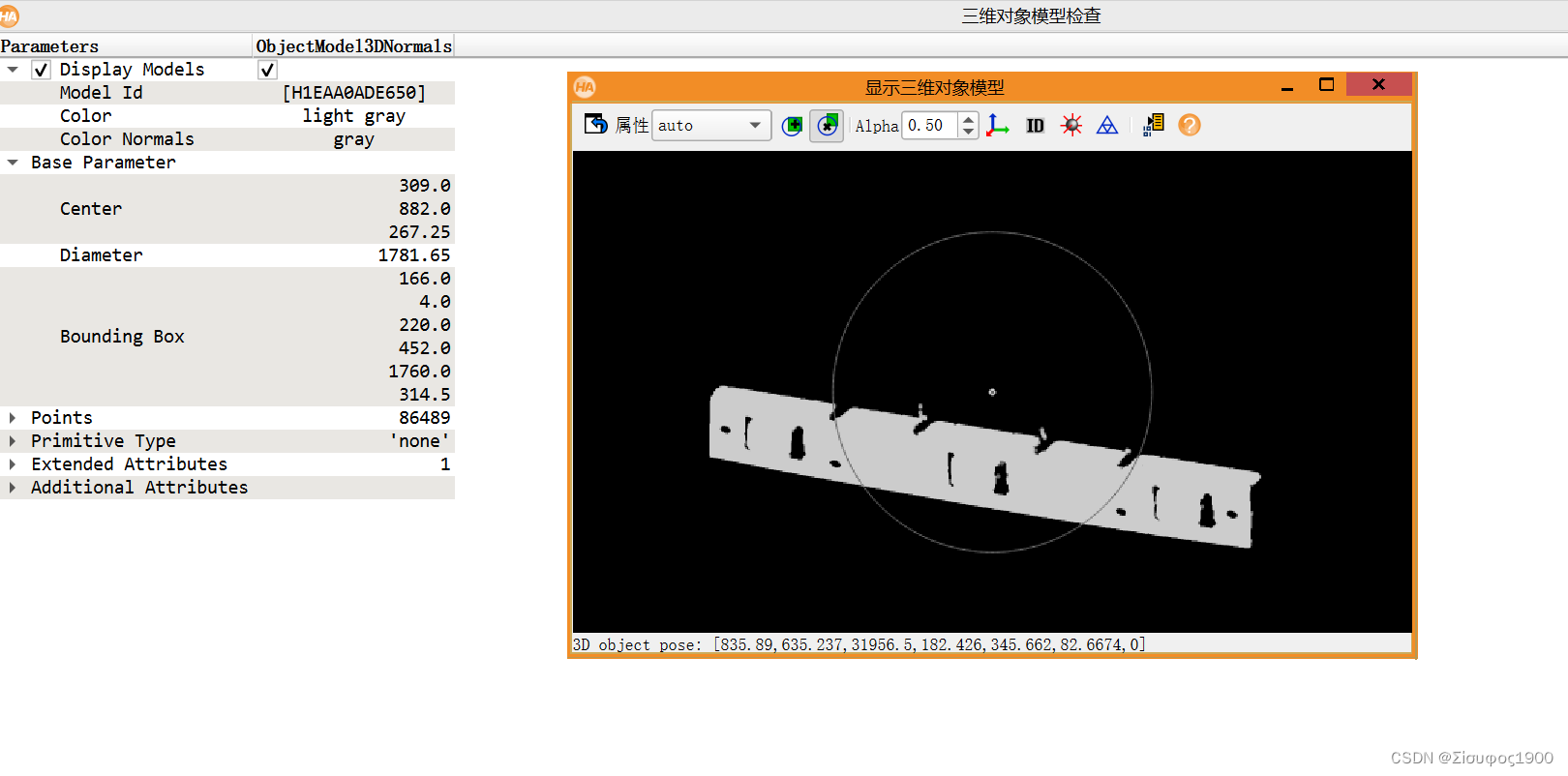
法向量计算的模型
三维重建后的模型:用时1.6s

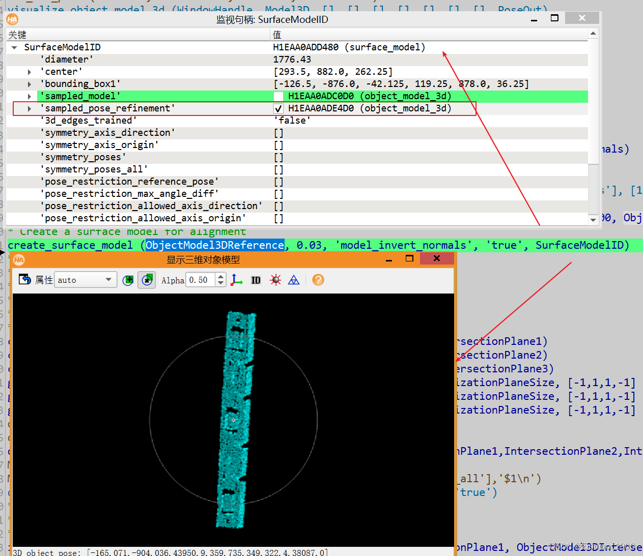
5、生成一个表面模型
* Create a surface model for alignment
create_surface_model (ObjectModel3DReference, 0.03, 'model_invert_normals', 'true', SurfaceModelID)
6、生成切片平面

7、计算切平面与表面模型的交集
intersect_plane_object_model_3d (ObjectModel3DReference, PoseIntersectionPlane3, ObjectModel3DIntersection3)8、投影 :
先做姿态变换
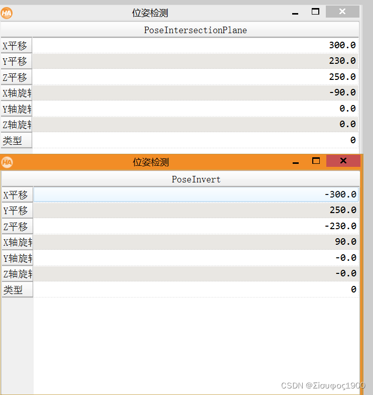
* Determine the intersections and convert them into XLD contours
*
* The inverted intersection plane pose is our projection pose
pose_invert (PoseIntersectionPlane, PoseInvert)
* Make sure, the projection plane lies in front of the camera
* 得到交点模型的直径
get_object_model_3d_params (ObjectModel3DIntersection, 'diameter_axis_aligned_bounding_box', Diameter)
PoseInvert[2] := PoseInvert[2] + Diameter
* Use a parallel projection to achieve the desired scaling (default 1:1)
Scale := 1
gen_cam_par_area_scan_telecentric_division (1.0, 0, 1.0 / Scale, 1.0 / Scale, 0, 0, 512, 512, CamParam)
project_object_model_3d (Intersection, ObjectModel3DIntersection, CamParam, PoseInvert, 'data', 'lines')
return ()
8 、通过轮廓来判断物料是否有损伤,里面用到的全是二维的东西,这里就不说了
    * 分析产品是否有损伤
    analyze_intersection (Intersection1, FittedLines1, OrientationRef, OrientationTolerance, MinDistance1, MaxDistance1, Angle1)
    analyze_intersection (Intersection2, FittedLines2, OrientationRef, OrientationTolerance, MinDistance2, MaxDistance2, Angle2)
    analyze_intersection (Intersection3, FittedLines3, OrientationRef, OrientationTolerance, MinDistance3, MaxDistance3, Angle3)
四、代码显示

* This example shows the inspection of planar intersections of
* 3D objects.  The intersections are derived by intersecting the
* reconstructed 3D object models with suitable planes, using the
* operator intersect_plane_object_model_3d.
*
* The objects, which are metal parts in this example, are
* scanned with an uncalibrated sheet of light setup that returns
* disparities for each scan line. The disparities are
* transformed into a 3D object model. In this example, the
* transformation is based on simple scalings of the three
* dimensions that were chosen such that the reconstructed 3D
* object model is given approximately in mm.
*
* The nominal dimensions and the tolerance limits are derived
* from a reference sample of the metal part. For this,
* intersections derived at predefined positions are analysed.
* Note that if the nominal dimension and tolerance limits should
* be specified numerically, the reconstruction must be done with
* a fully calibrated setup to ensure that the specified values
* are meaningfull with respect to the reconstructed 3D object
* model.
*
* For the inspection, 3D object models of the metal parts are
* reconstructed in the same way as described for the reference
* sample.  With the help of surface based matching, the
* intersection planes, which are defined with respect to the
* reference sample, are aligned with the parts to be inspected.
* The resulting intersections are then analysed to check whether
* the dimensions of the objects to be inspected are within the
* allowed tolerance limits.
*
*
*
* Part 1: Reconstruction of the reference sample and derivation
*         of nominal dimensions and tolerance limits
*
* Set up the sheet of light model
NumDisparityProfiles := 441
read_image (DisparityProfile, 'sheet_of_light/metal_part_1_disparity_line_000')
create_sheet_of_light_model (DisparityProfile, 'calibration', 'offset_scale', SheetOfLightModelID)
* Set the scaling factors for the calibration method 'offset_scale'
* such that the reconstructed 3D object model is given approximately
* in mm
ScaleX := 1
ScaleY := 4
ScaleZ := 0.5
set_sheet_of_light_param (SheetOfLightModelID, 'scale_x', ScaleX)
set_sheet_of_light_param (SheetOfLightModelID, 'scale_y', ScaleY)
set_sheet_of_light_param (SheetOfLightModelID, 'scale_z', ScaleZ)
*
* Define the z coordinate at which the object can be separated from
* the background
MinZ := 220
*
* Initialize display
dev_update_off ()
set_system ('clip_region', 'false')
dev_close_window ()
* 可以理解为视差图  DisparityProfile
get_image_size (DisparityProfile, DisparityProfileWidth, DisparityProfileHeight)
WindowEnlargement := 350
WindowWidth := DisparityProfileWidth + WindowEnlargement
WindowHeight := NumDisparityProfiles
dev_open_window (0, 0, WindowWidth, WindowHeight, 'black', WindowHandle)
dev_set_part (0, 0, WindowHeight - 1, WindowWidth - 1)
get_part (WindowHandle, PartRow1, PartColumn1, PartRow2, PartColumn2)
set_display_font (WindowHandle, 16, 'mono', 'true', 'false')
dev_set_draw ('fill')
*
* Define some visualization parameters
* 定义一个平面的大小
VisualizationPlaneSize := 150
* 生产相机内参
gen_cam_par_area_scan_division (0.01, 0, 6e-6, 6e-6, WindowWidth / 2, WindowHeight / 2, WindowWidth, WindowHeight, VisualizationCamParam)

create_pose (-1550, 680, 5390, 122, 1, 357, 'Rp+T', 'gba', 'point', VisualizationPose)

VisualizationColors := ['magenta','blue','orange']
*
* Create the reference sample by collecting the measured
* disparity profiles in a sheet-of-light model and
* transforming them to a 3D object model
gen_image_const (DisparityImageVis, 'uint2', DisparityProfileWidth, NumDisparityProfiles)
for Index := 0 to NumDisparityProfiles - 1 by 1
    * Add the next disparity profile to the sheet of light model
    read_image (ImageModel, 'sheet_of_light/metal_part_1_disparity_line_' + Index$'03d')
    *设置光片模型的参数
    set_profile_sheet_of_light (ImageModel, SheetOfLightModelID, [])
    * Accumulated profiles for visualization
    * 将光片堆起来并可视化
    get_grayval (ImageModel, gen_tuple_const(DisparityProfileWidth,0), [0:DisparityProfileWidth - 1], Disparities)
    set_grayval (DisparityImageVis, gen_tuple_const(DisparityProfileWidth,Index), [0:DisparityProfileWidth - 1], Disparities)
    if (Index % 5 == 4)
        dev_display (DisparityImageVis)
        Message := 'Disparity image of the reference sample'
        Message[1] := 'Adding disparity profile ' + (Index + 1) + '/' + NumDisparityProfiles
        disp_message (WindowHandle, Message, 'window', 12, 12, 'black', 'true')
    endif
endfor


* Display the disparity image of the reference sample
dev_display (DisparityImageVis)
disp_message (WindowHandle, 'Disparity image of the reference sample', 'window', 12, 12, 'black', 'true')
* Get the 3D reconstruction of the reference sample and eliminate
* the background from the respective 3D object model
* 从光片模型生成一个3d模型
get_sheet_of_light_result_object_model_3d (SheetOfLightModelID, Model3DFull)

get_object_model_3d_params (Model3DFull, 'bounding_box1', BoundingBox1)
MaxZ := BoundingBox1[5]

select_points_object_model_3d (Model3DFull, 'point_coord_z', MinZ, MaxZ, Model3D)

disp_continue_message (WindowHandle, 'black', 'true')
stop ()
*
* Prepare the 3D object model for the intersection with
* the planes and to allow the alignment of the intersection
* planes to the objects to be inspected
dev_clear_window ()
dev_set_part (PartRow1, PartColumn1, PartRow2, PartColumn2)
visualize_object_model_3d (WindowHandle, Model3D, [], [], [], [], [], [], [], PoseOut)
disp_object_model_3d (WindowHandle, Model3D, VisualizationCamParam, VisualizationPose, [], [])

Message := 'Prepare the reference model'
Message[1] := ' - triangulate 3D object model and'
Message[2] := ' - create surface model for alignment'
disp_message (WindowHandle, Message, 'window', 12, 12, 'black', 'true')
* Triangulate the 3D object model

* 表面法向量
surface_normals_object_model_3d (Model3D, 'mls', 'mls_force_inwards', 'true', ObjectModel3DNormals)

Message_1:='Surface——Model'
visualize_object_model_3d(WindowHandle,ObjectModel3DNormals,[], [], ['point_size','disp_normals'], [12,'true'], Message_1, [], [], PoseOut)

triangulate_object_model_3d (ObjectModel3DNormals, 'greedy', 'greedy_remove_small_surfaces', 200, ObjectModel3DReference, Information)
* Create a surface model for alignment
create_surface_model (ObjectModel3DReference, 0.03, 'model_invert_normals', 'true', SurfaceModelID)
*
* Define the intersection planes relative to the reference sample,
* calculate the intersections and derive nominal dimensions and
* tolerance limits from these intersections
*
* Define the intersection planes
create_pose (300, 230, 250, -90, 0, 0, 'Rp+T', 'gba', 'point', PoseIntersectionPlane1)
create_pose (300, 900, 250, -90, 0, 0, 'Rp+T', 'gba', 'point', PoseIntersectionPlane2)
create_pose (300, 1570, 250, -90, 0, 0, 'Rp+T', 'gba', 'point', PoseIntersectionPlane3)
gen_plane_object_model_3d (PoseIntersectionPlane1, [-1,-1,1,1] * VisualizationPlaneSize, [-1,1,1,-1] * VisualizationPlaneSize, IntersectionPlane1)
gen_plane_object_model_3d (PoseIntersectionPlane2, [-1,-1,1,1] * VisualizationPlaneSize, [-1,1,1,-1] * VisualizationPlaneSize, IntersectionPlane2)
gen_plane_object_model_3d (PoseIntersectionPlane3, [-1,-1,1,1] * VisualizationPlaneSize, [-1,1,1,-1] * VisualizationPlaneSize, IntersectionPlane3)
dev_clear_window ()
dev_set_part (PartRow1, PartColumn1, PartRow2, PartColumn2)
disp_object_model_3d (WindowHandle, [ObjectModel3DReference,IntersectionPlane1,IntersectionPlane2,IntersectionPlane3], VisualizationCamParam, VisualizationPose, ['color_1','color_2','color_3','alpha','alpha_0'], [VisualizationColors,0.75,1])
Message := 'Reference sample with predefined intersection planes'
MessageWrapped := regexp_replace(Message + ' ',['(.{0,25})\\s','replace_all'],'$1\n')
disp_message (WindowHandle, MessageWrapped, 'window', 12, 12, 'black', 'true')
*
* Calculate the intersections of the reference sample with the above
* defined planes 求交集
intersect_plane_object_model_3d (ObjectModel3DReference, PoseIntersectionPlane1, ObjectModel3DIntersection1)
intersect_plane_object_model_3d (ObjectModel3DReference, PoseIntersectionPlane2, ObjectModel3DIntersection2)
intersect_plane_object_model_3d (ObjectModel3DReference, PoseIntersectionPlane3, ObjectModel3DIntersection3)
*
* Determine the intersections and convert them into XLD contours
project_object_model_3d_lines_to_contour_xld (Intersection1, PoseIntersectionPlane1, ObjectModel3DIntersection1)
project_object_model_3d_lines_to_contour_xld (Intersection2, PoseIntersectionPlane2, ObjectModel3DIntersection2)
project_object_model_3d_lines_to_contour_xld (Intersection3, PoseIntersectionPlane3, ObjectModel3DIntersection3)
*
* Determine the nominal dimensions and the tolerance limits by
* analysing the measurements from the reference sample
OrientationRef := 20
OrientationTolerance := 20

analyze_intersection (Intersection1, FittedLines1, OrientationRef, OrientationTolerance, MinDistance1, MaxDistance1, Angle1)
analyze_intersection (Intersection2, FittedLines2, OrientationRef, OrientationTolerance, MinDistance2, MaxDistance2, Angle2)
analyze_intersection (Intersection3, FittedLines3, OrientationRef, OrientationTolerance, MinDistance3, MaxDistance3, Angle3)
*
* Visualize the object with the intersection planes and the respective
* intersections and measurement results
hom_mat2d_identity (HomMat2DIdentity)
* Display explanations
Message := 'Intersections with measurement lines'
MessageWrapped := regexp_replace(Message + ' ',['(.{0,20})\\s','replace_all'],'$1\n')
disp_message (WindowHandle, MessageWrapped, 'window', 12, 330, 'black', 'true')
Message := 'Measurement results'
MessageWrapped := regexp_replace(Message + ' ',['(.{0,20})\\s','replace_all'],'$1\n')
disp_message (WindowHandle, MessageWrapped, 'window', 12, 590, 'black', 'true')
* Display first intersection
hom_mat2d_translate (HomMat2DIdentity, 350, 390, HomMat2DTranslate1)
affine_trans_contour_xld (Intersection1, Intersection1Vis, HomMat2DTranslate1)
affine_trans_contour_xld (FittedLines1, FittedLines1Vis, HomMat2DTranslate1)
dev_set_color (VisualizationColors[0])
dev_set_line_width (5)
dev_display (Intersection1Vis)
dev_set_color ('white')
dev_set_line_width (1)
dev_display (FittedLines1Vis)
Message := 'Angle        = ' + Angle1$'.1f' + ' deg'
Message[1] := 'Min Distance = ' + MinDistance1$'.1f' + ' mm'
Message[2] := 'Max Distance = ' + MaxDistance1$'.1f' + ' mm'
disp_message (WindowHandle, Message, 'window', 310, 600, VisualizationColors[0], 'false')
* Display second intersection
hom_mat2d_translate (HomMat2DIdentity, 250, 410, HomMat2DTranslate2)
affine_trans_contour_xld (Intersection2, Intersection2Vis, HomMat2DTranslate2)
affine_trans_contour_xld (FittedLines2, FittedLines2Vis, HomMat2DTranslate2)
dev_set_color (VisualizationColors[1])
dev_set_line_width (5)
dev_display (Intersection2Vis)
dev_set_color ('white')
dev_set_line_width (1)
dev_display (FittedLines2Vis)
Message := 'Angle        = ' + Angle2$'.1f' + ' deg'
Message[1] := 'Min Distance = ' + MinDistance2$'.1f' + ' mm'
Message[2] := 'Max Distance = ' + MaxDistance2$'.1f' + ' mm'
disp_message (WindowHandle, Message, 'window', 210, 600, VisualizationColors[1], 'false')
* Display third intersection
hom_mat2d_translate (HomMat2DIdentity, 150, 430, HomMat2DTranslate3)
affine_trans_contour_xld (Intersection3, Intersection3Vis, HomMat2DTranslate3)
affine_trans_contour_xld (FittedLines3, FittedLines3Vis, HomMat2DTranslate3)
dev_set_color (VisualizationColors[2])
dev_set_line_width (5)
dev_display (Intersection3Vis)
dev_set_color ('white')
dev_set_line_width (1)
dev_display (FittedLines3Vis)
Message := 'Angle        = ' + Angle3$'.1f' + ' deg'
Message[1] := 'Min Distance = ' + MinDistance3$'.1f' + ' mm'
Message[2] := 'Max Distance = ' + MaxDistance3$'.1f' + ' mm'
disp_message (WindowHandle, Message, 'window', 110, 600, VisualizationColors[2], 'false')
disp_continue_message (WindowHandle, 'black', 'true')
stop ()
*
* Define the nominal dimensions and the tolerance limits based
* on the measurements of the reference sample
AngleRef := mean([Angle1,Angle2,Angle3])
MaxAngleDev := 2
MinAngle := AngleRef - MaxAngleDev
MaxAngle := AngleRef + MaxAngleDev
MinDistance := 0.95 * mean([MinDistance1,MinDistance2,MinDistance3])
MaxDistance := 1.05 * mean([MaxDistance1,MaxDistance2,MaxDistance3])
* Display the nominal dimensions and the tolerance limits
dev_clear_window ()
Message := 'Tolerance limits for the angle and the distance of the mounting tabs, derived from the three measurements on the reference sample:'
MessageWrapped := regexp_replace(Message + ' ',['(.{0,75})\\s','replace_all'],'$1\n')
Message := MessageWrapped
Message[1] := ' '
Message[2] := 'Min Angle    = ' + MinAngle$'.1f' + ' deg'
Message[3] := 'Max Angle    = ' + MaxAngle$'.1f' + ' deg'
Message[4] := ' '
Message[5] := 'Min Distance = ' + MinDistance$'.1f' + ' mm'
Message[6] := 'Max Distance = ' + MaxDistance$'.1f' + ' mm'
disp_message (WindowHandle, Message, 'window', 12, 12, 'black', 'true')
disp_continue_message (WindowHandle, 'black', 'true')
stop ()
*
*
* Part 2: Reconstruction of test objects and
*            checking of the respective dimensions
*
* Inspection loop
NumScenes := 4
for SceneIndex := 1 to NumScenes by 1
    dev_clear_window ()
    dev_set_part (PartRow1, PartColumn1, PartRow2, PartColumn2)
    * Reset the dispartities in the sheet of light model; all other settings can be reused
    reset_sheet_of_light_model (SheetOfLightModelID)
    *
    * Create the test object by collecting the measured
    * disparity profiles in a sheet-of-light model and
    * transforming them to a 3D object model
    gen_image_const (DisparityImageVis, 'uint2', DisparityProfileWidth, NumDisparityProfiles)
    for Index := 0 to NumDisparityProfiles - 1 by 1
        * Add the next disparity profile to the sheet of light model
        read_image (ImageSearch, 'sheet_of_light/metal_part_' + (SceneIndex + 1) + '_disparity_line_' + Index$'03d')
        set_profile_sheet_of_light (ImageSearch, SheetOfLightModelID, [])
        * Accumulated profiles for visualization
        get_grayval (ImageSearch, gen_tuple_const(DisparityProfileWidth,0), [0:DisparityProfileWidth - 1], Disparities)
        set_grayval (DisparityImageVis, gen_tuple_const(DisparityProfileWidth,Index), [0:DisparityProfileWidth - 1], Disparities)
        if (Index % 5 == 4 or Index == (NumDisparityProfiles - 1))
            dev_display (DisparityImageVis)
            Message := 'Disparity image of test object ' + SceneIndex
            Message[1] := 'Adding disparity profile ' + (Index + 1) + '/' + NumDisparityProfiles
            disp_message (WindowHandle, Message, 'window', 12, 12, 'black', 'true')
        endif
    endfor
    * Get the 3D reconstruction of the test object and eliminate
    * the background from the respective 3D object model
    get_sheet_of_light_result_object_model_3d (SheetOfLightModelID, Scene3DFull)
    get_object_model_3d_params (Scene3DFull, 'bounding_box1', BoundingBox1)
    MaxZ := BoundingBox1[5]
    select_points_object_model_3d (Scene3DFull, 'point_coord_z', MinZ, MaxZ, Scene3D)
    *
    * Align the intersection planes to the actual position and orientation
    * of the test object and prepare the test object for the intersection
    dev_clear_window ()
    dev_set_part (PartRow1, PartColumn1, PartRow2, PartColumn2)
    disp_object_model_3d (WindowHandle, Scene3D, VisualizationCamParam, VisualizationPose, [], [])
    Message := 'Prepare the 3D object model of the test object'
    Message[1] := ' - perform surface based matching for alignment'
    Message[2] := ' - triangulate 3D object model'
    disp_message (WindowHandle, Message[0], 'window', 12, 12, 'black', 'true')
    *
    * Match the test object with the reference sample.
    * Note that the RelSamplingDistance has been set fairly small.
    * This is necessary because the object has only little 3D variations
    * that can be used by the matching process.
    disp_message (WindowHandle, Message[0:1], 'window', 12, 12, 'black', 'true')
    find_surface_model (SurfaceModelID, Scene3D, 0.005, 0.2, 0, 'false', [], [], Pose, Score, SurfaceMatchingResultID)
    * Align the intersection planes to the test object
    rigid_trans_object_model_3d (IntersectionPlane1, Pose, IntersectionPlane1Aligned)
    rigid_trans_object_model_3d (IntersectionPlane2, Pose, IntersectionPlane2Aligned)
    rigid_trans_object_model_3d (IntersectionPlane3, Pose, IntersectionPlane3Aligned)
    get_object_model_3d_params (IntersectionPlane1Aligned, 'primitive_parameter_pose', IntersectionPlane1AlignedPose)
    get_object_model_3d_params (IntersectionPlane2Aligned, 'primitive_parameter_pose', IntersectionPlane2AlignedPose)
    get_object_model_3d_params (IntersectionPlane3Aligned, 'primitive_parameter_pose', IntersectionPlane3AlignedPose)
    * Triangulate the 3D object model
    disp_message (WindowHandle, Message[0:2], 'window', 12, 12, 'black', 'true')
    triangulate_object_model_3d (Scene3D, 'greedy', [], [], Scene3DTest, Information)
    dev_clear_window ()
    disp_object_model_3d (WindowHandle, [Scene3DTest,IntersectionPlane1Aligned,IntersectionPlane2Aligned,IntersectionPlane3Aligned], VisualizationCamParam, VisualizationPose, ['color_1','color_2','color_3','alpha','alpha_0'], [VisualizationColors,0.75,1])
    Message := 'Test object ' + SceneIndex + ' with aligned intersection planes'
    MessageWrapped := regexp_replace(Message + ' ',['(.{0,25})\\s','replace_all'],'$1\n')
    disp_message (WindowHandle, MessageWrapped, 'window', 12, 12, 'black', 'true')
    *
    * Calculate the intersections of the test object with the respectively
    * aligned planes
    intersect_plane_object_model_3d (Scene3DTest, IntersectionPlane1AlignedPose, ObjectModel3DIntersection1)
    intersect_plane_object_model_3d (Scene3DTest, IntersectionPlane2AlignedPose, ObjectModel3DIntersection2)
    intersect_plane_object_model_3d (Scene3DTest, IntersectionPlane3AlignedPose, ObjectModel3DIntersection3)
    *
    * Determine the intersections and convert them into XLD contours
    project_object_model_3d_lines_to_contour_xld (Intersection1, IntersectionPlane1AlignedPose, ObjectModel3DIntersection1)
    project_object_model_3d_lines_to_contour_xld (Intersection2, IntersectionPlane2AlignedPose, ObjectModel3DIntersection2)
    project_object_model_3d_lines_to_contour_xld (Intersection3, IntersectionPlane3AlignedPose, ObjectModel3DIntersection3)
    *
    * Determine the actual dimensions by analysing the measurements
    * from the test object
    * 分析产品是否有损伤
    analyze_intersection (Intersection1, FittedLines1, OrientationRef, OrientationTolerance, MinDistance1, MaxDistance1, Angle1)
    analyze_intersection (Intersection2, FittedLines2, OrientationRef, OrientationTolerance, MinDistance2, MaxDistance2, Angle2)
    analyze_intersection (Intersection3, FittedLines3, OrientationRef, OrientationTolerance, MinDistance3, MaxDistance3, Angle3)
    *
    * Visualize the object with the intersection planes and the respective
    * intersections and measurement results
    * Display headings
    OverallCheckPassed := true
    Message := 'Intersections with measurement lines'
    MessageWrapped := regexp_replace(Message + ' ',['(.{0,20})\\s','replace_all'],'$1\n')
    disp_message (WindowHandle, MessageWrapped, 'window', 12, 310, 'black', 'true')
    Message := 'Measurement results'
    MessageWrapped := regexp_replace(Message + ' ',['(.{0,20})\\s','replace_all'],'$1\n')
    disp_message (WindowHandle, MessageWrapped, 'window', 12, 590, 'black', 'true')
    * Display first intersection
    affine_trans_contour_xld (Intersection1, Intersection1Vis, HomMat2DTranslate1)
    affine_trans_contour_xld (FittedLines1, FittedLines1Vis, HomMat2DTranslate1)
    dev_set_color (VisualizationColors[0])
    dev_set_line_width (5)
    dev_display (Intersection1Vis)
    dev_set_color ('white')
    dev_set_line_width (1)
    dev_display (FittedLines1Vis)
    Message := 'Angle        = ' + Angle1$'.1f' + ' deg'
    Message[1] := 'Min Distance = ' + MinDistance1$'.1f' + ' mm'
    Message[2] := 'Max Distance = ' + MaxDistance1$'.1f' + ' mm'
    disp_message (WindowHandle, Message, 'window', 310, 600, VisualizationColors[0], 'false')
    ErrorIndicator := gen_tuple_const(3,'OK')
    ErrorIndicatorColor := gen_tuple_const(3,'dim gray')
    if (Angle1 [<] MinAngle or Angle1 [>] MaxAngle)
        ErrorIndicator[0] := 'NOK'
        ErrorIndicatorColor[0] := 'red'
        OverallCheckPassed := false
    endif
    if (MinDistance1 [<] MinDistance)
        ErrorIndicator[1] := 'NOK'
        ErrorIndicatorColor[1] := 'red'
        OverallCheckPassed := false
    endif
    if (MaxDistance1 [>] MaxDistance)
        ErrorIndicator[2] := 'NOK'
        ErrorIndicatorColor[2] := 'red'
        OverallCheckPassed := false
    endif
    disp_message (WindowHandle, ErrorIndicator, 'window', 310, 880, ErrorIndicatorColor, 'false')
    * Display second intersection
    affine_trans_contour_xld (Intersection2, Intersection2Vis, HomMat2DTranslate2)
    affine_trans_contour_xld (FittedLines2, FittedLines2Vis, HomMat2DTranslate2)
    dev_set_color (VisualizationColors[1])
    dev_set_line_width (5)
    dev_display (Intersection2Vis)
    dev_set_color ('white')
    dev_set_line_width (1)
    dev_display (FittedLines2Vis)
    Message := 'Angle        = ' + Angle2$'.1f' + ' deg'
    Message[1] := 'Min Distance = ' + MinDistance2$'.1f' + ' mm'
    Message[2] := 'Max Distance = ' + MaxDistance2$'.1f' + ' mm'
    disp_message (WindowHandle, Message, 'window', 210, 600, VisualizationColors[1], 'false')
    ErrorIndicator := gen_tuple_const(3,'OK')
    ErrorIndicatorColor := gen_tuple_const(3,'dim gray')
    if (Angle2 [<] MinAngle or Angle2 [>] MaxAngle)
        ErrorIndicator[0] := 'NOK'
        ErrorIndicatorColor[0] := 'red'
        OverallCheckPassed := false
    endif
    if (MinDistance2 [<] MinDistance)
        ErrorIndicator[1] := 'NOK'
        ErrorIndicatorColor[1] := 'red'
        OverallCheckPassed := false
    endif
    if (MaxDistance2 [>] MaxDistance)
        ErrorIndicator[2] := 'NOK'
        ErrorIndicatorColor[2] := 'red'
        OverallCheckPassed := false
    endif
    disp_message (WindowHandle, ErrorIndicator, 'window', 210, 880, ErrorIndicatorColor, 'false')
    * Display third intersection
    affine_trans_contour_xld (Intersection3, Intersection3Vis, HomMat2DTranslate3)
    affine_trans_contour_xld (FittedLines3, FittedLines3Vis, HomMat2DTranslate3)
    dev_set_color (VisualizationColors[2])
    dev_set_line_width (5)
    dev_display (Intersection3Vis)
    dev_set_color ('white')
    dev_set_line_width (1)
    dev_display (FittedLines3Vis)
    Message := 'Angle        = ' + Angle3$'.1f' + ' deg'
    Message[1] := 'Min Distance = ' + MinDistance3$'.1f' + ' mm'
    Message[2] := 'Max Distance = ' + MaxDistance3$'.1f' + ' mm'
    disp_message (WindowHandle, Message, 'window', 110, 600, VisualizationColors[2], 'false')
    ErrorIndicator := gen_tuple_const(3,'OK')
    ErrorIndicatorColor := gen_tuple_const(3,'dim gray')
    if (Angle3 [<] MinAngle or Angle3 [>] MaxAngle)
        ErrorIndicator[0] := 'NOK'
        ErrorIndicatorColor[0] := 'red'
        OverallCheckPassed := false
    endif
    if (MinDistance3 [<] MinDistance)
        ErrorIndicator[1] := 'NOK'
        ErrorIndicatorColor[1] := 'red'
        OverallCheckPassed := false
    endif
    if (MaxDistance3 [>] MaxDistance)
        ErrorIndicator[2] := 'NOK'
        ErrorIndicatorColor[2] := 'red'
        OverallCheckPassed := false
    endif
    disp_message (WindowHandle, ErrorIndicator, 'window', 110, 880, ErrorIndicatorColor, 'false')
    * Display overall check result
    if (OverallCheckPassed)
        dev_set_color ('green')
        gen_rectangle1 (Rectangle, 0, WindowWidth - 120, 80, WindowWidth)
        dev_display (Rectangle)
        disp_message (WindowHandle, 'OK', 'window', 30, 900, 'black', 'false')
    else
        dev_set_color ('red')
        gen_rectangle1 (Rectangle, 0, WindowWidth - 120, 80, WindowWidth)
        dev_display (Rectangle)
        disp_message (WindowHandle, 'NOK', 'window', 30, 900, 'white', 'false')
    endif
    if (SceneIndex < NumScenes)
        disp_continue_message (WindowHandle, 'black', 'true')
        stop ()
    endif
endfor