一、简介
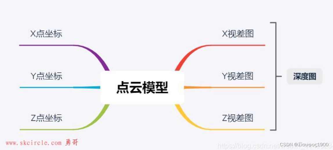
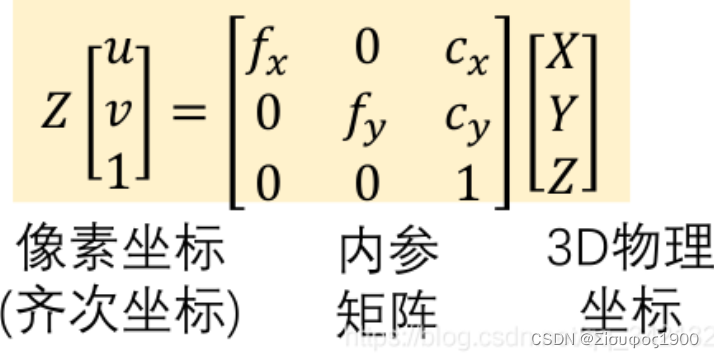
深度图像和 3D 点云互转只涉及相机内参矩阵,其中
- fx,fy 分别为镜头 x,y 方向的焦距(成像平面到镜头的距离)
- cx,cy 分别是光心(镜头中心点在成像平面的投影)在图像坐标系(原点位于图像左上角,水平为 x,垂直为 y)下的坐标。
二、算子介绍
1、auto_threshold 阈值分割
auto_threshold (AerialImage, Regions, 5)
* auto_threshold(Image : Regions : Sigma : )
*根据直方图确定阈值自动全局阈值分割,运行原理,第一,计算灰度直方图。第二,高斯平滑后从直方图提取最小值。第三,根据提取的最小值进行阈值分割。sigma越大提取区域越少。
2、region_to_label 图像转换
*将分割后区域转换为标签图像。
region_to_label (Regions, LabelImage, 'byte', Width, Height)
* region_to_label根据它们的索引(1..n)将输入区域转换成标签图像,即,第一区域被绘成灰度值1,第二区域被绘成灰度值2等。仅使用正灰度值。
第三个参数 :  * 对于'byte'图像,索引以取256的模输入。默认是int2
*Width (input_control)要生成的图像的宽度
*Height (input_control) 要生成的图像的高度
3、gen_image_surface_first_order 使用多项式将创建倾斜的灰色曲面
gen_image_surface_first_order (X, 'real', 0, xishu, 0,  0, 0, Width, Height)
gen_image_surface_first_order (Y, 'real', -xishu, 0, 0, 0, 0, Width, Height)
*  使用一阶多项式创建倾斜的灰色曲面。 (输出图像,类型,垂直方向的参数,水平方向的参数,0阶参数,参考点的行坐标,列坐标,图像的宽高)。

* ImageSurface(r,c) = Alpha(r - Row) +Beta(c - Column) +Gamma
*gen_image_surface_first_order( : ImageSurface : Type, Alpha, Beta, Gamma, Row, Column, Width, Height : )
*ImageSurface (output_object) 新创建的图像矩阵。
*Type (input_control)像素类型  'byte'
*Alpha (input_control) 垂直方向的一阶系数
*Beta (input_control)水平方向上的一阶系数
*Gamma (input_control) 零阶系数
*Row (input_control)曲面参考点的行坐标
*Column (input_control)曲面参考点的列坐标
*Width (input_control) 图像宽度
*Height (input_control)  图像高度
4、 xyz_to_object_model_3d 将3D点从图像转换为3D对象模型
xyz_to_object_model_3d (X, Y, Z, ObjectModel3DID)
*输入:
*X  单通道图像    用三维点的x坐标和三维点ROI区域。
*Y  单通道图像    图像与三维点的y坐标。
*Z 单通道图像    图像与三维点的z坐标。
*输出:3D对象模型的句柄。
5、gen_cam_par_area_scan_division 相机参数
* 生成面阵相机初始参数,参数均为相机已知参数
* 焦距, 畸变因子,
* Sx, Sy为传感器芯片上两个相邻单元之间的水平竖直距离,也就是像素的大小,单位为m/像素
* Cx, Cy为图像原点的行列坐标,单位为像素;)
* 图像宽度
* 图像高度
* CameraParam存储元组
6、select_points_object_model_3d 3D对象模型阀值分割
select_points_object_model_3d (ObjectModel3DID, 'point_coord_z', MinValue, MaxValue, ObjectModel3DIDReduced)
* 第二个参数:
*'point_coord_x':3D 点集的 x 坐标。
*'point_coord_y':
*'point_coord_z':
*
*
*'point_normal_x':3D 点集的 3D 点法线的 x 分量
*'point_normal_y':
*'point_normal_z':
*
*
*'mapping_row':映射行
*'mapping_col':
*
*
*'neighbor_distance':
*'neighbor_distance N':第 N 个最近点的距离。 N 必须是正整数,默认为 25。对于每个点,所有其他点都根据它们的距离排序,并使用第 N 个点的距离。
*'num_neighbors X':最多 X 距离内的邻居数。它可用于移除 3D 对象模型中人口稀少的部分,例如通过平滑 3D 表面之间创建的异常值或点。
*'num_neighbors_fast X':最多 X 距离内的邻居的近似数量。距离使用体素近似,与“num_neighbors”相比,处理速度更快。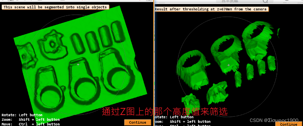
7、connection_object_model_3d 连通分量(2D连通域)
connection_object_model_3d (ObjectModel3DIDReduced, 'distance_3d', 0.010, ObjectModel3DIDConnections)
 *connection_object_model_3d — 确定 3D 对象模型的连接组件.
*'distance_3d': 测试3D点集的点坐标之间的欧几里得距离。对于低于 Value 的任何距离,这些点都被视为已连接
*'angle':比较 3D 对象模型中点的法线之间的角度。如果它们的角距离低于值,则类似的法线被认为是连接的。值以弧度指定,应介于 0 和 pi 之间
*'distance_mapping':映射测量存储在 2D 映射中的 3D 对象模型中的点的像素坐标之间的距离。对 Value 使用大于 1.5 的值,以获取图像中 8 邻域中的连接。
*'mesh':返回与三角形或多边形连接的 3D 对象模型的部分。值被忽略
*'lines':返回由线连接的对象模型的部分。值被忽略。
8、xyz_attrib_to_object_model_3d 生产3D模型
xyz_attrib_to_object_model_3d (X, Y, Z, MultiChannelAttribImage, AttribName, ObjectModel3D)
* *xyz_attrib_to_object_model_3d 将图像 X、Y 和 Z 转换为 3D 对象模型 ObjectModel3D。此外,它将 AttribName 中的点属性设置为 AttribImage 中的值。
*该过程可用于创建使用 RGB 图像设置扩展属性“&red”、“&green”和“&blue”的 3D 对象模型
*AttribImage 可以是多通道图像。属性图像的通道数必须等于元组 AttribName 的大小。此外,图像 X、Y、Z 和 AttribImage 的大小必须相同。
*仅使用 X、Y 和 Z 图像的相交域中的点。 AttribImage 的域被忽略。创建的 3D 对象模型包含点的坐标,以及包含每个 3D 点的原始行和列的 xyz 映射属性。其中一个坐标为无穷大或“非数字”(NaN) 的点将被忽略并且不会添加到 3D 对象模型中。
*
*
*参数
*X  带有 3D 点 X 坐标的图像。
*Y
*Z
*AttribImage 具有属性的(多通道)图像。
*AttribName 属性的名称: ['&red', '&green', '&blue'], '&distance'
*ObjectModel3D
xyz_attrib_to_object_model_3d 的内部逻辑
*
* Consistency checks:
count_obj (AttribImage, Number)
if (Number != 1)
    throw ('The attribute image must be an image array with exactly one object. If you want to set multiple attributes, use a multichannel image.')
endif
*
count_channels (AttribImage, Channels)
if (Channels != |AttribName|)
    throw ('The number of channels of the attribute image (' + Channels + ') must be equal to the number of attribute names (' + |AttribName| + ').')
endif
*
get_image_size (X, WidthX, HeightX)
get_image_size (Y, WidthY, HeightY)
get_image_size (Z, WidthZ, HeightZ)

* 保证三张图片一样大
get_image_size (AttribImage, WidthA, HeightA)
if (WidthX != WidthY or HeightX != HeightY or WidthX != WidthZ or HeightX != HeightZ or WidthX != WidthA or HeightX != HeightA)
    throw ('Image sizes do not match. The size of all input images must be equal.')
endif
*
get_param_info ('set_object_model_3d_attrib_mod', 'AttribName', 'value_list', AvailableAttributes)
*第四个参数
*Slot (input_control): 'assertion', 'cd_type_list.opencl', 'cd_value_list.opencl', 'default_type', 'default_value', 'description', 'mixed_type', 'modified', 'multichannel', 'multivalue', 'sem_type', 'stepmin', 'steprec', 'type_list', 'value_list', 'valuefunction', 'valuemax', 'valuemin', 'valuenumber', 'values'


tuple_regexp_select (AvailableAttributes, 'point_.*', Selection)
tuple_difference (AttribName, Selection, Difference)
**tuple_difference将数组1元素一一和数组2的对比,取出不同部分
tuple_regexp_select (Difference, '^[^&]', InvalidParameters)
if (|InvalidParameters| > 0)
    Exception := 'The following attribute names are invalid: ' + sum(InvalidParameters + ', ') + 'please use a \'&\' prefix for extended attributes, e.g., \'&' + InvalidParameters[0] + '\', or a standard point attribute.'
    throw (Exception)
endif
*
* Get the domain of the images containing the 3D points and get the region all
* three of them share. This is because xyz_to_object_model_3d only uses points
* in the intersecting domains of all three images.
* 求三个图像 的交集
get_domain (X, DomainX)
get_domain (Y, DomainY)
get_domain (Z, DomainZ)

intersection (DomainX, DomainY, RegionIntersectionTmp)
intersection (RegionIntersectionTmp, DomainZ, RegionIntersection)
*
* 将x,y ,z 三个单维度的图片生产一个3D模型
xyz_to_object_model_3d (X, Y, Z, ObjectModel3D)
*
* Loop through all channels and collect the corresponding attribute values
*循环所有通道并收集相应的属性值
AttribValues := []
for Index := 1 to Channels by 1
    access_channel (AttribImage, Channel, Index)
    get_region_points (RegionIntersection, Rows, Columns)
    get_grayval (Channel, Rows, Columns, AttribValuesTmp)
    AttribValues := [AttribValues,AttribValuesTmp]
endfor
*
* Set the attributes
set_object_model_3d_attrib_mod (ObjectModel3D, AttribName, 'points', AttribValues)
return () 

8、get_object_model_3d_params 获得坐标系下所有点Z轴的位置
get_object_model_3d_params (ObjectModel3D, 'point_coord_z', GenParamValue_Z)
* 第二个参数
*'bounding_box1', 'center', 'diameter_axis_aligned_bounding_box', 'extended_attribute_names',
*'has_distance_computation_data', 'has_extended_attribute', 'has_lines', 'has_point_normals',
*'has_points', 'has_polygons', 'has_primitive_data', 'has_primitive_rms', 'has_segmentation_data',
*'has_shape_based_matching_3d_data', 'has_surface_based_matching_data', 'has_triangles', 'has_xyz_mapping',
*'lines', 'mapping_col', 'mapping_row', 'num_extended_attribute', 'num_lines', 'num_points', 'num_polygons',
*'num_primitive_parameter_extension', 'num_triangles', 'point_coord_x', 'point_coord_y', 'point_coord_z',
*'point_normal_x', 'point_normal_y', 'point_normal_z', 'polygons', 'primitive_parameter',
*'primitive_parameter_extension',
*'primitive_parameter_pose', 'primitive_pose', 'primitive_rms', 'primitive_type',
*'reference_point', 'triangles'
其他使用后面慢慢补充
10、get_param_info 查询关于操作get_param_info的空档的在线信息
*第四个参数
*Slot (input_control): 'assertion', 'cd_type_list.opencl', 'cd_value_list.opencl',
 'default_type', 'default_value', 'description', 'mixed_type', 'modified',
 'multichannel', 'multivalue', 'sem_type', 'stepmin', 'steprec', 'type_list',
 'value_list', 'valuefunction', 'valuemax', 'valuemin', 'valuenumber', 'values'

三、代码演示
案例一
dev_update_off ()
dev_close_window ()
* 1、加载X,Y, z数据,缩放到米,并生成一个3D对象模型
ImagePath := 'time_of_flight/'
read_image (Image, ImagePath + 'engine_cover_xyz_01')
* 缩放图像的灰度值
* 将图像放大一个给定的倍数
scale_image (Image, Image, .001, .0)
zoom_image_factor (Image, Image, 2, 2, 'constant')
get_image_size (Image, Width2, Height2)
decompose3 (Image, X, Y, Z)// 吧一张图片 分割成三个通道的图像,
xyz_to_object_model_3d (X, Y, Z, ObjectModel3DID)
*输入:
*X 单通道图像 用三维点的x坐标和三维点ROI区域。
*Y 单通道图像 图像与三维点的y坐标。
*Z 单通道图像 图像与三维点的z坐标。
*输出:3D对象模型的句柄。
* 2、计算模型的网格(Delaunay三角测量)
* 为'segmentation',准备一个3D对象模型(如果要对同一操作多次使用3D对象模型,这样做会更快)
prepare_object_model_3d (ObjectModel3DID, 'segmentation', 'true', [], [])
*
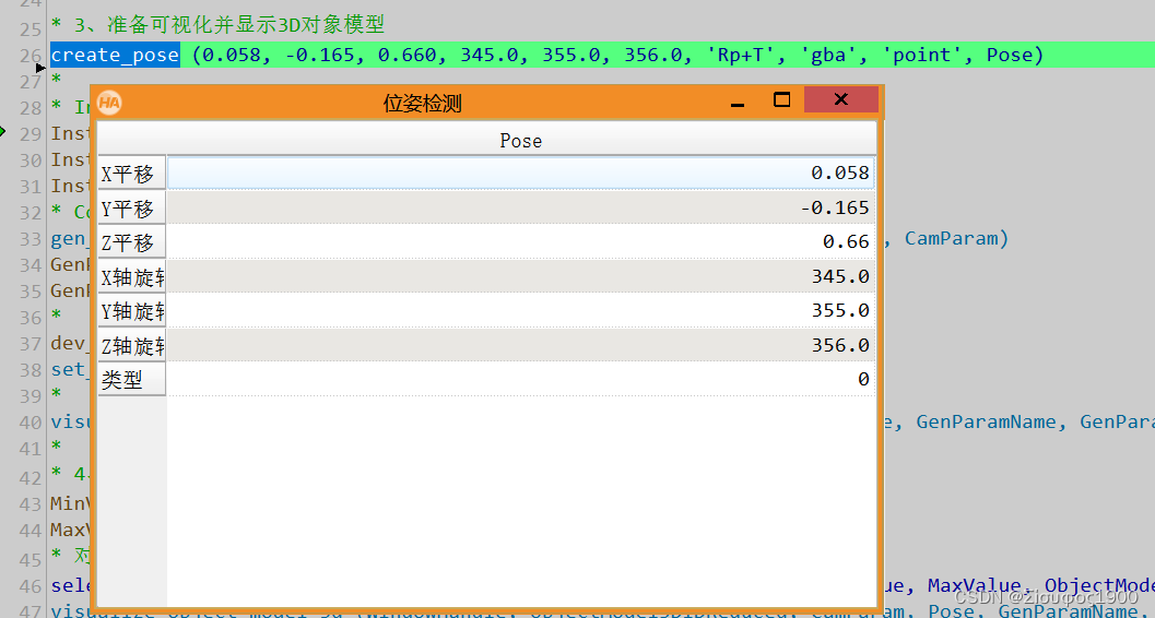
* 3、准备可视化并显示3D对象模型
create_pose (0.058, -0.165, 0.660, 345.0, 355.0, 356.0, 'Rp+T', 'gba', 'point', Pose)
*
* Instructions for visualize_object_model_3d
Instructions[0] := 'Rotate: Left button'
Instructions[1] := 'Zoom: Shift + left button'
Instructions[2] := 'Move: Ctrl + left button'
* Configuration
gen_cam_par_area_scan_division (0.01, 0, 7e-6, 7e-6, 352, 288, 710, 576, CamParam)
* 生成面阵相机初始参数,参数均为相机已知参数
* 焦距, 畸变因子,
* Sx, Sy为传感器芯片上两个相邻单元之间的水平竖直距离,也就是像素的大小,单位为m/像素
* Cx, Cy为图像原点的行列坐标,单位为像素;)
* 图像宽度
* 图像高度
* CameraParam存储元组
GenParamName := ['color','disp_pose','alpha']
GenParamValue := ['green','false',0.8]
*
dev_open_window (0, 0, 710, 576, 'black', WindowHandle)
set_display_font (WindowHandle, 16, 'mono', 'true', 'false')
*
visualize_object_model_3d (WindowHandle, ObjectModel3DID, CamParam, Pose, GenParamName, GenParamValue, 'This scene will be segmented into single objects', [], Instructions, Pose)
*
* 4、阈值三维对象模型
MinValue := 0.500
MaxValue := 0.670
* 对3D对象模型应用阈值
select_points_object_model_3d (ObjectModel3DID, 'point_coord_z', MinValue, MaxValue, ObjectModel3DIDReduced)
* 第二个参数:
*'point_coord_x':3D 点集的 x 坐标。
*'point_coord_y':
*'point_coord_z':
*
*
*'point_normal_x':3D 点集的 3D 点法线的 x 分量
*'point_normal_y':
*'point_normal_z':
*
*
*'mapping_row':映射行
*'mapping_col':
*
*
*'neighbor_distance':
*'neighbor_distance N':第 N 个最近点的距离。 N 必须是正整数,默认为 25。对于每个点,所有其他点都根据它们的距离排序,并使用第 N 个点的距离。
*'num_neighbors X':最多 X 距离内的邻居数。它可用于移除 3D 对象模型中人口稀少的部分,例如通过平滑 3D 表面之间创建的异常值或点。
*'num_neighbors_fast X':最多 X 距离内的邻居的近似数量。距离使用体素近似,与“num_neighbors”相比,处理速度更快。
visualize_object_model_3d (WindowHandle, ObjectModel3DIDReduced, CamParam, Pose, GenParamName, GenParamValue, 'Result after thresholding at z=' + (MaxValue * 1e3)$'.3' + 'mm from the camera', [], Instructions, Pose)
*
* Calculate the connected components and the volume and diameter
* of each of the resulting object
* 5、计算连接分量和每个结果对象的体积和直径
GenParamName[0] := 'colored'
GenParamValue[0] := 12
* 1)确定3D对象模型的连通分量
* 2)计算三维物体模型相对于平面[0,0,MaxValue,0,0,0,0]的体积 Volume
* 3)计算3D对象模型的最大直径 Diameter
connection_object_model_3d (ObjectModel3DIDReduced, 'distance_3d', 0.010, ObjectModel3DIDConnections)
*connection_object_model_3d — 确定 3D 对象模型的连接组件.
*'distance_3d': 测试3D点集的点坐标之间的欧几里得距离。对于低于 Value 的任何距离,这些点都被视为已连接
*'angle':比较 3D 对象模型中点的法线之间的角度。如果它们的角距离低于值,则类似的法线被认为是连接的。值以弧度指定,应介于 0 和 pi 之间
*'distance_mapping':映射测量存储在 2D 映射中的 3D 对象模型中的点的像素坐标之间的距离。对 Value 使用大于 1.5 的值,以获取图像中 8 邻域中的连接。
*'mesh':返回与三角形或多边形连接的 3D 对象模型的部分。值被忽略
*'lines':返回由线连接的对象模型的部分。值被忽略。
volume_object_model_3d_relative_to_plane (ObjectModel3DIDConnections, [0,0,MaxValue,0,0,0,0], 'signed', 'true', Volume)
*volume_object_model_3d_relative_to_plane 计算 3D 对象模型相对于平面的体积
*如果平面和物体之间的距离很大(大约距离 > 物体直径的 10000 倍),体积的计算可能在数值上不稳定
*
*Plane pose
*Mode 组合位于参考平面上方和下方的体积的方法。
*
*List of values: 'negative', 'positive', 'signed', 'unsigned'
*
*Default value: 'true'
*List of values: 'false', 'true'
*
*Number of elements: Volume
max_diameter_object_model_3d (ObjectModel3DIDConnections, Diameter)
*
* 6、显示结果
dev_open_window (0, 720, 400, 576, 'black', WindowHandle1)
set_display_font (WindowHandle1, 14, 'mono', 'true', 'false')
Indices := [0:|ObjectModel3DIDConnections| - 1]
disp_message (WindowHandle1, ['Features of the connected components:',' ',' '], 'window', 12, 12, 'white', 'false')
ResultMessage := ' # Max. diameter Volume'
Sequence := [0:|ObjectModel3DIDConnections| - 1]
ResultMessage := [ResultMessage,Sequence$' 3' + ' ' + (Diameter * 1e3)$'7.1f' + ' mm ' + (Volume * 1e3)$'7.3f' + ' dm³']
disp_message (WindowHandle1, ResultMessage, 'window', 50, 12, 'white', 'false')
dev_set_window (WindowHandle)
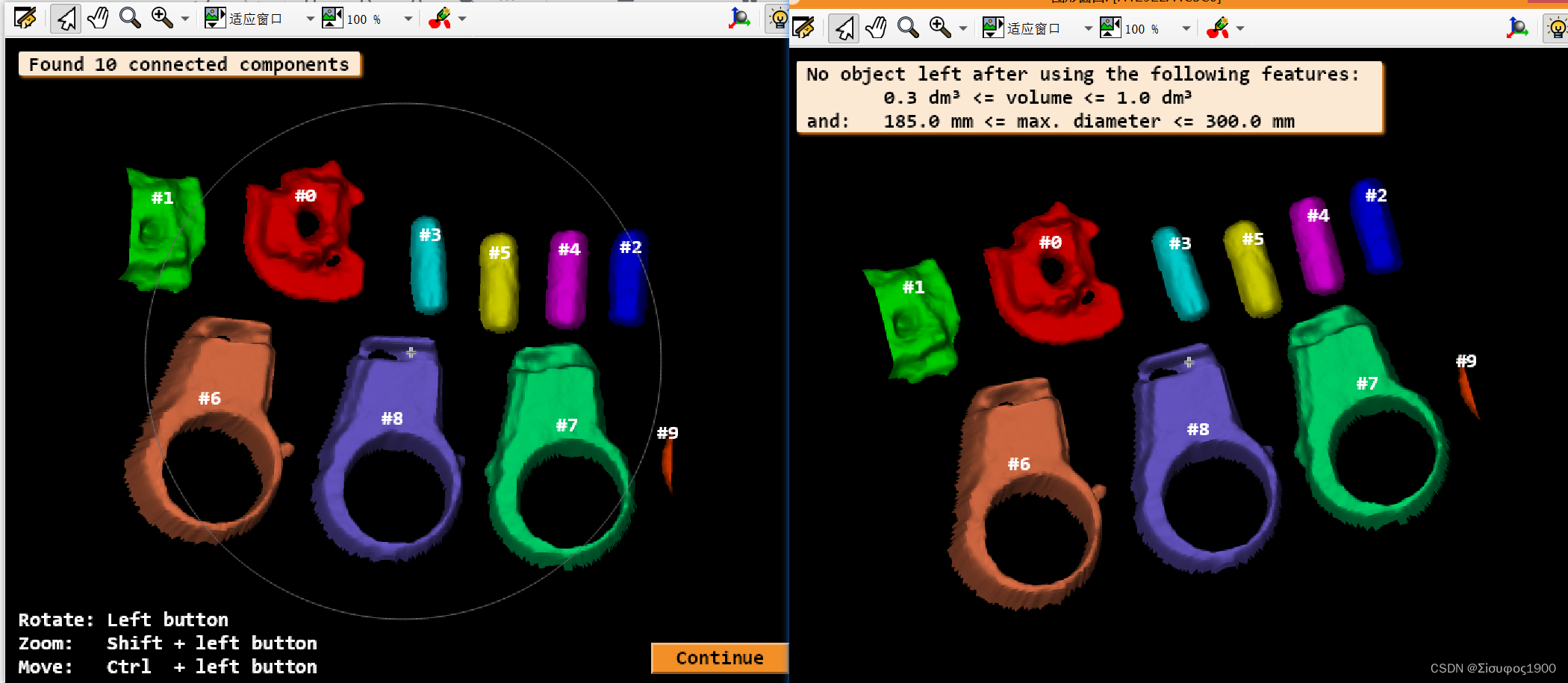
visualize_object_model_3d (WindowHandle, ObjectModel3DIDConnections, CamParam, Pose, GenParamName, GenParamValue, 'Found ' + |ObjectModel3DIDConnections| + ' connected components', '#' + Indices, Instructions, Pose)
*
* 7、根据组件的体积和最大直径选择组件
*
MinVolume := 0.35e-003
MaxVolume := 1.0e-003
MinDiameter := 185.0e-003
MaxDiameter := 300.0e-003
***** 8、注意:
* select_object_model_3d 使用平面[0,0,0,0,0,0]进行体积计算!
* 因此,我们必须转换3d对象模型,以便参考平面(如前面对volume_object_model_3d_relative_to_plane的调用中定义的那样)与默认平面重合。
*
* 1)生成三维变换的齐次变换矩阵
* 2)增加平移变换
* 3)求齐次三维变换矩阵的逆
hom_mat3d_identity (HomMat3DIdentity)
hom_mat3d_translate (HomMat3DIdentity, 0, 0, -MaxValue, HomMat3DTranslation)
hom_mat3d_invert (HomMat3DTranslation, HomMat3DInvert)
affine_trans_object_model_3d (ObjectModel3DIDConnections,HomMat3DInvert, ObjectModel3DTranslated)
* 4)为每个部分设置标签
for Index := 0 to |ObjectModel3DIDConnections| - 1 by 1
set_object_model_3d_attrib_mod (ObjectModel3DTranslated[Index], '&Index', [], Index)
endfor
* 5)再次计算三维物体模型相对于平面[0,0,0,0,0,0,0]的体积 Volume1
volume_object_model_3d_relative_to_plane (ObjectModel3DTranslated, [0,0,0,0,0,0,0], 'signed', 'true', Volume1)
* 6)从一组三维对象模型中选择三维对象模型('volume','diameter_object')
select_object_model_3d (ObjectModel3DTranslated, ['volume','diameter_object'], 'and', [MinVolume,MinDiameter], [MaxVolume,MaxDiameter], ObjectModel3DSelected)
*
Title := ['Parts selected by using the following features: ',' ' + (MinVolume * 1e3)$'3.1f' + ' dm³ <= volume <= ' + (MaxVolume * 1e3)$'3.1f' + ' dm³','and: ' + (MinDiameter * 1e3)$'.1f' + ' mm <= max. diameter <= ' + (MaxDiameter * 1e3)$'.1f' + ' mm']
* 创建一个标签
Label := []
for Index := 0 to |ObjectModel3DSelected| - 1 by 1
get_object_model_3d_params (ObjectModel3DSelected[Index], '&Index', FormerIndex)
Label := [Label,'#' + FormerIndex]
endfor
*
if (|ObjectModel3DSelected| > 1)
visualize_object_model_3d (WindowHandle, ObjectModel3DSelected, CamParam, [], GenParamName, GenParamValue, Title, Label, Instructions, Pose)
else
Message := 'No object left after using the following features: '
Message[1] := ' ' + (MinVolume * 1e3)$'3.1f' + ' dm³ <= volume <= ' + (MaxVolume * 1e3)$'3.1f' + ' dm³'
Message[2] := 'and: ' + (MinDiameter * 1e3)$'.1f' + ' mm <= max. diameter <= ' + (MaxDiameter * 1e3)$'.1f' + ' mm'
disp_message (WindowHandle, Message, 'window', 12, 12, 'black', 'true')
endif
*
* Clear the 3d object models
dev_set_window (WindowHandle1)
dev_close_window ()
clear_object_model_3d ([ObjectModel3DID,ObjectModel3DIDReduced,ObjectModel3DSelected,ObjectModel3DTranslated,ObjectModel3DIDConnections])

案例二
* 初始化界面
dev_update_off ()
dev_close_window ()
*
* 读取Z图,即为深度图
read_image (Z, 'mreut_dgm_2.0.tif')
get_image_size (Z, Width, Height)
*
* 读取灰度图,将其灰度值作为属性添加到3D模型中。
read_image (AerialImage, 'mreut4_3.png')
*
* 用灰度图生成标签图像,采用的方法很简单,只做展示用。
* 自适应的阈值处理方法,将图像分为3个对象,用红蓝绿三种颜色表示。参数4表示高斯平滑的核的大小。如下图所示。
auto_threshold (AerialImage, Regions, 5)
* auto_threshold(Image : Regions : Sigma : )
*根据直方图确定阈值自动全局阈值分割,运行原理,第一,计算灰度直方图。第二,高斯平滑后从直方图提取最小值。第三,根据提取的最小值进行阈值分割。sigma越大提取区域越少。


*将分割后区域转换为标签图像。
region_to_label (Regions, LabelImage, 'byte', Width, Height)
* region_to_label根据它们的索引(1..n)将输入区域转换成标签图像,即,第一区域被绘成灰度值1,第二区域被绘成灰度值2等。仅使用正灰度值。 对于'byte'图像,索引以取256的模输入。

* 将灰度图和标签图像合并为1个2通道复合图像。
compose2 (AerialImage, LabelImage, MultiChannelAttribImage)
*
* 在常规网格中创建包含X和Y坐标的灰度渐变图像。
xishu := 2.0  // Alpha 和 Beta

gen_image_surface_first_order (X, 'real', 0, xishu, 0,  0, 0, Width, Height)
gen_image_surface_first_order (Y, 'real', -xishu, 0, 0, 0, 0, Width, Height)
*  使用一阶多项式创建倾斜的灰色曲面。 (输出图像,类型,垂直方向的参数,水平方向的参数,0阶参数,参考点的行坐标,列坐标,图像的宽高)。

* ImageSurface(r,c) = Alpha(r - Row) +Beta(c - Column) +Gamma
*gen_image_surface_first_order( : ImageSurface : Type, Alpha, Beta, Gamma, Row, Column, Width, Height : )
*ImageSurface (output_object) 新创建的图像矩阵。
*Type (input_control)像素类型  'byte'
*Alpha (input_control) 垂直方向的一阶系数
*Beta (input_control)水平方向上的一阶系数
*Gamma (input_control) 零阶系数
*Row (input_control)曲面参考点的行坐标
*Column (input_control)曲面参考点的列坐标
*Width (input_control) 图像宽度
*Height (input_control)  图像高度。


* =======================================================到此X Y Z的图像已经准备好了==============================================
*
* 创建3D模型
* 属性名
AttribName := ['&gray','&terrain']
* 该算子将包含3D点的X、Y和Z坐标的图像三元组转换为3D对象模型。
* 从上面的程序可以看出,XY图像为与Z图同样大小的灰度渐变图像,MultiChannelAttribImage为两通道的属性图像,包含灰度图像和分割后的标签图像。
* 其中MultiChannelAttribImage的图像通道必须和AttribName的维度大小相同。
* 此时生成的为点云,下面用三角法生成三维图像。
*xyz_to_object_model_3d (Y, Y, Y, ObjectModel3D1)
xyz_attrib_to_object_model_3d (X, Y, Z, MultiChannelAttribImage, AttribName, ObjectModel3D)
* *xyz_attrib_to_object_model_3d 将图像 X、Y 和 Z 转换为 3D 对象模型 ObjectModel3D。此外,它将 AttribName 中的点属性设置为 AttribImage 中的值。
*该过程可用于创建使用 RGB 图像设置扩展属性“&red”、“&green”和“&blue”的 3D 对象模型
*AttribImage 可以是多通道图像。属性图像的通道数必须等于元组 AttribName 的大小。此外,图像 X、Y、Z 和 AttribImage 的大小必须相同。
*仅使用 X、Y 和 Z 图像的相交域中的点。 AttribImage 的域被忽略。创建的 3D 对象模型包含点的坐标,以及包含每个 3D 点的原始行和列的 xyz 映射属性。其中一个坐标为无穷大或“非数字”(NaN) 的点将被忽略并且不会添加到 3D 对象模型中。
*
*
*参数
*X  带有 3D 点 X 坐标的图像。
*Y
*Z
*AttribImage 具有属性的(多通道)图像。
*AttribName 属性的名称: ['&red', '&green', '&blue'], '&distance'
*ObjectModel3D


* Display results
* 设置窗口1的属性,显示“地形类型”
dev_open_window (Height / 2, 0, Width / 2, Height / 2, 'black', WindowHandle1)
dev_set_part (0, 0, Height - 1, Width - 1)
set_display_font (WindowHandle1, 16, 'mono', 'true', 'false')
dev_set_color (['red','green','blue'])
dev_set_draw ('fill')
dev_display (Regions)
disp_message (WindowHandle1, 'Terrain types', 'window', 12, 12, 'black', 'true')
* 设置窗口2的属性,显示“鸟瞰图”
dev_open_window (0, 0, Width / 2, Height / 2, 'black', WindowHandle2)
set_display_font (WindowHandle2, 16, 'mono', 'true', 'false')
dev_display (AerialImage)
disp_message (WindowHandle2, 'Aerial image', 'window', 12, 12, 'black', 'true')
* 设置窗口3的属性,显示“Z图”
dev_open_window (0, Width / 2 + 8, Width, Height, 'gray', WindowHandle3)
set_display_font (WindowHandle3, 16, 'mono', 'true', 'false')
dev_display (Z)
disp_message (WindowHandle3, 'Digital surface model', 'window', 12, 12, 'black', 'true')
disp_continue_message (WindowHandle3, 'black', 'true')
stop ()
*
* 对对象模型进行快速的三角测量,以便更好地进行可视化。
* 该算子通过三角法将点云重建为三维模型。
prepare_object_model_3d (ObjectModel3D, 'segmentation', 'true', [], [])
* 交互式地可视化3d对象模型
* 创建3D模型的位姿(平移量,旋转量,平移旋转的顺序,旋转值的意义,视图转换,位姿)
create_pose (-620, -85, 17000, 135, 2, 10, 'Rp+T', 'gba', 'point', Pose)
Instructions := 'Rotate: Left button'
Instructions[1] := 'Zoom: Shift + left button'
Instructions[2] := 'Move: Ctrl + left button'
*显示3D模型
visualize_object_model_3d (WindowHandle3, ObjectModel3D, [], Pose, ['color_attrib','color_attrib_start','color_attrib_end'], ['&gray',0,255], ['Created 3D model','Attribute used for visualization: \'&gray\''], [], Instructions, PoseOut)
visualize_object_model_3d (WindowHandle3, ObjectModel3D, [], PoseOut, ['color_attrib','lut'], ['&terrain','color1'], ['Created 3D model','Attribute used for visualization: \'&terrain\''], [], Instructions, PoseOut)
disp_end_of_program_message (WindowHandle3, 'black', 'true')
案例三
*1打开3D传感器 smartray ,之前接触过这个德国的产品,75  95  150g 以及200 系列的
open_framegrabber ('GenICamTL', 0, 0, 0, 0, 0, 0, 'progressive', -1, 'default', -1, 'false', 'default', 'default', 0, -1, AcqHandle)
*设置延时
set_framegrabber_param (AcqHandle, 'grab_timeout', 10000)
*加载型号
get_framegrabber_param (AcqHandle, 'Parameter_Set_values', ParameterSetValues)
tuple_regexp_select (ParameterSetValues, '.*_3D_Repeat_Snapshot', ParameterSet)
set_framegrabber_param (AcqHandle, 'Parameter_Set', ParameterSet)
*设置标定数据
set_framegrabber_param (AcqHandle, 'Activate_Calibration', true)
*可以获得中间结果
get_framegrabber_param (AcqHandle, 'Width', Width)
get_framegrabber_param (AcqHandle, 'Height', Height)
get_framegrabber_param (AcqHandle, 'Number_of_Profiles_to_Capture', NumberOfZILCaptured)
get_framegrabber_param (AcqHandle, 'ZMap_Lateral_Resolution', ZILLatRes)
get_framegrabber_param (AcqHandle, 'ZMap_Vertical_Resolution', ZILVerRes)
*初始化传感器
grab_image_start (AcqHandle, -1)
*抓取深度图(Z-map)
grab_image_async (PointCloudZ, AcqHandle, -1)
*图像大小
crop_rectangle1 (PointCloudZ, ZMap, 0, 0, NumberOfZILCaptured - 1, Width - 1)


*得到x,y图
TransportRate := 0.1628 // 分辨率  运动方向(方向)和 x方向

*x图
gen_image_surface_first_order (PointCloudX, 'real', TransportRate, 0, 0, NumberOfZILCaptured / 2, Width / 2, Width, NumberOfZILCaptured)
*  使用一阶多项式创建倾斜的灰色曲面。 (输出图像,类型,垂直方向的参数,水平方向的参数,0阶参数,参考点的行坐标,列坐标,图像的宽高)。

* ImageSurface(r,c) = Alpha(r - Row) +Beta(c - Column) +Gamma
*gen_image_surface_first_order( : ImageSurface : Type, Alpha, Beta, Gamma, Row, Column, Width, Height : )
*ImageSurface (output_object) 新创建的图像矩阵。
*Type (input_control)像素类型  'byte'
*Alpha (input_control) 垂直方向的一阶系数
*Beta (input_control)水平方向上的一阶系数
*Gamma (input_control) 零阶系数
*Row (input_control)曲面参考点的行坐标
*Column (input_control)曲面参考点的列坐标
*Width (input_control) 图像宽度
*Height (input_control)  图像高度。

*y图
gen_image_surface_first_order (ImageYVal, 'real', 0, ZILLatRes, 0, NumberOfZILCaptured / 2, Width / 2, Width, NumberOfZILCaptured)
*-----------------------------------------------------------------------------------------------
*转换下数据类型
threshold (ZMap, RegionValidity, 0, 65535)
    * Z-coordinate: Height information between sensor and the scanned part (in millimeters).
reduce_domain (ZMap, RegionValidity, ImageMeasureValid)
convert_image_type (ImageMeasureValid, ImageMeasureReal, 'real')
get_image_size (ImageMeasureReal, zMap_Width, zMap_Height)
gen_image_const (PointCloudZ, 'real', zMap_Width, zMap_Height)
threshold (ImageMeasureReal, Region_Valid, 1, 9999999)
tuple_pow (2, 15, hv_offset)
*PointCloudZ=ImageMeasureReal*ZILVerRes-hv_offset * ZILVerRes
*PointCloudZ=(ImageMeasureReal-hv_offset) * ZILVerRes
scale_image (ImageMeasureReal, PointCloudZ, ZILVerRes, -hv_offset * ZILVerRes)
reduce_domain (PointCloudZ, Region_Valid, PointCloudZ)
*-----------------------------------------------------------------------------------------------

*生成3D点云模型
* gen_object_model_3d_from_points (hv_offset, hv_offset, hv_offset, ObjectModel3D1) 这个也是生成点云模型,但是这个是x,y,z 的坐标来生成点云模型
*   +++++++++++++++++++++++++++++++++++++++++++++++++++++++++++++
* 这个是我们已经知道xyz的图像生成点云模型
xyz_to_object_model_3d (PointCloudX, ImageYVal, PointCloudZ, ObjectModel3D)
* 该算子将包含3D点的X、Y和Z坐标的图像三元组转换为3D对象模型。
* 从上面的程序可以看出,XY图像为与Z图同样大小的灰度渐变图像,MultiChannelAttribImage为两通道的属性图像,包含灰度图像和分割后的标签图像。
* 其中MultiChannelAttribImage的图像通道必须和AttribName的维度大小相同。
* 此时生成的为点云,下面用三角法生成三维图像。
* +++++++++++++++++++++++++++++++++++++++++++++++++++++++++++++++++++++++++++++++++
triangulate_object_model_3d (ObjectModel3D, 'greedy', [], [], TriangulatedObjectModel3D, Information)
dev_open_window (0, 0, 512, 512, 'black', WindowHandle)
visualize_object_model_3d (WindowHandle, TriangulatedObjectModel3D, [], [], ['lut','color_attrib'], ['color1','coord_z'], 'ObjectModel3D', [], [], PoseOut)
gen_rectangle1 (ROI_0, -0.402344, 747.698, 99.207, 1153.76)
intensity (ROI_0, PointCloudZ, Mean, Deviation)
height:=Mean
visualize_object_model_3d (WindowHandle, TriangulatedObjectModel3D, [], [], ['lut','color_attrib','disp_pose'], ['color1','coord_z','true'], '台阶高度'+height, [], [], PoseOut)


   CutPlanePose[0]:=0
   CutPlanePose[1]:=0
   CutPlanePose[2]:=0
   CutPlanePose[3]:=0
   CutPlanePose[4]:=90
   CutPlanePose[5]:=0
   CutPlanePose[6]:=0
   gen_plane_object_model_3d (CutPlanePose, [-1,-1,1,1] * 20, [-1,1,1,-1] * 20, IntersectionPlane)
   visualize_object_model_3d (WindowHandle, [TriangulatedObjectModel3D,IntersectionPlane], [], [], ['color_0','color_1','disp_pose'], ['blue','red','true'], [], [], [], PoseOut1)
   intersect_plane_object_model_3d (TriangulatedObjectModel3D, CutPlanePose, ObjectModel3DIntersection)
*    visualize_object_model_3d (WindowHandle, ObjectModel3DIntersection, [], [], [], [], [], [], [], PoseOut2)
   *4变换到二维XLD
   pose_invert (CutPlanePose, PoseInvert)
   *确定投影平面在前面
   get_object_model_3d_params (ObjectModel3DIntersection, 'diameter_axis_aligned_bounding_box', Diameter)
   PoseInvert[2] := PoseInvert[2] +Diameter
 * 用平行于投影平面的相机(1:1的比例)
   Scale:=1
   CamParam := [0,0,1.0 / Scale,1.0 / Scale,0,0,500,500]
   *求投影xld
   project_object_model_3d (IntersectionXld, ObjectModel3DIntersection, CamParam, PoseInvert, 'data', 'lines')