This exercise will improve LED program
1. Modular
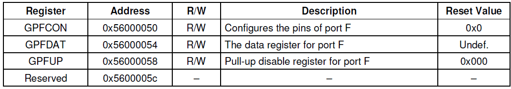
First, the program will be modular division, will register the relevant information in s3c2440.h , the subsequent use to register will continue to add other functions, and thus gradually improve the header file. Existing LED module while module, which is provided independently of a document, and the main file to call these modules provide a mechanism to achieve the desired functionality. (Startup file there is no difference, it is not listed.)
s3c2440.h
---------------------------------------
#ifndef __S3C2440_H
#define __S3C2440_H

#include <stdint.h>

/* GPIO */
#define GPFCON	(*((volatile uint32_t*)0x56000050))
#define GPFDAT	(*((volatile uint32_t*)0x56000054))

#endif
led.h
----------------------------------
#ifndef __LED_H
#define __LED_H

#include <stdint.h>

#define kLed1  4
#define kLed2  5
#define kLed3  6


void LedInitAll(void);
void SingleLedInit(const uint8_t ledn);
void SingleLedON(const uint8_t ledn);
void SingleLedOFF(const uint8_t ledn);

#endif
led.c
--------------------------------------
#include "led.h"

#include "s3c2440.h"

void LedInitAll(void)
{
	SingleLedInit(kLed1);
	SingleLedInit(kLed2);
	SingleLedInit(kLed3);
	SingleLedOFF(kLed1);
	SingleLedOFF(kLed2);
	SingleLedOFF(kLed3);
}


/* init the led gpio as a output pin */
void SingleLedInit(const uint8_t ledn)
{
	GPFCON &= ~(3 << ledn * 2);
	GPFCON |= (1 << ledn * 2);
}

void SingleLedON(const uint8_t ledn)
{
	GPFDAT &=~(1 << ledn);
}

void SingleLedOFF(const uint8_t ledn)
{
	GPFDAT |= 1 << ledn;
}
main.c
------------------------------------
#include <stdint.h>

#include "s3c2440.h"
#include "led.h"


void Delay(uint32_t time)
{
	while(time--);
}

int main()
{
	uint8_t led_now=kLed1;
	LedInitAll();
	while(1)
	{
		SingleLedOFF(led_now++);
		if(led_now > kLed3) { led_now =kLed1; }
		SingleLedON(led_now);
		Delay(100000);
	}


	return 0;
}
This completes the function of light water, the effect of three LED lights turn off. When (a problem encountered here is not defined global variables or static variables, disassemble files appear dss segment and data segments out of bounds or rodata of error, because there is no link or script to compile the appropriate guidelines, will the problem, therefore here first instead of using the macro define global variables completion).
2. Watchdog
When you run the program using the above water lights found that over time, the program will automatically restart run, this is because there is a watchdog mechanism s3c2440, and is turned on by default, need time "feed the dog" in order to avoid restarting the program, this program is a way to prevent hardware deadlock, where we can turn that off.

It can be obtained by the chip manuals to configure the watchdog register to 0, to achieve the object, the watchdog. The C language which is encapsulated in the main function call, to facilitate the subsequent expansion and use.
s3c2440.h
------------------------------
#ifndef __S3C2440_H
#define __S3C2440_H

#include <stdint.h>


/* WATCH DOG */
#define WTCON	(*((volatile uint32_t*)0x53000000))

/* GPIO */
#define GPFCON	(*((volatile uint32_t*)0x56000050))
#define GPFDAT	(*((volatile uint32_t*)0x56000054))


void WatchDogDisable(void);

#endif
s3c2440.c
-------------------------
#include "s3c2440.h"

void WatchDogDisable(void)
{
	WTCON = 0x0;
}
3. Key
Analysis of the same LED, first find the key pins on the schematic circuit, and then find the associated GPIO registers provided on the chip manual, the difference needs to be a key point of GPIO pin configured as an input.


The figure can be seen that pin pull-up resistor, i.e., when the button is not pressed, the pin goes high, low press.
And the corresponding pins are
| EINT0 | EINT2 | EINT11 | EINT19 |
| GPF0 | GPF2 | GPG3 | GPG11 |

Direct modular package keys as required, as follows:
key.h
--------------------------------
#ifndef __KEY_H
#define __KEY_H

#include <stdint.h>

#define KEY_1 0
#define KEY_2 2
#define KEY_3 3
#define KEY_4 11


void AllKeyInit(void);
void SingleKeyInit(uint8_t keyn);
uint8_t Key1CheckDown(void);
uint8_t Key2CheckDown(void);
uint8_t Key3CheckDown(void);
uint8_t Key4CheckDown(void);

#endif
key.c
----------------------------------------

#include "key.h"

#include "s3c2440.h"

void AllKeyInit(void)
{
	SingleKeyInit(KEY_1);
	SingleKeyInit(KEY_2);
	SingleKeyInit(KEY_3);
	SingleKeyInit(KEY_4);
}

//config key as a input io
void SingleKeyInit(uint8_t keyn)
{
	switch(keyn)
	{
		case KEY_1:
		case KEY_2:
			GPFCON &= ~(3 << keyn*2);
			break;
		case KEY_3:
		case KEY_4:
			GPGCON &= ~(3 << keyn*2);
			break;
		default:
			break;
	}
}

uint8_t Key1CheckDown(void)
{
	return !(GPFDAT & (1 << KEY_1));
}

uint8_t Key2CheckDown(void)
{
	return !(GPFDAT & (1 << KEY_2));
}

uint8_t Key3CheckDown(void)
{
	return !(GPGDAT & (1 << KEY_3));
}

uint8_t Key4CheckDown(void)
{
	return !(GPGDAT & (1 << KEY_4));
}
Accordingly, the updated register contents s3c2440.h
#ifndef __S3C2440_H
#define __S3C2440_H

#include <stdint.h>


/* WATCH DOG */
#define WTCON	(*((volatile uint32_t*)0x53000000))

/* GPIO */
#define GPGCON	(*((volatile uint32_t*)0x56000060))
#define GPGDAT	(*((volatile uint32_t*)0x56000064))
#define GPGUP	(*((volatile uint32_t*)0x56000068))

#define GPFCON	(*((volatile uint32_t*)0x56000050))
#define GPFDAT	(*((volatile uint32_t*)0x56000054))
#define GPFUP	(*((volatile uint32_t*)0x56000058))


void WatchDogDisable(void);
void Delay(uint32_t time);

#endif
Combined led module, add logic code main.c, the effect of pressing the button, the corresponding led off.
#include <stdint.h>

#include "s3c2440.h"
#include "led.h"
#include "key.h"


int main()
{
	WatchDogDisable();
	LedInitAll();
	AllKeyInit();

	while(1)
	{
		if(Key1CheckDown()){ SingleLedON(kLed1); }
		else { SingleLedOFF(kLed1); }

		if(Key2CheckDown()){ SingleLedON(kLed2); }
		else { SingleLedOFF(kLed2); }

		if(Key3CheckDown()){ SingleLedON(kLed3); }
		else { SingleLedOFF(kLed3); }
	}
}
Here with a very rough way to achieve this function, because it is a transition program so compromise.
4. Clock

S3C2440 first need to look at the function block diagrams, can be seen from the figure, mainly by the core processor S3C2440 ARM920T, AHB bus device that is attached to the bus, the APB bus and its attached peripherals in the composition. While referring to FIG clock, the clock can be seen from the AHB bus devices provided HCLK, APB bus clock device provided by the PCLK, FCLK provided to the core and the ARM920T processor as the master clock.

Looking ahead, it was found by the PCLK and HCLK FCLK dividing the resultant, and the external input clock FCLK obtained by the PLL through the frequency multiplier. The clock input may be an oscillator or an external clock. Read the chip manual, you can find relevant information is as follows:

OM clock input is selected by the input source, where the board 00 is pulled down to OM directly, i.e. using the crystal oscillator as the clock source input, and the master clock are used the USB clock source clock, onboard crystal oscillator is 12MHz.
The following described the case where the required notes MPLLCON After setting register, the output of the MPLL will run our system clock, so our previous code is not provided, the system clock is 12MHz, very slow, so we need to set this register improve system speed.

After power board, the signal need nRESET reset the system, the system will start running, while the signal power nRESET 2 to 1 for some time, because it is necessary to wait for a stable power supply, a delay time of the storage capacitor or a chip guarantee. After 2 system reset, start running at this time if the PLL is to modify the software that we have it set up, it will cause a clockdisable, the clock is stopped, then the system is stopped, when the system is stable, lock Time has passed, the system will we set the clock starts running, that FCLK is new frequency diagram after 4. This step is required to set MPLL of PMS, decided MPLL multiplication number.

The second step requires FCLK provided to the division factors of the PCLK and HCLK. See different from the frequency division factor on the final frequency division number, the program needs to be set according to this table, the remaining items of the original document can be noted. To note that there is an upper limit PCLK and HCLK, the division ratio needs to be carefully determined after determining FCLK. Meanwhile, when HDIVN is not 0, as required by the embodiment of FIG assembler CPU mode to the asynchronous mode, otherwise the CPU will be used as the system operation clock HCLK.

MRC and MCR instructions for the processing of a coprocessor, the ORR, R1_nF: OR: R1_iA Reference "ARM920T (Rev 1) Technical Reference Manual" can be seen, a need to control two register control, so that the ARM920T is in asynchronous mode. In https://blog.csdn.net/shaodongju/article/details/51584576?locationNum=14&fps=1 detailed description, it can also be obtained directly Now reference manual conclusion, the obtained assembly code segment should be
mrc p15,0,r0,c1,c0,0
orr r0,r0,#0xc0000000
mcr p15,0,r0,c1,c0,0
Register operation is MPLL

Here we only need to refer cases to the value to manual (own confirmation difficult and inaccurate),

The same division factor


In summary, provided that MPLL 12MHz system clock input frequency of 400MHz, divides FCLK: HCLK: PCLK = 1: 4: 8, i.e., the output HCLK 100MHz, PCLK output 50MHz. Procedures are as follows:
s3c2440.h
---------------------------------------------
#ifndef __S3C2440_H
#define __S3C2440_H

#include <stdint.h>

/* CLOCK */
#define MPLLCON	 (*((volatile uint32_t*)0x4C000004))
#define UPLLCON	 (*((volatile uint32_t*)0x4C000008))

#define CLKDIVN	(*((volatile uint32_t*)0x4C000014))

/* WATCH DOG */
#define WTCON	(*((volatile uint32_t*)0x53000000))

/* GPIO */
#define GPGCON	(*((volatile uint32_t*)0x56000060))
#define GPGDAT	(*((volatile uint32_t*)0x56000064))
#define GPGUP	(*((volatile uint32_t*)0x56000068))

#define GPFCON	(*((volatile uint32_t*)0x56000050))
#define GPFDAT	(*((volatile uint32_t*)0x56000054))
#define GPFUP	(*((volatile uint32_t*)0x56000058))


void HardwareInitAll(void);
void Delay(uint32_t time);

#endif
s3c2440.c
---------------------------------------------
#include "s3c2440.h"


void Delay(uint32_t time)
{
	while(time--);
}

static void WatchDogDisable(void)
{
	WTCON = 0x0;
}

static void MPLLConfig(void)
{
	MPLLCON = ( 0x5c << 12) | ( 1 << 4 ) | ( 1 << 0 );
}

static void ClockDevideConfig(void)
{
	CLKDIVN = (2 << 1) | ( 1<< 0);
}

static void ChangeModeToAsynchronous(void)
{
	asm(
		"mrc p15,0,r0,c1,c0,0 \n\t"
		"orr r0,r0,#0xc0000000 \n\t"
		"mcr p15,0,r0,c1,c0,0 \n\t"
	);
}

void HardwareInitAll(void)
{
	WatchDogDisable();
	ChangeModeToAsynchronous();
	MPLLConfig();
	ClockDevideConfig();
}
main.c
------------------------------------------------
#include <stdint.h>

#include "s3c2440.h"
#include "led.h"

int main()
{
	HardwareInitAll();
	uint8_t led_now=kLed1;
	LedInitAll();
	while(1)
	{
		SingleLedOFF(led_now++);
		if(led_now > kLed3) { led_now =kLed1; }
		SingleLedON(led_now);
		Delay(100000);
	}
	return 0;
}
In an example light water, then modify the clock, the clock at 400MHz can be clearly observed light flashes faster.
adhere to!
