首先介绍一下Pulse Sensor
PulseSensor 脉搏传感器介绍
基本参数
| 供电电压: | 3.3~5V |
|---|---|
| 检测信号类型: | 光反射信号(PPG) |
| 输出信号类型: | 模拟信号 |
| 输出信号大小: | 0~VCC |
| 电流大小: | ~4ma(5v 下) |
功能原理
PulseSensor 是一款用于脉搏心率测量的光电反射式模拟传感器。将其佩戴于手指、耳垂等处,利用人体组织在血管搏动时造成透光率不同来进行脉搏测量。传感器对光电信号进行滤波、放大,最终输出模拟电压值。单片机通过将采集到的模拟信号值转换为数字信号,再通过简单计算就可以得到心率数值。
PulseSensor 是一款开源硬件,目前国外官网上已有其对应的开源 arduino 程序和上位机 Processing 程序,其适用于心率方面的科学研究和教学演示,也非常适合用于二次开发。 网上关于传感器的 arduino 资料已经十分丰富(毕竟同为开源硬件),本文采用 STM32F407系列芯片 的 ADC 模块读取并处理传感器数据,实现心率测量。
引脚定义
传感器只有三个引脚,分别为信号输出 S 脚 、电源正极 VCC 以及电源负极 GND,供电电压为 3.3V - 5V,可通过杜邦线与开发板连接。上电后, 传感器会不断从 S 脚输出采集到的电压模拟值。需要注意的是,印有心形的一面才是与手指接触面,在测量时要避免接触布满元件的另一面,否则会影响信号准确性。
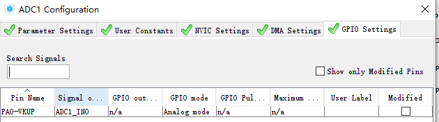
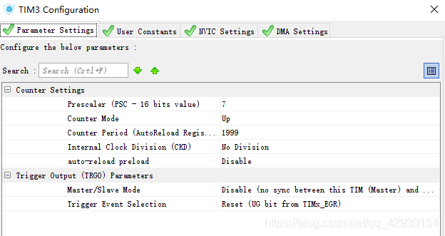
Cube配置


生成代码
完善代码
main.C里边完成
1、/* USER CODE BEGIN Includes */和/* USER CODE END Includes */中间添加
/* USER CODE BEGIN Includes */
#include "stdio.h"
/* USER CODE END Includes */
2、/* USER CODE BEGIN PV */和/* USER CODE END PV */中间添加
/* USER CODE BEGIN PV */
/* Private variables ---------------------------------------------------------*/
//==============心率============================
// these variables are volatile because they are used during the interrupt service routine!
#define true 1
#define false 0
int BPM;                   // used to hold the pulse rate
int Signal;                // holds the incoming raw data
int IBI = 600;             // holds the time between beats, must be seeded!
unsigned char Pulse = false;     // true when pulse wave is high, false when it's low
unsigned char QS = false;        // becomes true when Arduoino finds a beat.
int rate[10];                    // array to hold last ten IBI values
unsigned long sampleCounter = 0;          // used to determine pulse timing
unsigned long lastBeatTime = 0;           // used to find IBI
int P =512;                      // used to find peak in pulse wave, seeded
int T = 512;                     // used to find trough in pulse wave, seeded
int thresh = 512;                // used to find instant moment of heart beat, seeded
int amp = 100;                   // used to hold amplitude of pulse waveform, seeded
int Num;
unsigned char firstBeat = true;        // used to seed rate array so we startup with reasonable BPM
unsigned char secondBeat = false;      // used to seed rate array so we startup with reasonable BPM
//===============心率完成=========================
/* USER CODE END PV */
3、/* USER CODE BEGIN PFP */和/* USER CODE END PFP */中间添加
/* USER CODE BEGIN PFP */
/* Private function prototypes -----------------------------------------------*/
void sendDataToProcessing(char symbol, int dat );
#ifdef __GNUC__
  /* With GCC/RAISONANCE, small printf (option LD Linker->Libraries->Small printf
     set to 'Yes') calls __io_putchar() */
  #define PUTCHAR_PROTOTYPE int __io_putchar(int ch)
#else
  #define PUTCHAR_PROTOTYPE int fputc(int ch, FILE *f)
#endif /* __GNUC__ */
/* USER CODE END PFP */
4、 /* USER CODE BEGIN 2 */和 /* USER CODE END 2 */中间添加
  /* USER CODE BEGIN 2 */
	HAL_TIM_Base_Start_IT(&htim3);
  /* USER CODE END 2 */
5、
/* USER CODE BEGIN WHILE */和 /* USER CODE END WHILE */中间添加
  /* USER CODE BEGIN WHILE */
  while (1)
  {
		sendDataToProcessing('S', Signal);     // send Processing the raw Pulse Sensor data
		if (QS == true)
		{
				sendDataToProcessing('B',BPM);   // send heart rate with a 'B' prefix
				sendDataToProcessing('Q',IBI);   // send time between beats with a 'Q' prefix
				QS = false;                      // reset the Quantified Self flag for next time
		}
		HAL_Delay(20);	//delay for 20ms
  /* USER CODE END WHILE */

  /* USER CODE BEGIN 3 */

  }
  /* USER CODE END 3 */

}
6、
/* USER CODE BEGIN 4 */和/* USER CODE END 4 */中间添加/*
/* USER CODE BEGIN 4 */
PUTCHAR_PROTOTYPE
{
  /* Place your implementation of fputc here */
  /* e.g. write a character to the EVAL_COM1 and Loop until the end of transmission */
  HAL_UART_Transmit(&huart2, (uint8_t *)&ch, 1, 0xFFFF);

  return ch;
}

void HAL_TIM_PeriodElapsedCallback(TIM_HandleTypeDef *htim)
{
	unsigned int runningTotal;
	if(htim->Instance==htim3.Instance)
	{
		Signal=HAL_ADC_GetValue(&hadc1)>>2;					 // read the Pulse Senso
		sampleCounter += 2;                         // keep track of the time in mS with this variable
		Num = sampleCounter - lastBeatTime;       // monitor the time since the last beat to avoid noise
		HAL_ADC_Start(&hadc1);									//restart ADC conversion

		//  find the peak and trough of the pulse wave
  if(Signal < thresh && Num > (IBI/5)*3){       // avoid dichrotic noise by waiting 3/5 of last IBI
    if (Signal < T){                        // T is the trough
      T = Signal;                         // keep track of lowest point in pulse wave
    }
  }

  if(Signal > thresh && Signal > P){          // thresh condition helps avoid noise
    P = Signal;                             // P is the peak
  }                                        // keep track of highest point in pulse wave

  //  NOW IT'S TIME TO LOOK FOR THE HEART BEAT
  // signal surges up in value every time there is a pulse
  if (Num > 250){                                   // avoid high frequency noise
    if ( (Signal > thresh) && (Pulse == false) && (Num > (IBI/5)*3) ){
      Pulse = true;                               // set the Pulse flag when we think there is a pulse
      HAL_GPIO_WritePin(GPIOC,GPIO_PIN_13,GPIO_PIN_SET);                // turn on pin 13 LED
      IBI = sampleCounter - lastBeatTime;         // measure time between beats in mS
      lastBeatTime = sampleCounter;               // keep track of time for next pulse

      if(secondBeat){                        // if this is the second beat, if secondBeat == TRUE
        secondBeat = false;                  // clear secondBeat flag
        for(int i=0; i<=9; i++){             // seed the running total to get a realisitic BPM at startup
          rate[i] = IBI;
        }
      }

      if(firstBeat){                         // if it's the first time we found a beat, if firstBeat == TRUE
        firstBeat = false;                   // clear firstBeat flag
        secondBeat = true;                   // set the second beat flag
 //       sei();                               // enable interrupts again
        return;                              // IBI value is unreliable so discard it
      }


      // keep a running total of the last 10 IBI values
      runningTotal = 0;                  // clear the runningTotal variable

      for(int i=0; i<=8; i++){                // shift data in the rate array
        rate[i] = rate[i+1];                  // and drop the oldest IBI value
        runningTotal += rate[i];              // add up the 9 oldest IBI values
      }

      rate[9] = IBI;                          // add the latest IBI to the rate array
      runningTotal += rate[9];                // add the latest IBI to runningTotal
      runningTotal /= 10;                     // average the last 10 IBI values
      BPM = 60000/runningTotal;               // how many beats can fit into a minute? that's BPM!
      QS = true;                              // set Quantified Self flag
      // QS FLAG IS NOT CLEARED INSIDE THIS ISR
    }
  }

  if (Signal < thresh && Pulse == true){   // when the values are going down, the beat is over
     HAL_GPIO_WritePin(GPIOC,GPIO_PIN_13,GPIO_PIN_RESET);            // turn off pin 13 LED
    Pulse = false;                         // reset the Pulse flag so we can do it again
    amp = P - T;                           // get amplitude of the pulse wave
    thresh = amp/2 + T;                    // set thresh at 50% of the amplitude
    P = thresh;                            // reset these for next time
    T = thresh;
  }

  if (Num > 2500){                           // if 2.5 seconds go by without a beat
    thresh = 512;                          // set thresh default
    P = 512;                               // set P default
    T = 512;                               // set T default
    lastBeatTime = sampleCounter;          // bring the lastBeatTime up to date
    firstBeat = true;                      // set these to avoid noise
    secondBeat = false;                    // when we get the heartbeat back
  }

	}
}

void sendDataToProcessing(char symbol, int dat )
{
    putchar(symbol);                // symbol prefix tells Processing what type of data is coming
		printf("%d\r\n",dat);						// the data to send culminating in a carriage return
}
/* USER CODE END 4 */
//顺利完成 Pulse Senso传感器移植 在此记录供以后查看
最后附粘贴一个别人的心率算法
读取传感器电压值 —— STM32 ADC 功能配置
硬件配置
开发板使用的是公司的 M4 板子,传感器 3.3V 供电,信号采集选用 ADC1 的 通道 2,硬件连接如下:
| 开发板 | 传感器 |
|---|---|
| PA2 | S |
| 3V3 | + |
| GND | - |
把 PA2 用作模拟功能,配置 ADC 为 12 位分辨率,单次转换,并设置转换序列长度为 1,首次转换通道 2。为确保数据准确性,选择APB2 时钟 6 分频作为 ADC 时钟(即 84M / 6 = 14M),采样时间 480 个周期(使得采样时间更加充分),最后使能 ADC。初始化函数如下:
ADC。初始化函数如下:
/******************** ADC通道2初始化函数 ************************/void ADC_AN2_Init(void){
    /* 设置ADC功能对应的GPIO端口 */
    RCC->AHB1ENR |= 1 << 0;
    GPIOA->MODER &= ~(3 << (2 * 2));
    GPIOA->MODER |= 3 << (2 * 2);

    /* 配置ADC采样模式 */
    RCC->APB2ENR |= 1 << 8;     //使能ADC模块时钟    ADC1->CR1 &= ~(3 << 24);    //12位分辨率    ADC1->CR1 &= ~(1 << 8);     //非扫描模式    ADC1->CR2 &= ~(3 << 28);    //禁止外部触发    ADC1->CR2 &= ~(1 << 11);    //右对齐    ADC1->CR2 &= ~(1 << 1);     //单次转换    ADC->CCR &= ~(3 << 16);
    ADC->CCR |= 2 << 16;        //6分频    ADC1->SMPR2 &= ~(0x07 << 6);
    ADC1->SMPR2 |= 0x07 << 6;   //480采样周期    ADC1->SQR1 &= ~(0x0f << 20); //1次转换    ADC1->SQR3 &= ~(0x1f << 0);
    ADC1->SQR3 |= 0x02 << 0;     //转换的通道为通道2
    /* 使能ADC */
    ADC1->CR2 |= 1 << 0;          //开启ADC}
编写好初始化函数后还需要写一个进行 AD 转换的函数,这也是我们功能的核心。思路是通过将十次 AD 转换值进行冒泡排序,然后掐头去尾求平均值作为最后的转换输出值,程序如下:
/******************** ADC通道2转换函数 ************************/u16 Get_ADC_1_CH2(void){
    u8 i,j;
    u16 buff[10] = {0};
    u16 temp;

    for(i = 0; i < 10; i ++)
    {
        /* 开始转换 */
        ADC1->CR2 |= 1 << 30;

        /* 等待转换结束 */
        while( !(ADC1->SR & (1 << 1)) )
        {
            /* 等待转换接收 */
        }
        buff[i] = ADC1->DR;    //读取转换结果    }

    /* 把读取值的数据按从小到大的排列 */
    for(i = 0; i < 9; i++)
    {
        for(j = 0 ; j < 9-i; j++)
        {
            if(buff[j] > buff[j+1])
            {
                temp = buff[j];
                buff[j] = buff[j+1];
                buff[j+1] = temp;
            }
        }
    }

    /* 求平均值 */
    temp = 0;
    for(i = 1; i < 9; i++)
    {
        temp += buff[i];
    }

    return temp/8;}
串口打印,验证数据读取
是驴是马得拉出来溜溜,配好的 ADC 能不能用也要经过检验。方法是把从传感器读到的转换值在串口打印,以此测试 ADC 转换是否工作正常。为了模拟波形的效果,编写如下波形打印函数 —— 将读出来的数据缩小适当倍数后,用同一行的星号数量来表示。
void Print_Wave(void){
    int temp, i;

    temp = Get_ADC_1_CH2() / 20;   // 缩小一个倍数
    for (i = 0; i < temp; i++)
        printf("*");

    printf ("\r\n");}
在主函数的 while (1) 循环中不断调用 Print_Wave() 函数在串口打印输出,每次打印延时一段时间,代码如下:
int main(void){
    Usrat_1_Init(84,115200,0);
    Timer_6_Init();
    ADC_AN2_Init();

    while(1)
    {
        Print_Wave();
        Timer_6_Delay_ms(5);  // 延时 5 ms    }}
把开发板连接电脑,下载程序后打开串口工具接收数据,通过对传感器测量面绿光的遮挡,可在串口看到用字符打印的波形,波峰波谷清晰可见,并不懂波动,证明 ADC 读取到了传感器输出的模拟电压信号。效果如下图:
计算心率值 —— 采样数据处理算法
心率指的是一分钟内的心跳次数,得到心率最笨的方法就是计时一分钟后数有多少次脉搏。但这样的话每次测心率都要等上个一分钟才有一次结果,效率极低。另外一种方法是,测量相邻两次脉搏的时间间隔,再用一分钟除以这个间隔得出心率。这样的好处是可以实时计算脉搏,效率高。由此引出了 IBI 和 BPM 两个值的概念:
IBI: 相邻两次脉搏的时间间隔(单位:ms) BPM(beats per minute):心率,一分钟内的心跳次数
且:BPM = 60 / IBI
从网上找来的 arduino 开源算法复杂的一匹,看了一遍感觉一头雾水(反正我暂时没看懂)。由上面的分析可以得出,我们的最终目的就是要求出 IBI 的值,并通过 IBI 计算出实时心率。既然知道原理了那就自己来把算法实现吧。
核心操作 —— 识别一个脉搏信号
无论是采用计数法还是计时法,只有能识别出一个脉搏,才能数出一分钟内脉搏数或者计算两个相邻脉搏之间的时间间隔。那怎么从采集的电压波形数据判断是不是一个有效的脉搏呢?
显然,可以通过检测波峰来识别脉搏。最简单粗暴的方法是设定一个阈值,当读取到的信号值大于此阈值时便认为检测一个脉搏。似乎用一个 if 语句就轻轻松松解决。但,事情真的有那么简单么?
其实这里存在两个问题。
问题一:阈值的选取
作为判断的参考标尺,阈值该选多大?10?100?还是1000?我们不得而知,因为波形的电压范围是不确定的,振幅有大有小并且会改变,根本不能用一个写死的值去判断。就像下面这张图一样:
可以看出,两个形状相同波形的检测结果截然不同 —— 同样是波峰,在不同振幅的波形中与阈值比较的结果存在差异。实际情况正是如此:传感器输出波形的振幅是在不断随机变化的,想用一个固定的值去判定波峰是不现实的。
既然固定阈值的方法不可取,那自然想到改变阈值 —— 根据信号振幅调整阈值,以适应不同信号的波峰检测。通过对一个周期内的信号多次采样,得出信号的最高与最低电压值,由此算出阈值,再用这个阈值对采集的电压值进行判定,考虑是否为波峰。也就是说电压信号的处理分两步,首先动态计算出参考阈值,然后用用阈值对信号判定、识别一个波峰。
问题二:特征点识别
上面得出的是一段有效波形,而计算 IBI 只需要一个点。需要从一段有效信号上选取一个点,这里暂且把它称为特征点,这个特征点代表了一个有效脉搏,只要能识别到这个特征点,就能在一个脉搏到来时触发任何动作。
通过记录相邻两个特征点的时间并求差值,计算 IBI 便水到渠成。那这个特征点应该取在哪个位置呢,从官网算法说明可以看出,官方开源 arduino 代码的 v1.1 版本是选取信号上升到振幅的一半作为特征点,我们可以捕获这个特征点作为一个有效脉搏的标志,然后计算 IBI。
算法整体框架与代码实现
分析得出算法的整体框架如下:
-
缓存一个波形周期内的多次采样值,求出最大最小值,计算出振幅中间值作为信号判定阈值
-
通过把当前采样值和上一采样值与阈值作比较,寻找到「信号上升到振幅中间位置」的特征点,记录当前时间
-
寻找下一个特征点并记录时间,算出两个点的时间差值,即相邻两次脉搏的时间间隔 IBI
-
由 IBI 计算心率值 BPM
代码如下,程序中使用一个 50 长度的数组进行采样数据缓存,在主函数 while (1) 中以 20ms 的周期不断执行采样、数据处理,其中的条件语句 if (PRE_PULSE == FALSE && PULSE == TRUE) 就表示找到了特征点、识别出一次有效脉搏,串口输出心率计算结果。
int main(void){
    Usrat_1_Init(84,115200,0);
    Timer_6_Init();
    ADC_AN2_Init();

    while(1)
    {
        //Print_Wave();
        preReadData = readData;	        // 保存前一次值        readData = Get_ADC_1_CH2();		// 读取AD转换值
        if ((readData - preReadData) < filter)    // 滤除突变噪声信号干扰            data[index++] = readData;	// 填充缓存数组
        if (index >= BUFF_SIZE)
        {
            index = 0;	// 数组填满,从头再填
            // 通过缓存数组获取脉冲信号的波峰、波谷值,并计算中间值作为判定参考阈值            max = Get_Array_Max(data, BUFF_SIZE);
            min = Get_Array_Min(data, BUFF_SIZE);
            mid = (max + min)/2;
            filter = (max - min) / 2;
        }

        PRE_PULSE = PULSE;	// 保存当前脉冲状态        PULSE = (readData > mid) ? TRUE : FALSE;  // 采样值大于中间值为有效脉冲
        if (PRE_PULSE == FALSE && PULSE == TRUE)  // 寻找到「信号上升到振幅中间位置」的特征点,检测到一次有效脉搏        {
            pulseCount++;
            pulseCount %= 2;

            if(pulseCount == 1) // 两次脉搏的第一次            {
                firstTimeCount = timeCount;   // 记录第一次脉搏时间            }
            if(pulseCount == 0)  // 两次脉搏的第二次			{
                secondTimeCount = timeCount;  // 记录第二次脉搏时间                timeCount = 0;

                if ( (secondTimeCount > firstTimeCount))
                {
                    IBI = (secondTimeCount - firstTimeCount) * SAMPLE_PERIOD;	// 计算相邻两次脉搏的时间,得到 IBI                    BPM = 60000 / IBI;  // 通过 IBI 得到心率值 BPM
                    if (BPM > 200)    //限制BPM最高显示值                        BPM = 200;
                    if (BPM < 30)    //限制BPM最低显示值                        BPM=30;
                }

            }

            printf("SIG = %d IBI = %d, BMP = %d\r\n\r\n", readData, IBI, BPM);  // 串口打印调试
//          printf("B%d\r\n", BPM);  // 上位机B数据发送
//          printf("Q%d\r\n", IBI);  // 上位机Q数据发送        }

        SIG = readData - 1500;  // 脉象图数值向下偏移,调整上位机图像
        //      printf("S%d\r\n", SIG);  // 上位机S数据发送
        timeCount++;  // 时间计数累加        Timer_6_Delay_ms(SAMPLE_PERIOD);  // 延时再进行下一周期采样    }}