文章目录
此博客为学习笔记,参考:https://learnopengl-cn.github.io
camera(eye)
camera is located at the origin of coordinate, facing the negative axis
Camera/view space
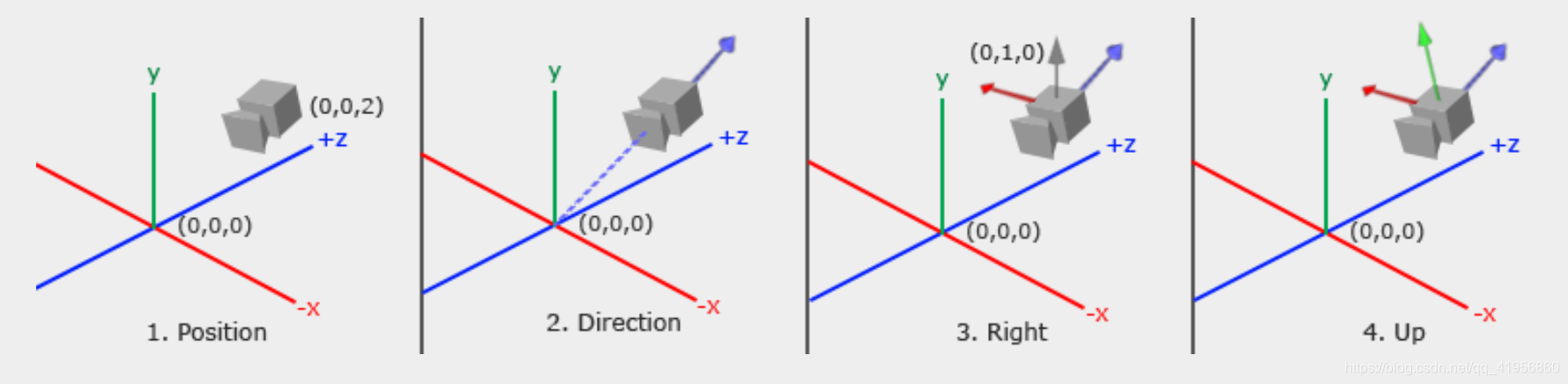
- direction: the z axis of the camera coordinate system
glm::vec3 cameraTarget = glm::vec3(0.0f, 0.0f, 0.0f);
glm::vec3 cameraDirection = glm::normalize(cameraPos - cameraTarget);
- right axis: the x axis of the camera coordinate system
// the up is usually the world up
glm::vec3 up = glm::vec3(0.0f, 1.0f, 0.0f);
glm::vec3 cameraRight = glm::normalize(glm::cross(up, cameraDirection));
- Up axis: the y axis of the camera coordinate system
glm::vec3 cameraUp = glm::cross(cameraDirection, cameraRight);
Lookat
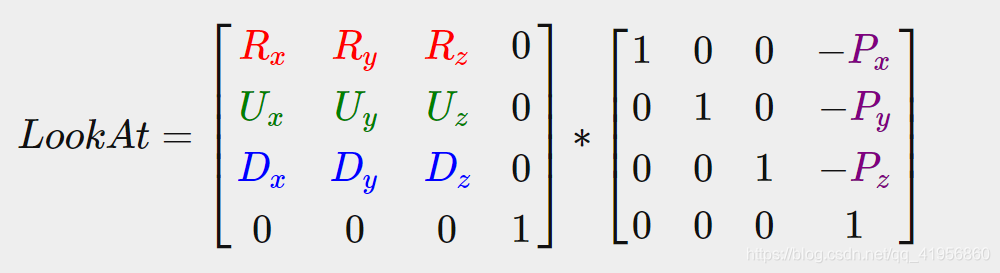
Where R is the right vector(x), U is the up vector(y), D is the direction vector(x) and P is the camera’s position vector.
glm::mat4 view;
view = glm::lookAt(glm::vec3(0.0f, 0.0f, 3.0f),   	// position
  		   glm::vec3(0.0f, 0.0f, 0.0f), 			// target
  		   glm::vec3(0.0f, 1.0f, 0.0f));			// up
Euler angles
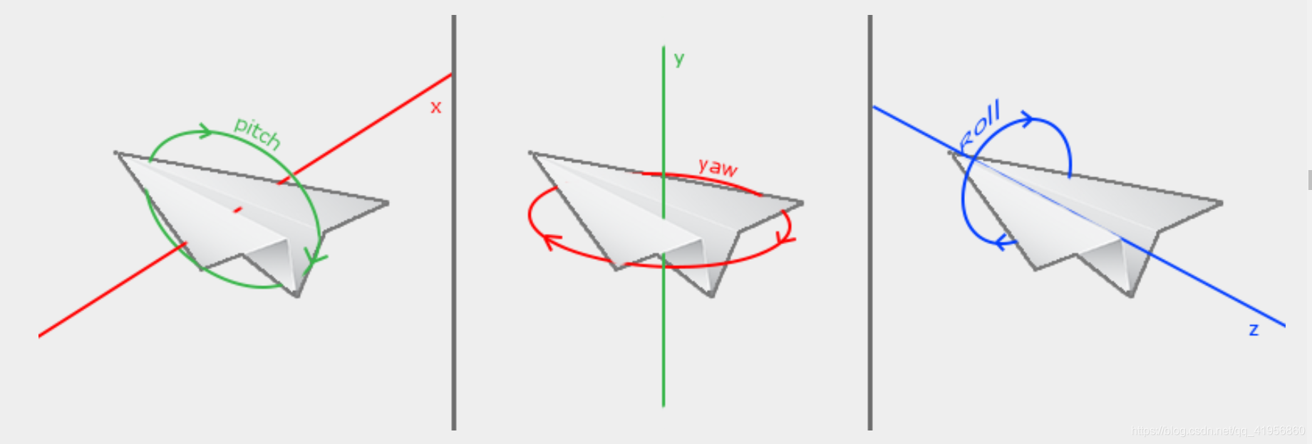
direction.x = cos(glm::radians(pitch)) * cos(glm::radians(yaw));
direction.y = sin(glm::radians(pitch));
direction.z = cos(glm::radians(pitch)) * sin(glm::radians(yaw));
mouse input
// define a callback
void mouse_callback(GLFWwindow* window, double xpos, double ypos);
// regist it
glfwSetCursorPosCallback(window, mouse_callback);
// enable it
glfwSetInputMode(window, GLFW_CURSOR, GLFW_CURSOR_DISABLED);
coordinate system
the workflow
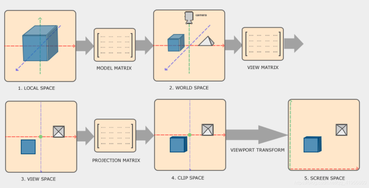
- Local coordinates are the coordinates of your object relative to its local origin; they’re the coordinates your object begins in. Every object has its own local coordinates.
- The next step is to transform the local coordinates to world-space coordinates which are coordinates in respect of a larger world. These coordinates are relative to a global origin of the world, together with many other objects also placed relative to the world’s origin.
the eye(camara) is always located at the origin of coordinate (0,0,0). I GUESS: the eye face with -z axis eternally - The view space is thus the space as seen from the camera’s point of view. This is usually accomplished with a combination of translations and rotations to translate/rotate the scene so that certain items are transformed to the front of the camera. These combined transformations are generally stored inside a view matrix that transforms world coordinates to view space.
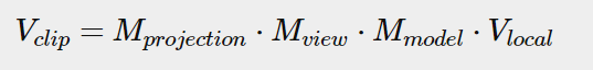
- After the coordinates are in view space we want to project them to clip coordinates. Clip coordinates are processed to the -1.0 and 1.0 range and determine which vertices will end up on the screen.
- And lastly we transform the clip coordinates to screen coordinates in a process we call viewport transform that transforms the coordinates from -1.0 and 1.0 to the coordinate range defined by glViewport. The resulting coordinates are then sent to the rasterizer to turn them into fragments.
projection
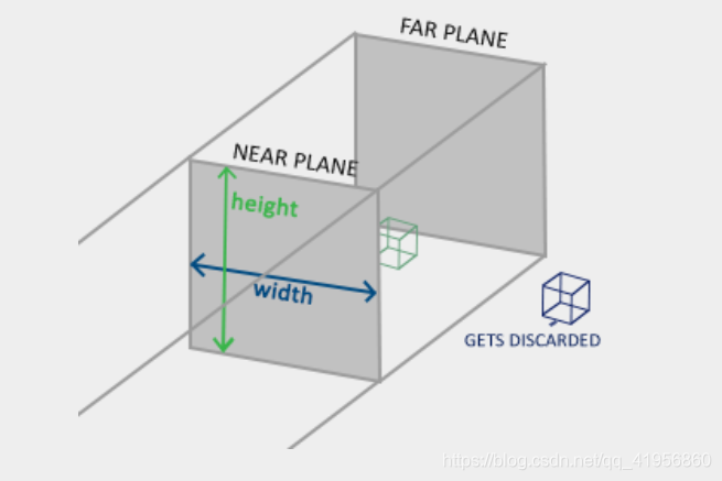
- Orthographic projection
glm::ortho(0.0f, 800.0f, 0.0f, 600.0f, 0.1f, 100.0f);
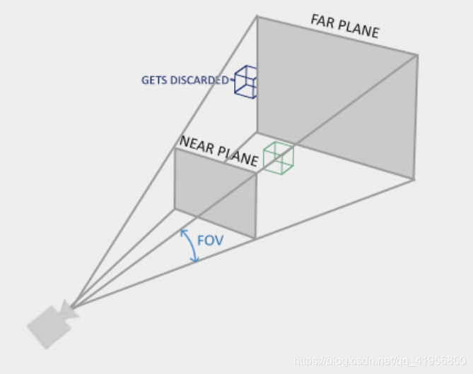
- Perspective projection
glm::mat4 proj = glm::perspective(glm::radians(45.0f), (float)width/(float)height, 0.1f, 100.0f);
due to perspective the lines seem to coincide the farther they’re away. This is exactly the effect perspective projection tries to mimic and it does so using a perspective projection matrix. The projection matrix maps a given frustum range to clip space, but also manipulates the w value of each vertex coordinate in such a way that the further away a vertex coordinate is from the viewer, the higher this w component becomes. Once the coordinates are transformed to clip space they are in the range -w to w (anything outside this range is clipped). OpenGL requires that the visible coordinates fall between the range -1.0 and 1.0 as the final vertex shader output, thus once the coordinates are in clip space, perspective division is applied to the clip space coordinates:
z-buffer, depth test
OpenGL stores all its depth information in a z-buffer, also known as a depth buffer. GLFW automatically creates such a buffer for you (just like it has a color-buffer that stores the colors of the output image). The depth is stored within each fragment (as the fragment’s z value) and whenever the fragment wants to output its color, OpenGL compares its depth values with the z-buffer and if the current fragment is behind the other fragment it is discarded, otherwise overwritten. This process is called depth testing and is done automatically by OpenGL.
glEnable(GL_DEPTH_TEST);
glClear(GL_COLOR_BUFFER_BIT | GL_DEPTH_BUFFER_BIT);
demo code
// shader
#version 330 core
layout (location=0) in vec3 aPos;
uniform mat4 model;
uniform mat4 view;
uniform mat4 project;
void main(){
	gl_Position = project * view * model * vec4(aPos, 1.0);
}

// pass the data
glm::mat4 model = glm::mat4(1.0f); // make sure to initialize matrix to identity matrix first
glm::mat4 view = glm::mat4(1.0f);
glm::mat4 projection = glm::mat4(1.0f);
model = glm::rotate(model, (float)glfwGetTime(), glm::vec3(0.5f, 1.0f, 0.0f));
view = glm::translate(view, glm::vec3(0.0f, 0.0f, -3.0f));
projection = glm::perspective(glm::radians(45.0f), (float)SCR_WIDTH / (float)SCR_HEIGHT, 0.1f, 100.0f);
ourShader.setMat4("model", model);
ourShader.setMat4("view", view);
// note: currently we set the projection matrix each frame, but since the projection matrix rarely changes it's often best practice to set it outside the main loop only once.
ourShader.setMat4("project", projection);
Transformation
a course about matrix transformation : https://www.khanacademy.org/math/linear-algebra/matrix-transformations
mathmatic basics
vector- vector multipilcation
- Dot product
- Cross product
Matrix-vector multiplication (scaling, Translatioin, Rotation)
- scale
- translate
Homogeneous coordinates
The w component of a vector is also known as a homogeneous coordinate. To get the 3D vector from a homogeneous vector we divide the x, y and z coordinate by its w coordinate. We usually do not notice this since the w component is 1.0 most of the time. Using homogeneous coordinates has several advantages: it allows us to do translations on 3D vectors (without a w component we can’t translate vectors) .
Also, whenever the homogeneous coordinate is equal to 0 the vector is specifically known as a direction vector since a vector with a w coordinate of 0 cannot be translated.
- rotate
A rotation matrix is defined for each unit axis in 3D space where the angle is represented as the theta symbol θ.
for example, Rotation around the X-axis:
we can make an object rotate around arbitrary unit axis by combining rotation matrix. But we use a matrix to make it.
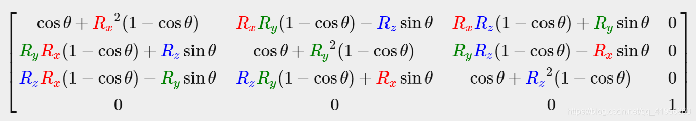
the rotate axis is
,Attention:
must be a unit vector. rotate angle is
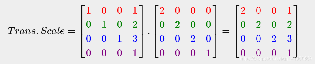
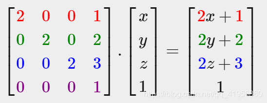
combine matrix
e.g. Scale and then translate
GLM
the website for download: https://glm.g-truc.net/0.9.8/index.html
eg:
// includes
#include <glm/glm.hpp>
#include <glm/gtc/matrix_transform.hpp>
#include <glm/gtc/type_ptr.hpp>

// vertex shader
#version 330 core
layout (location = 0) in vec3 aPos;
uniform mat4 transform;
void main()
{
    gl_Position = transform * vec4(aPos, 1.0f);
}

// get transformation matrix
glm::mat4 trans = glm::mat4(1.0f);
trans = glm::translate(trans, glm::vec3(1.0f, 1.0f, 0.0f));
trans = glm::rotate(trans, glm::radians(90.0f), glm::vec3(0.0, 0.0, 1.0));
trans = glm::scale(trans, glm::vec3(0.5, 0.5, 0.5));

// set the data
unsigned int transformLoc = glGetUniformLocation(ourShader.ID, "transform");
glUniformMatrix4fv(transformLoc, 1, GL_FALSE, glm::value_ptr(trans));
// glUniformMatrix4fv(transformLoc, 1, GL_FALSE, &trans[0][0]);
