reference:
Volumetric Light Effects in Killzone: Shadow Fall [1]
Interactive Rendering Method for Displaying Shafts of Light [2]
游戏开发相关实时渲染技术之体积光 [3]
本文包含的内容:
| 1.体积光介绍 2.使用Ray-match实现最基本的体积光 3. 加入大气散射效果 4.体积光遮挡关系计算,实现缝隙穿过体积光效果 5.体积光性能优化,半分辨率 + 随机扰动采样位置 |
场景中往往有很多比较"虚"的东西,比如烟、雾、光、云等,关于制作这类效果,我之前所知道的方法包括比较trick的,如用billborad和uv动画来做障眼法;又或是比较复杂的,用粒子来模拟。最近了解到有一种比较常见的方法,也就是用体素(体绘制)的方法来绘制物体。这是一个比较有意思的思路,因为在三维造型中,网格表达是非常常见的,但是在这种表达之下,物体往往是“空心"的。而更加符合人直觉的表达空间中三维物体的方法,应该是记录物体在空间哪些位置存在,存在则为1,不存在则记录为0,这就引出了体绘制的概念。
本次我们更侧重于用体素的思想来渲染不存在实体的”体积光“。也就是说,我们可以不为体积光绘制mesh,而是直接在着色器中,在物体所在的位置,直接进行绘制。体素只是一种绘制的思想,它的实现有很多方法。
体积光
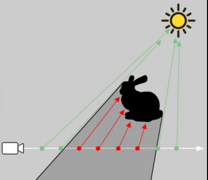
首先,我们要确认一下什么是体积光。体积光通俗来说是我们能看见的”光路“,并不是所有灯光都会形成体积光效果,它是光照到大气中粒子散射后得到的效果(丁达尔效应)。我们有时候还会看到一束束光散开的效果,这是光在传播过程中遇到了障碍物(比如穿过云层、树木的光束)导致的。
根据物理原理,我们知道体积光是粒子散射的结果,如果我们用体素的思想来考虑体积光,我们所看到的某一点处的体积光颜色是眼睛到当前点的射线上,光路中所有粒子散射光的叠加。基于这一思路,我们引入Ray-match的方式来模拟体积光。
备注:以下代码实现均基于延迟渲染。
最基本的Ray-Match
Ray-Match也就是从眼睛向场景发出许多条射线。对于每条射线而言,我们截取落在体积光中的线段,并每次推进一定步长在线段中进行位置采样,并做散射光强的计算,最终把所有结果加在一起,得到当前位置的光强。
在延迟渲染的框架中,我们可以在g-buffer的后处理过程中完成这一过程。在不考虑任何优化的情况下,我们可以逐像素做这件事(一般情况下,我们会做降采样)。也就是对屏幕上的每个像素,从眼睛处经过该像素的位置发出射线,然后按一定步长采样,把所有结果加起来,计算最终的像素颜色。
在具体实现中,对于每个像素而言,我们要考虑的问题是,我们应该从射线的何处开始采样,何处停止采样,以及采样的步长应该为多少。
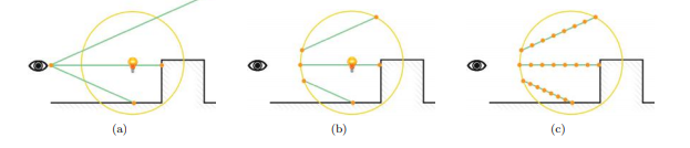
确定采样的起点和终点,我们可以给出三种做法:
(1) 无需求交,直接从近裁剪面裁剪到当前深度采样。适用于全屏阳光,也可用于区域光,但对后者而言,采样精度较低,因为采样的大部分位置并没有落在体积光内,会出现重影现象,要达到同样的效果需要更多的采样点。
(2) 通过求交,求出光所在的范围,在该范围内采样。适用于区域光。问题在于对复杂几何体求交对性能损耗很大,像球体这样的光源则会简化不少。
(3) 渲染光所在范围的几何体正面和背面的深度,然后利用这个深度来确定采样的范围。缺点在于会消耗2个通道,如果在延迟渲染框架下,我们不一定有位置留给这两个通道,但是计算很简单,适用于复杂几何体。
还有一种思路是,直接绘制几何体,然后在几何体的着色器中算体积光的像素颜色。不过这也需要求得几何体每个位置的深度。
对于全屏的体积光,我们不一定要最远采样到远裁剪面,也可以自己设定一个采样终止点,当体积光距离视点达到一定距离时,可以将它视为不重要信息,所以可以无需绘制,来提升体积光的渲染性能。

以下是利用无需求交的方式计算的体积光:
点光源的示例代码(G-Buffer后处理部分),以下代码中ray-match推进求世界坐标的代码可简化,不需要每次求逆,利用起始坐标和视线方向即可。 (pos = viewpos + viewdir * step)
vertex shader
#version 450 core
uniform float fov;
uniform float zFar;
uniform float aspect;
attribute vec4 a_position;
attribute vec2 a_texcoord;

varying vec2 v_texcoord;
varying vec2 farPlanePos;

void main()
{
    gl_Position = a_position;
    v_texcoord = a_texcoord;

    float t = tan(fov/2);
    farPlanePos.x = (v_texcoord.x * 2 - 1) * zFar * t*aspect;
    farPlanePos.y = (v_texcoord.y * 2 - 1) * zFar * t;
}
fragment shader
#version 450 core

in vec2 v_texcoord;

uniform vec3 cameraPos;
uniform vec3 lightPosition;
uniform sampler2D NormalAndDepth;
uniform sampler2D ColorTex;
uniform mat4 Inverse_ViewMatrix;

uniform float zFar;
uniform float zNear;

varying vec2 farPlanePos;

vec3 yellow_light = vec3(1,198.0/255.0,107.0/255.0);

// use linear z depth
vec3 ComputeWorldPos(float depth)
{
    vec4 pos = vec4(vec3(farPlanePos.x, farPlanePos.y,-zFar) * depth , 1);
    vec4 ret = Inverse_ViewMatrix * pos;
    return ret.xyz / ret.w;
}

void main(void)
{
    vec4 result = texture2D(NormalAndDepth, v_texcoord);

    vec3 normal = result.xyz * 2 - 1;
    float depth = result.w;
    vec3 worldPos = ComputeWorldPos(depth);

    vec3 result;

    // 体积光
    {
        float I = 0.0;
        float d = depth * zFar;
        int virtual_plane_num = 100;
        int begin = int(virtual_plane_num * zNear / (d - zNear));
        int end = int(virtual_plane_num * (zFar - d) / (d - zNear));
        for(int j = begin;j <= virtual_plane_num + begin;j++)
        {
            float z = 1.0 * j / (begin + virtual_plane_num + end);
            // the judge below can be ignored
            if(z < depth)
            {
                vec3 pos = ComputeWorldPos(z);

                vec3 lightDis = pos - lightPosition;
                float lightDis2 = lightDis.x * lightDis.x + lightDis.y * lightDis.y + lightDis.z * lightDis.z;

                float attenuation = 1.0 / (0.05 * lightDis2);
                I += clamp(attenuation  / virtual_plane_num ,0,1);
            }


        }
        I = clamp(I,0,1);
        result += I * yellow_light;

    }

    // 加一层平行光源
    {
        vec3 ViewDir = normalize( cameraPos - worldPos );
        vec3 lightDir = normalize(vec3(0.5,1,0.2) );
        vec3 halfDir = normalize(lightDir + ViewDir);
        float diffuse = 0.3 * clamp(dot(normal, lightDir), 0, 1) ;
        vec3 reflectDir = normalize(reflect(-lightDir,normal));
        float specular =  0.3 * pow(clamp(dot(reflectDir,halfDir),0,1),50.0);
        vec3 color = (diffuse + specular) *vec3(1,1,1);
        result += color;
    }
    float ambient = 0.3;

    vec3 color = vec3(texture2D(ColorTex,v_texcoord));
    gl_FragColor = vec4(result + ambient * vec3(1,1,1),1);

}
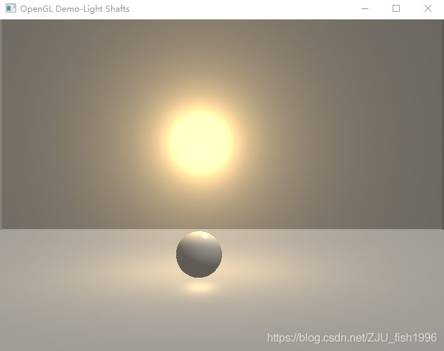
Mie散射

为了模拟更真实的物理效果,我们可以考虑对像太阳光这样的光源加入大气散射的效果,可以模拟大气环境表现。
(网上有两种计算方式,包括(1-g)^2和1-g^2,我也不清楚哪个是对的,上图是用第二个来计算的)
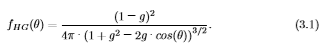
我们选用hg公式作为Mie散射效应的一个近似,然后将计算得到的光照结果乘以hg系数,作为大气散射的衰减,最终的效果如上图。具体计算如下:
vec3 lightDis = pos - lightPosition;
vec3 viewDis = pos - cameraPos;

vec3 lightDir = normalize(lightDis);
vec3 viewDir = normalize(viewDis);
float cosTheta = dot(lightDir,-viewDir);

float hg = 1.0/(4*3.14)* (1 - g*g)/ pow(1 + g*g -2*g * cosTheta , 1.5);
遮挡关系
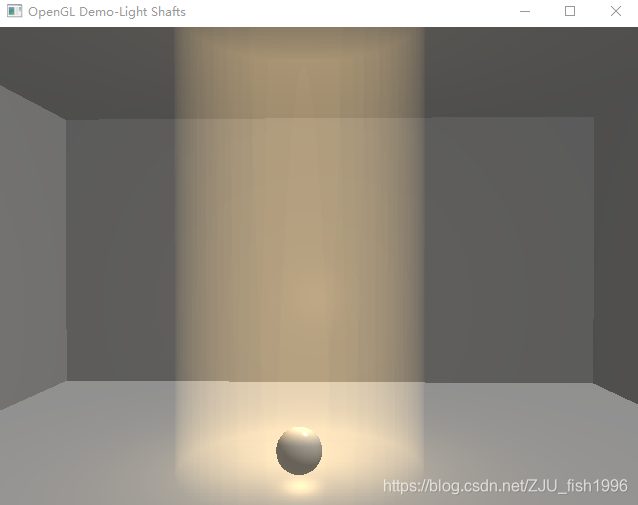
我们常常看到这样的场景,阳光穿过云层或者树林,一缕缕撒在地面上;或是一束光透过窗户,照亮黑暗的小屋之类的效果。这些都是因为光遇到了障碍物,因而不再前行,只有不被遮挡的光才最终达到更远的地方,才形成了特定的光效。
参考文章[3]给出的一个比较直观的方法是:连接采样点与光源,判断线段是否与场景物体相交。我们知道线段与复杂物体的求交是很复杂的,它意味着我们要遍历所有的三角形。游戏中一般是通过AABB包围盒来简化判断点选,但点选对判断精度要求较低,此处对遮挡关系计算要求较高,否则投射的光线位置会不对。
所以此处采用的是参考文章[2]给出的基于shadow map的方法,它的基本思路是,对于每一个采样点,通过阴影图采样,来判断它是否落在阴影中,这个算法本身比较简单,主要麻烦的在于shadow map的实现。对于聚光灯而言,实现的demo效果如下:


以上demo的shadow map是基于透视投影的,也就是它只适用于像这样的聚光灯表达。
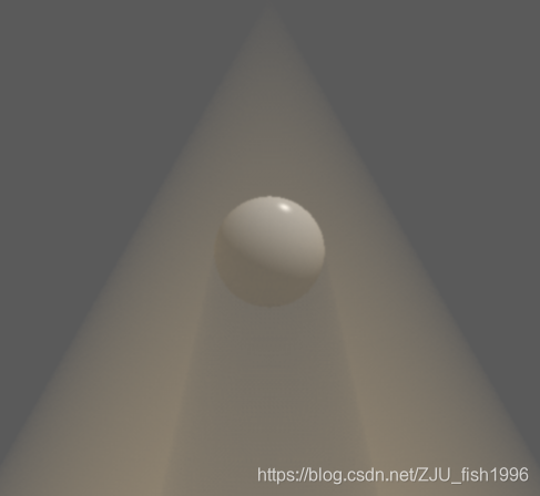
在参考文章[1]中,Killzone给出了这么一个效果图:

要实现以上效果,我们需要使用cube shadowmap,也就是要对点光源周围一圈的遮挡关系在光源位置做采样,并记录到cube texture中,我们才能获得所有的遮挡信息。
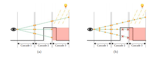
此外,如果想要实现像太阳光这样的平行光(非区域光),我们需要使用基于正交投影,加上cascade shadowmap,即多层级阴影映射,以保证尽可能采样到场景中所有物体的遮挡关系(如下图)。因为一个shadow map能够采样到的范围是有一定限度的。
以下给出聚光灯的遮挡计算代码:
写入阴影部分。这里就直接把深度放在一个通道里了,使用透视投影,线性深度。
vertex shader:
#version 450 core

uniform mat4 ProjectMatrix;
uniform mat4 LightMatrix;
uniform mat4 ModelMatrix;

attribute vec4 a_position;

varying vec2 v_depth;

void main()
{
    gl_Position = ModelMatrix * a_position;
    gl_Position = LightMatrix * gl_Position;
    v_depth = gl_Position.zw;
    gl_Position = ProjectMatrix * gl_Position;
}
fragment shader:
#version 450 core

varying vec2 v_depth;
uniform float zFar;

void main()
{
    float fColor =  -(v_depth.x/v_depth.y )/zFar;
    gl_FragColor = vec4(fColor,fColor,fColor,1);
}
后处理部分,仅做了简单的阴影采样,未做抗锯齿(因为多层采样下不做影响并不大)
vertex shader:
#version 450 core
uniform float fov;
uniform float zFar;
uniform float aspect;
attribute vec4 a_position;
attribute vec2 a_texcoord;

varying vec2 v_texcoord;
varying vec2 farPlanePos;

void main()
{
    gl_Position = a_position;
    v_texcoord = a_texcoord;

    float t = tan(fov/2);
    farPlanePos.x = (v_texcoord.x * 2 - 1) * zFar * t*aspect;
    farPlanePos.y = (v_texcoord.y * 2 - 1) * zFar * t;
}
fragment shader:
#version 450 core

in vec2 v_texcoord;

uniform vec3 cameraPos;
uniform sampler2D NormalAndDepth;
uniform sampler2D ColorTex;
uniform sampler2D ShadowMap;
uniform mat4 Inverse_ViewMatrix;
uniform mat4 LightMatrix;
uniform mat4 ProjectMatrix;
uniform float g;
uniform float zFar;
uniform float zNear;
uniform vec3 lightPosition;

varying vec2 farPlanePos;

vec3 yellow_light = vec3(1,198.0/255.0,107.0/255.0);

vec3 ComputeWorldPos(float depth)
{
    vec4 pos = vec4(vec3(farPlanePos.x, farPlanePos.y,-zFar) * depth , 1);
    vec4 ret = Inverse_ViewMatrix * pos;
    return ret.xyz / ret.w;
}

bool IsInShadow(vec4 worldPos)
{
    float fShadow = 0.0;
    vec4 lightPos = (LightMatrix * (worldPos));
    float fDistance = -lightPos.z / zFar;
    lightPos = ProjectMatrix * lightPos;

    vec2 uv = lightPos.xy / lightPos.w * 0.5 + vec2(0.5, 0.5);

    uv.x = clamp(uv.x, 0, 1);
    uv.y = clamp(uv.y, 0, 1);

    float offset = 0.5/zFar;

    float distanceMap = texture2D(ShadowMap, uv).r;
    return fDistance - offset > distanceMap;
}

void main(void)
{
    vec4 result = texture2D(NormalAndDepth, v_texcoord);

    vec3 normal = result.xyz * 2 - 1;
    float depth = result.w;
    vec3 worldPos = ComputeWorldPos(depth);

    vec3 total_light;

    // 体积光
    {
        float I = 0.0;
        float d = depth * zFar;
        int virtual_plane_num = 100;
        int begin = int(virtual_plane_num * zNear / (d - zNear));
        int end = int(virtual_plane_num * (zFar - d) / (d - zNear));
        for(int j = begin;j <= virtual_plane_num + begin;j++)
        {
            float z = 1.0 * j / (begin + virtual_plane_num + end);

            vec3 pos = ComputeWorldPos(z);
            if(z < depth && !IsInShadow(vec4(pos,1)))
            {
                vec3 lightDis = pos - lightPosition;
                vec3 viewDis = pos - cameraPos;

                float lightDis2 = lightDis.x * lightDis.x + lightDis.y * lightDis.y  + lightDis.z * lightDis.z;

                vec3 lightDir = normalize(lightDis);
                vec3 viewDir = normalize(viewDis);

                float cosTheta = dot(lightDir,normalize(-lightPosition));
                float hg = 1.0/(4*3.14)* (1 - g*g)/ pow(1 + g*g -2*g * dot(lightDir,-viewDir), 1.5);
                if(cosTheta > 0.9)
                {
                    I += clamp(10 * hg / virtual_plane_num, 0, 1);
                }
            }

        }
        I = clamp(I,0,1);
        total_light += I * yellow_light;

    }

    // 平行光源
    {
        vec3 ViewDir = normalize( cameraPos - worldPos );
        vec3 lightDir = normalize(vec3(0.5,1,0.2) );
        vec3 halfDir = normalize(lightDir + ViewDir);
        float diffuse = 0.3 * clamp(dot(normal, lightDir), 0, 1) ;
        vec3 reflectDir = normalize(reflect(-lightDir,normal));
        float specular =  0.3 * pow(clamp(dot(reflectDir,halfDir),0,1),50.0);
        vec3 color = (diffuse + specular) *vec3(1,1,1);
        total_light += color;
    }

    float ambient = 0.3;
    vec3 color = vec3(texture2D(ColorTex,v_texcoord));
    gl_FragColor = vec4(total_light + ambient * vec3(1,1,1),1);
}
优化
体积光的计算消耗比较大,按照原先的计算,在pc等平台上会有卡顿,而几乎无法用于移动平台。所以,我们需要在此基础上考虑一些优化的方式。
我们的Ray-match主要包括了两部分内容,一部分是发出多条视线,另一部分是在视线上进行采样。所以我们的优化也可以从两方面着手,一方面是减少发出的视线,一方面是减少某一视线上的采样数,同时保证效果不打太大的折扣。
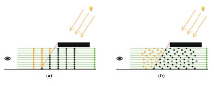
网格点计算+硬件线性插值
参考文章[2]中给出的思路是,仅对屏幕一部分点发出射线计算采样结果,剩余结果通过硬件自带的Gouraud线性插值得到。
根据论文描述的方法,我猜测它的做法是,在延迟渲染绘制屏幕四边形时,我们一般绘制只有四个顶点、两个三角形组成的全屏四边形即可。而在该方法中,我们根据采样网格精度绘制成有更多三角形的屏幕四边形,如40x40的网格点。
然后,我们在顶点着色器中,计算网格点处的像素颜色,然后通过硬件插值进而得到屏幕上每个点的像素颜色。它有一个缺陷是,在明暗交界处可能因为采样不够而导致效果错误。原论文中已经给出了不同网格点大小的效果对比。
半分辨率采样
为了减少采样数,我们可以将体积光单独渲染到一张纹理,该纹理的宽高均为屏幕大小的一半。为此,我们要做的是:
(1) 生成屏幕一半大小的纹理,作为体积光写入纹理:
// ...
 GenerateFrameBuffer(lightBufferTex, lightBuffer,screenX/2,screenY/2);
//...


void RenderCommon::GenerateFrameBuffer(GLuint& texId, GLuint& bufferId,int x, int y)
{
    glBindFramebuffer(GL_FRAMEBUFFER, bufferId);

    glGenTextures(1, &texId);
    glBindTexture(GL_TEXTURE_2D, texId);
    glTexImage2D(GL_TEXTURE_2D, 0, GL_RGB16F_ARB, x, y, 0, GL_RGB, GL_FLOAT, nullptr);
    glTexParameteri(GL_TEXTURE_2D, GL_TEXTURE_MIN_FILTER, GL_LINEAR);
    glTexParameteri(GL_TEXTURE_2D, GL_TEXTURE_MAG_FILTER, GL_LINEAR);
    glTexParameteri(GL_TEXTURE_2D,GL_TEXTURE_WRAP_S,GL_CLAMP);
    glTexParameteri(GL_TEXTURE_2D,GL_TEXTURE_WRAP_T,GL_CLAMP);
    glBindTexture(GL_TEXTURE_2D, 0);

    glFramebufferTexture2D(GL_FRAMEBUFFER, GL_COLOR_ATTACHMENT0, GL_TEXTURE_2D, texId, 0);

}
(2) 渲染时,绘制1/4屏幕的四边形,而不是绘制全屏四边形。
作为对比,这是全屏四边形的顶点数据:
    const int vertexNum = 4;
    VertexData Vertices[vertexNum];
    Vertices[0].position = QVector3D(-1.0f, -1.0f, 0.0f); Vertices[0].texcoord = QVector2D(0,0);
    Vertices[1].position = QVector3D(1.0f,  -1.0f, 0.0f); Vertices[1].texcoord = QVector2D(1,0);
    Vertices[2].position = QVector3D(1.0f,  1.0f,  0.0f); Vertices[2].texcoord = QVector2D(1,1);
    Vertices[3].position = QVector3D(-1.0f, 1.0f,  0.0f); Vertices[3].texcoord = QVector2D(0,1);
这是半屏四边形的顶点数据:
    const int vertexNum = 4;
    VertexData Vertices[vertexNum];
    Vertices[0].position = QVector3D(-1.0f, -1.0f, 0.0f); Vertices[0].texcoord = QVector2D(0,0);
    Vertices[1].position = QVector3D(0.0f,  -1.0f, 0.0f); Vertices[1].texcoord = QVector2D(1,0);
    Vertices[2].position = QVector3D(0.0f,  0.0f,  0.0f); Vertices[2].texcoord = QVector2D(1,1);
    Vertices[3].position = QVector3D(-1.0f, 0.0f,  0.0f); Vertices[3].texcoord = QVector2D(0,1);
其余计算和之前保持一致。
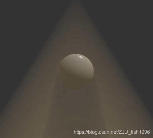
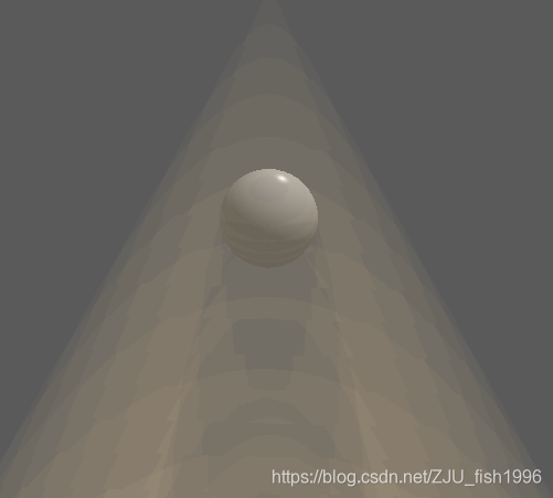
可以看到,使用半分辨率后,(球)边缘有那么模糊:
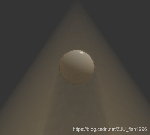
为了保持边缘锐利,我们可以做一次双边插值。
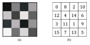
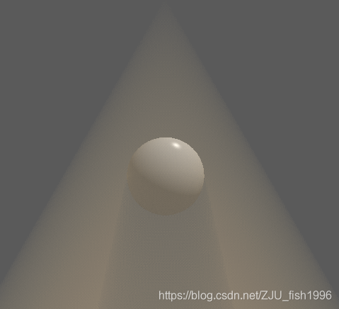
使用dither纹理
此处我们使用参考文章[1]给出的思路,Dithered Ray Marching,使用伪随机在屏幕空间做采样位置的偏移。最后在对图像做一次模糊,如下图所示:
使用的伪随机偏移纹理为:
经过该操作,最终图像的锯齿感会明显下降,因此我们可以在此基础上降低分辨率或者减少某条光线上的采样点,而不降低渲染图像的质量。
然后,再做一次模糊。需要用两个pass来完成双边高斯模糊效果。为什么使用两次一维而不是一次二维卷积?我猜测应该是一维的运算速度更快,可以让人忽略两次pass的消耗。
此外,模糊仅对体积光生效(单独写入一张buffer),不影响场景物体。
以下是我的测试结果:
以下是实现部分:
因为准备一个纹理比较麻烦,所以此处我直接使用了矩阵,构造方式如下:
mat4 dither = mat4(
   0,       0.5,    0.125,  0.625,
   0.75,    0.25,   0.875,  0.375,
   0.1875,  0.6875, 0.0625, 0.5625,
   0.9375,  0.4375, 0.8125, 0.3125
);
以下是体积光计算的部分:
float I = 0.0;
float d = depth * zFar;
int virtual_plane_num = 40;
int sampleCoordX = int(mod((ScreenX * v_texcoord.x),4));
int sampleCoordY = int(mod((ScreenY * v_texcoord.y),4));

int begin = int(virtual_plane_num * zNear / (d - zNear));
int end = int(virtual_plane_num * (zFar - d) / (d - zNear));
int total = begin + virtual_plane_num + end;
float offset = 1.0 / total * dither[sampleCoordX][sampleCoordY];
for(int j = begin;j <= virtual_plane_num + begin;j++)
{
    float z = 1.0 * j / total + offset;

    vec3 pos = ComputeWorldPos(z);
    if(z < depth && !IsInShadow(vec4(pos,1)))
    {
        vec3 lightDis = pos - lightPosition;
        vec3 viewDis = pos - cameraPos;

        vec3 lightDir = normalize(lightDis);
        vec3 viewDir = normalize(viewDis);

        float cosTheta = dot(lightDir,normalize(-lightPosition));
        float hg = 1.0/(4*3.14)* (1 - g*g)/ pow(1 + g*g -2*g * dot(lightDir,-viewDir), 1.5);
        if(cosTheta > 0.9)
        {
            I += clamp(10 * hg / virtual_plane_num, 0, 1);
        }
    }
    I = clamp(I,0,1);
    total_light += I * yellow_light;
}
模糊部分,为了简化此处只用了一次pass。
#version 450 core

uniform sampler2D Light;
uniform int ScreenX;
uniform int ScreenY;
varying vec2 v_texcoord;

void main(void)
{
    const int size = 7;


    float gauss[] = float[]
    (
        0.00000067, 0.00002292, 0.00019117, 0.00038771, 0.00019117, 0.00002292, 0.00000067,
        0.00002292, 0.00078633, 0.00655965, 0.01330373, 0.00655965, 0.00078633, 0.00002292,
        0.00019117, 0.00655965, 0.05472157, 0.11098164, 0.05472157, 0.00655965, 0.00019117,
        0.00038771, 0.01330373, 0.11098164, 0.22508352, 0.11098164, 0.01330373, 0.00038771,
        0.00019117, 0.00655965, 0.05472157, 0.11098164, 0.05472157, 0.00655965, 0.00019117,
        0.00002292, 0.00078633, 0.00655965, 0.01330373, 0.00655965, 0.00078633, 0.00002292,
        0.00000067, 0.00002292, 0.00019117, 0.00038771, 0.00019117, 0.00002292, 0.00000067
    );


   vec3 finalColor = vec3(0,0,0);

   int idx = 0;
   for(int i = -3;i <= 3;i++)
   {
       for(int j = -3; j <= 3;j++)
       {
           vec2 uv = v_texcoord + vec2(1.0 * i /ScreenX, 1.0 * j /ScreenY);
           vec3 color = texture2D(Light, uv).xyz;
           float weight = gauss[idx];
           finalColor = finalColor + weight * color;
           idx++;
       }
   }

   gl_FragColor = vec4(finalColor, 1);
}