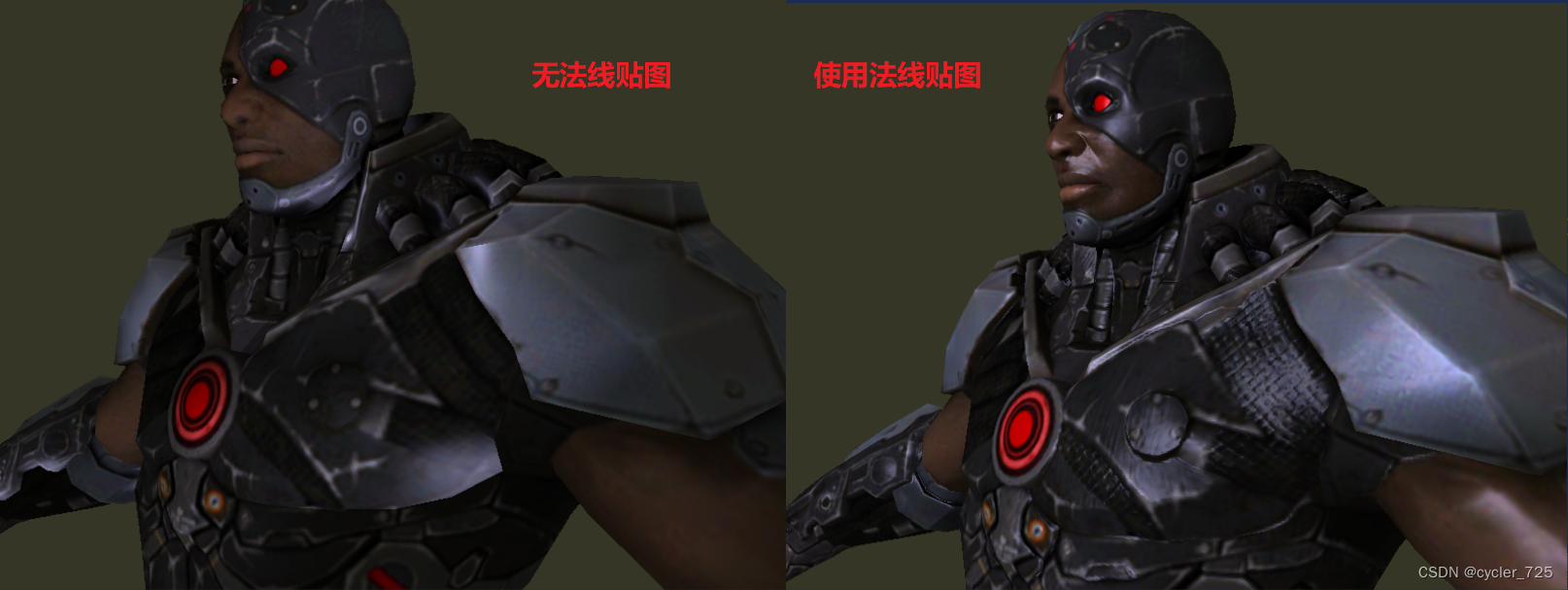
文在Blinn-phong光照模型基础上添加法线贴图。
看案例的时候总感觉很简单,但是自己写了之后发现还是有很多细节要注意的。
1.法线贴图
1.1 基本原理
借助一张纹理贴图颜色值(RGB)存储物体的表面法线方向,比如下面这张图,大部分是蓝色RGB:(0,0,1),对应了法线方向(0,0,1).
但是法线范围应该是【-1,1】,表示正反两个方向,所以要进行转化。
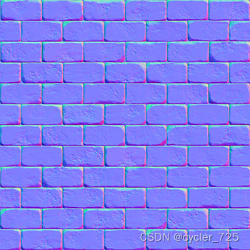
适合少顶点的情况下增加真实感,在多顶点情况下对比不是很大。
1.2 基本实现
仍然是基于原来的漫反射贴图计算光照,但是在漫反射和高光反射的计算上会更加细致,因为两者都与法线相关。
漫反射:

高光反射:
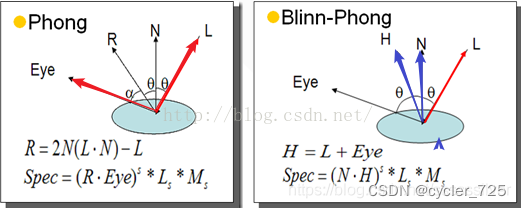
Blinn-phong光照计算公式:

2. TBN矩阵
2.1 基本原理
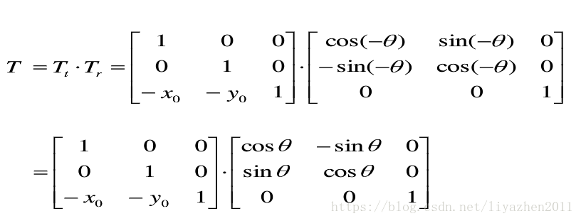
一开始想一个向量如何转换到另一个坐标,就是进行平移然后旋转(不考虑缩放)。
平移的话直到两个原点就行了,但是旋转还需要知道沿着三个向量的旋转角度。所以并不好求。


引入TBN矩阵
给定三个相互垂直的基向量确定一个坐标系,坐标其实就是该点在三个基向量上的投影大小,也就是点乘。
也就是说如果想将一个坐标P从A坐标系变换到B坐标系,知道三个相互垂直的基向量(A坐标系),将这三个基向量用B坐标系表示即可,然后对点P分别对三个向量求点乘即可(得到投影大小)。
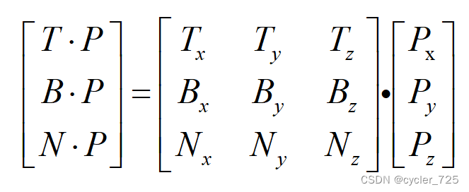
T、B、N是行向量表示的
注:正交矩阵(每个轴既是单位向量同时相互垂直)的置换矩阵与它的逆矩阵相等。这个属性很重要因为逆矩阵的求得比求置换开销大;结果却是一样的。
2.2 求TBN矩阵
因为已经直到原来的法线,求TBN矩阵其实只需要求其中一个切线即可,因为副切线可以用切线和法线的叉乘求到。
对于简单的平面
我们可以手工计算切线。
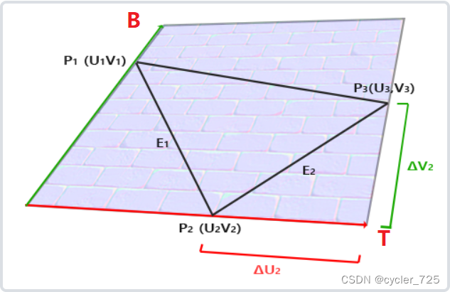
这里的计算都是在切线空间下计算的(后续再转化到世界空间里),默认T和B是沿着xy方向。
两条线缺点一个平面,将两个方向向E1、E2用基函数进行表示,可以得到下面的式子:
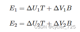
矩阵表示如下:

两边左乘UV矩阵的逆矩阵,结果最终可以表示为:

对于复杂模型
当我们需要对复杂多面体进行计算时,就需要为每个加载的顶点计算出柔和的切线和副切线向量,这明显是很庞大的工作量。因为每个顶点对应的切线空间可能都是不同的。
好在我们不需要手工计算每个顶点对应的切线和副切线,assimp库(Open Asset Import Library)在加载模型时候帮我们计算好了每个顶点的信息。我们只需要读取,然后放入缓存中传递到着色器程序。
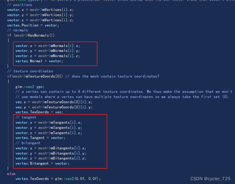
2.3 格拉姆-施密特正交化(Gram-Schmidt process)
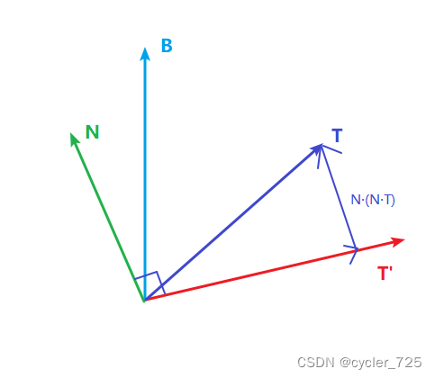
原因:求得TBN三个基函数后,其实这三个基向量不一定是两两垂直的。这意味着TBN矩阵不再是正交矩阵了,法线贴图可能会稍稍偏移。
首先副切线B是用切线和法线的叉乘求到,所以B和T、N是相互垂直的。
所以对T或者N,需要进行正交化,这里对T进行修正,简单理解如下:T' + N(NT)=T,求出T'然后单位化即可。

3. 代码实现
3.1 传递数据到着色器
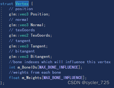
这里可以用LearnOpenGL的代码,把assimp中模型的顶点信息都存储到VBO里面了,并且帮我们绑定到VAO中了,我们只需要在着色器按照顺序获取数据即可。
一个顶点有如下的信息:
// render data
    unsigned int VBO, EBO;

    // initializes all the buffer objects/arrays
    void setupMesh()
    {
        // create buffers/arrays
        glGenVertexArrays(1, &VAO);
        glGenBuffers(1, &VBO);
        glGenBuffers(1, &EBO);

        glBindVertexArray(VAO);
        // load data into vertex buffers
        glBindBuffer(GL_ARRAY_BUFFER, VBO);
        // A great thing about structs is that their memory layout is sequential for all its items.
        // The effect is that we can simply pass a pointer to the struct and it translates perfectly to a glm::vec3/2 array which
        // again translates to 3/2 floats which translates to a byte array.
        glBufferData(GL_ARRAY_BUFFER, vertices.size() * sizeof(Vertex), &vertices[0], GL_STATIC_DRAW);

        glBindBuffer(GL_ELEMENT_ARRAY_BUFFER, EBO);
        glBufferData(GL_ELEMENT_ARRAY_BUFFER, indices.size() * sizeof(unsigned int), &indices[0], GL_STATIC_DRAW);

        // set the vertex attribute pointers
        // vertex Positions
        glEnableVertexAttribArray(0);
        glVertexAttribPointer(0, 3, GL_FLOAT, GL_FALSE, sizeof(Vertex), (void*)0);
        // vertex normals
        glEnableVertexAttribArray(1);
        glVertexAttribPointer(1, 3, GL_FLOAT, GL_FALSE, sizeof(Vertex), (void*)offsetof(Vertex, Normal));
        // vertex texture coords
        glEnableVertexAttribArray(2);
        glVertexAttribPointer(2, 2, GL_FLOAT, GL_FALSE, sizeof(Vertex), (void*)offsetof(Vertex, TexCoords));
        // vertex tangent
        glEnableVertexAttribArray(3);
        glVertexAttribPointer(3, 3, GL_FLOAT, GL_FALSE, sizeof(Vertex), (void*)offsetof(Vertex, Tangent));
        // vertex bitangent
        glEnableVertexAttribArray(4);
        glVertexAttribPointer(4, 3, GL_FLOAT, GL_FALSE, sizeof(Vertex), (void*)offsetof(Vertex, Bitangent));
		// ids
		glEnableVertexAttribArray(5);
		glVertexAttribIPointer(5, 4, GL_INT, sizeof(Vertex), (void*)offsetof(Vertex, m_BoneIDs));

		// weights
		glEnableVertexAttribArray(6);
		glVertexAttribPointer(6, 4, GL_FLOAT, GL_FALSE, sizeof(Vertex), (void*)offsetof(Vertex, m_Weights));
        glBindVertexArray(0);
    }
这里也帮我们绑定了贴图文件,对应的命名规则要按照这里来:比如texture_diffuse+num
    void Draw(Shader &shader)
    {
        // bind appropriate textures
        unsigned int diffuseNr  = 1;
        unsigned int specularNr = 1;
        unsigned int normalNr   = 1;
        unsigned int heightNr   = 1;
        for(unsigned int i = 0; i < textures.size(); i++)
        {
            glActiveTexture(GL_TEXTURE0 + i); // active proper texture unit before binding
            // retrieve texture number (the N in diffuse_textureN)
            string number;
            string name = textures[i].type;
            if(name == "texture_diffuse")
                number = std::to_string(diffuseNr++);
            else if(name == "texture_specular")
                number = std::to_string(specularNr++); // transfer unsigned int to string
            else if(name == "texture_normal")
                number = std::to_string(normalNr++); // transfer unsigned int to string
             else if(name == "texture_height")
                number = std::to_string(heightNr++); // transfer unsigned int to string

            // now set the sampler to the correct texture unit
            glUniform1i(glGetUniformLocation(shader.ID, (name + number).c_str()), i);
            // and finally bind the texture
            glBindTexture(GL_TEXTURE_2D, textures[i].id);

            // TODO : Pass tangential space data to shaders
        }

        // draw mesh
        glBindVertexArray(VAO);
        glDrawElements(GL_TRIANGLES, static_cast<unsigned int>(indices.size()), GL_UNSIGNED_INT, 0);
        glBindVertexArray(0);

        // always good practice to set everything back to defaults once configured.
        glActiveTexture(GL_TEXTURE0);
    }
3.2 顶点着色器
按照布局顺序获取顶点信息,然后求出TBN矩阵,并把所有位置信息转换到切线空间。
#version 330 core
layout (location = 0) in vec3 aPos;
layout (location = 1) in vec3 aNormal;
layout (location = 2) in vec2 aTexCoords;
layout (location = 3) in vec3 aTangent;
//layout (location = 4) in vec3 aBitTangent;

out vec3 tFragPos;
out vec2 texCoords;
out vec3 tViewPos;
out vec3 tLightPos;

uniform vec3 viewPos;
uniform vec3 lightPos;

uniform mat4 model;
uniform mat4 view;
uniform mat4 projection;

void main()
{
    gl_Position = projection * view * model * vec4(aPos,1.0f);
    texCoords = aTexCoords;
    // calculate TBN
    mat3 normalMatrix = transpose(inverse(mat3(model)));
    vec3 T = normalize(normalMatrix * aTangent);
    vec3 N = normalize(normalMatrix * aNormal);
    T = normalize(T - dot(T,N) * N);        //Gram-Schmidt process
    vec3 B = normalize(cross(T,N));

    mat3 TBN = transpose(mat3(T,B,N));            //the transpose and inverse is the same

    tFragPos = TBN * vec3(model * vec4(aPos,1.0f)); // this should be in tangent space
    tViewPos = TBN * viewPos;
    tLightPos = TBN * lightPos;
}
注意mat3(T,B,N)是按照列排,需要转置。然后BitTangent是没必要的,否则不能保证正交化。
3.3 片元着色器
只要所有向量在切线空间计算即可,注意命名规则,这里用的是Blinn-phong光照模型+光线衰减。
#version 330 core

in vec2 texCoords;
in vec3 tFragPos;
in vec3 tViewPos;
in vec3 tLightPos;

uniform vec3 lightColor;
uniform float lightLinear;
uniform float lightQuadratic;

uniform sampler2D texture_diffuse1;
uniform sampler2D texture_specular1;
uniform sampler2D texture_normal1;
//uniform sampler2D texture_height1;

out vec4 fragColor;
void main()
{
    vec3 Normal = texture(texture_normal1, texCoords).rgb;

    Normal = normalize(Normal * 2 - 1.0f) * 1.06f;

    vec3 Diffuse = texture(texture_diffuse1, texCoords).rgb;
    float specStrength = texture(texture_specular1,texCoords).r;

    // then calculate lighting as usual
    vec3 ambient = vec3(0.3 * Diffuse);
    vec3 lighting  = ambient;
    vec3 viewDir  = normalize(tViewPos - tFragPos);
    // diffuse
    vec3 lightDir = normalize(tLightPos - tFragPos);
    vec3 diffuse = max(dot(Normal, lightDir), 0.0) * Diffuse * lightColor;
    // specular
    vec3 halfwayDir = normalize(lightDir + viewDir);
    float spec = pow(max(dot(Normal, halfwayDir), 0.0), 32.0);
    vec3 specular = lightColor * spec * 0.1f;

    // attenuation
    float distance = length(tLightPos - tFragPos);
    float attenuation = 1.0 / (1.0 + lightLinear * distance + lightQuadratic * distance * distance);
    diffuse *= attenuation;
    specular *= attenuation;
    lighting += diffuse + specular;

    fragColor = vec4(lighting , 1.0f);
}
注意的是,法线需要转换到【-1,1】,否则不应该高光的地方会出现,高光部分会非常明显。
最后得到的效果应该如下所示:
