临摹对象
sfbus_demo
模型简介
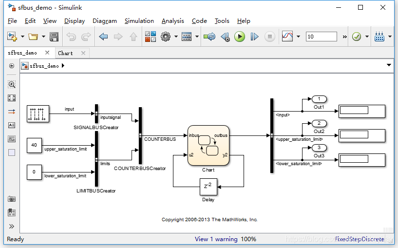
先看一下整体外观:
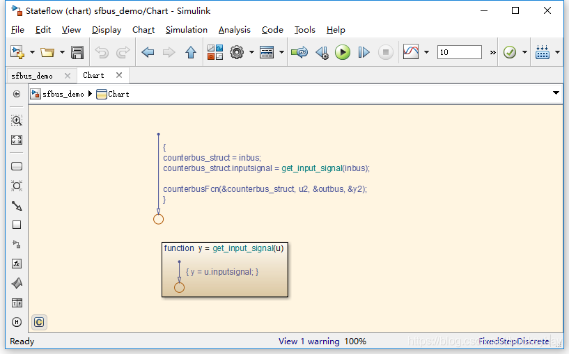
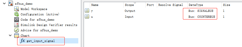
再看看stateflow的chart:
功能说明
重点在于,stateflow中能使用总线信号作为输入。图形函数的参数可以设置数据类型。
重要步骤
1,PreLoadFcn的回调函数中,要加载bus_objects:
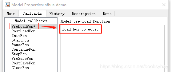
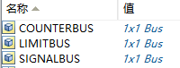
加载后,工作区中会有这3个总线的定义:
2,设置输入、输出和局部变量的数据类型为总线型:
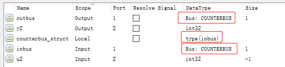
3,设置图形函数的输入输出变量的数据类型为总线(SIGNALBUS, COUNTERBUS)
4,在Simulation Target的配置中,添加头文件(#include "counterbus.h")和C文件(counterbus.c)
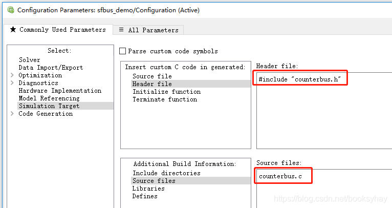
这两个文件里面定义了总线所对应的结构体,以及counterbusFcn函数。
counterbus.h头文件:
#ifndef _COUNTER_BUS_H_
#define _COUNTER_BUS_H_

#include "rtwtypes.h"

typedef struct {
  int input;
} SIGNALBUS;

typedef struct {
  int upper_saturation_limit;
  int lower_saturation_limit;
} LIMITBUS;

typedef struct {
  SIGNALBUS inputsignal;
  LIMITBUS limits;
} COUNTERBUS;

extern void counterbusFcn(COUNTERBUS *u1, int u2, COUNTERBUS *y1, int *y2);

#endif
counterbus.c文件:
#include "counterbus.h"

void counterbusFcn(COUNTERBUS *u1, int32_T u2, COUNTERBUS *y1, int32_T *y2)
{
  int32_T limit;
  boolean_T inputGElower;

  limit = u1->inputsignal.input + u2;

  inputGElower = (limit >= u1->limits.lower_saturation_limit);

  if((u1->limits.upper_saturation_limit >= limit) && inputGElower) {
    *y2 = limit;
  } else {

    if(inputGElower) {
      limit = u1->limits.upper_saturation_limit;
    } else {
      limit = u1->limits.lower_saturation_limit;
    }
    *y2 = limit;
  }

  y1->inputsignal.input = *y2;
  y1->limits = u1->limits;

}
参考资料
Integrate Custom Structures in Stateflow Charts
https://ww2.mathworks.cn/help/stateflow/ug/integrating-custom-structures-in-stateflow-charts.html
Access Bus Signals Through Stateflow Structures
https://ww2.mathworks.cn/help/stateflow/ug/about-stateflow-structures.html