图1.10对该问题进行了描述。
Figure 1.10 illustrates the problem.
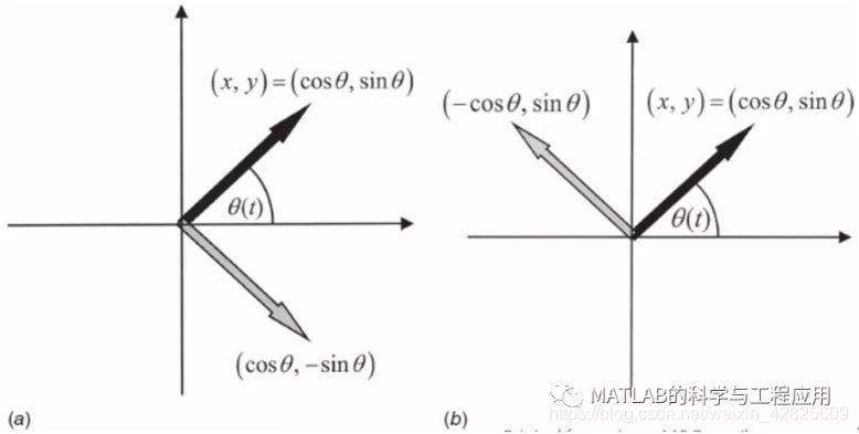
图1.10 (a)图1.9中接收机的I通道只测量相位θ(t) 的余弦值;(b)Q通道只测量相位θ(t) 的正弦值。(a) The Ichannel of the receiver in Fig. 1.9 measures only the cosine of the phasorθ(t). (b) The Q channel measures only the sine of the phasor
考虑图1.10a中的情况。
Consider the case shown in Fig. 1.10a.
信号相位θ(t)表示为复平面中的实心黑色相量。
The signal phase θ(t) is represented as asolid black phasor in the complex plane.
如果接收机中只有I通道,那么只能测量θ(t)的余弦值。
If only the I channel is implemented in thereceiver, only the cosine of θ(t) will be measured.
这样真实的相量就不能与图中的灰色向量–θ(t)进行区分了。
In this case, the true phasor will beindistinguishable from the gray phasor –θ(t).
类似地,如果接收机中只有Q通道,那么只能测量出θ(t)的正弦值,也就无法区分真实向量与灰色向量π – θ(t)。
Similarly, if only the Q channel isimplemented so that only the sine of θ(t) is measured, then the true phasorwill be indistinguishable from the gray phasor of Fig. 1.10b, which correspondsto π – θ(t).
当I和Q通道同时存在时,才能明确地确定相量所在的象限区间。
When both the I and Q channels areimplemented, the phasor quadrant is determined unambiguously.
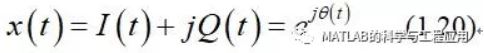
事实上,信号处理器通常将I信号指定为复信号的实部,将Q信号指定为虚部,从而构成复信号
In fact, the signal processor will normallyassign the I signal to be the real part of a complex signal and the Q signal tobe the imaginary part, forming a single complex signal
式(1.20)以一种更直观的方式表明了理想的相干接收机对发射信号的影响。
Equation (1.20) implies a more convenientway of representing the effect of an ideal coherent receiver on a transmittedsignal.
通常将发射信号的正弦波形式替换为等效的复指数形式。
Instead of representing the transmittedsignal by a sine function, an equivalent complex exponential function is usedinstead.
那么,式(1.17)的回波信号可以替换为
The echo signal of (1.17) is thus replacedby
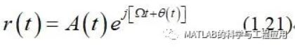
图1.9的接收机结构则替换为图1.11中的简化模型,其中回波信号通过与参考本振exp(– jΩt)进行复乘解调。
The receiver structure of Fig. 1.9 is thenreplaced with the simplified model of Fig. 1.11, where the echo is demodulatedby multiplication with a complex reference oscillator exp(– jΩt).
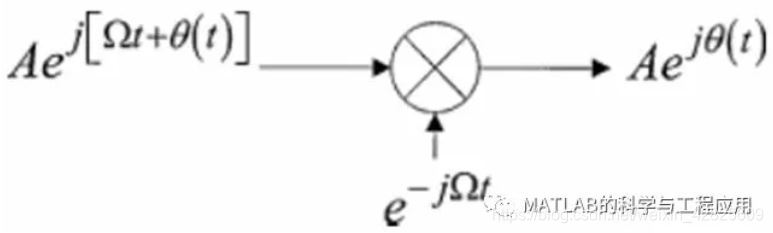
Figure 1.11. 使用复指数信号的简化接收机模型Simplified transmission and receiver model using complex exponentialsignals.
这种假设为复发射信号和复解调器的模型能够准确地获得式(1.20)的结果,并明确地模拟了接收机的I、Q通道,但表达形式更加简单、紧凑。
This technique of assuming a complextransmitted signal and corresponding complex demodulator produces exactly thesame result obtained in Eq. (1.20) by explicitly modeling the real-valuedsignals and the I and Q channels, but is much simpler and more compact.
本书以后的部分都将采用复指数的分析方法。
This complex exponential analysis approachis used throughout the remainder of the book.
重要的是要记住,这只是一种分析的方法;实际的模拟硬件设计仍然必须使用实值信号进行处理。
It is important to remember that this is ananalysis technique; actual analog hardware must still operate with real-valuedsignals only.
然而,一旦信号被数字化,就可以在数字处理器中被明确地视为复信号。
However, once signals are digitized, theymay be treated explicitly as complex signals in the digital processor.
——本文译自Mark A. Richards所著的《Fundamentals of Radar Signal Processing(Second edition)》
更多精彩文章请关注微信号: