参考:PG201 AXI DMA v7.1 AXI IP核
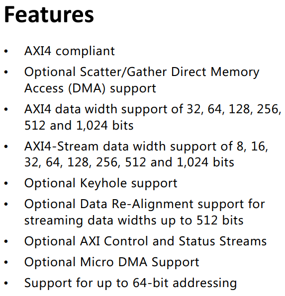
功能:一旦处理器配置好传输方式之后,DMA可以自己完成内存数据的搬进或者搬出,而不需要处理器的介入。如果使用方法得当,DMA可以显著地提高系统性能。
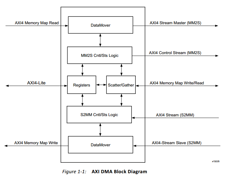
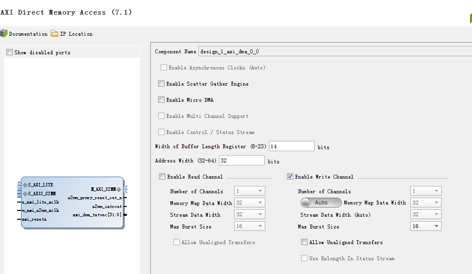
AXIDMA IP有6个接口,S_AXI_LITE是ARM配置dma寄存器的接口,M_AXI_SG是从(往)存储器加载(上传)buffer descriptor的接口,剩下4个构成两对接口,S2MM和MM2S表示数据的方向,AXI是存储器一侧的接口,AXIS是FPGA一侧的接口。AXIDMA IP和ARM自带的DMA是很像的,只不过不具备从存储器到存储器的功能,当然啦如果将S2MM和MM2S的AXIS接口直接连接也是可以实现的。
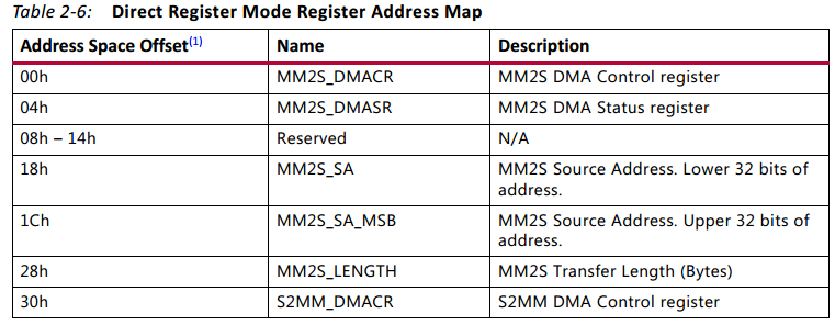
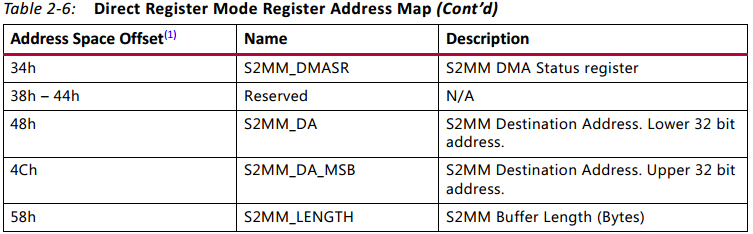
AXIDMA工作模式分为两种,分别是Direct Register Mode和Scatter/Gather Mode。Direct Register Mode具备DMA的基本功能,除了控制寄存器和状态寄存器之外,给出源(目的)地址和传输长度之后就可以开启一次传输了。Direct Register Mode的特点(也是缺点)是配置完一次寄存器之后只能完成存储器连续地址空间的读写,如果有需求往不同地址空间搬运数据的话,那就需要重新配置寄存器开启一次新的传输。
鉴于Direct Register Mode的不足,发展出了Scatter/Gather Mode,其工作方式要复杂得多。Scatter/Gather Mode把关于传输的基本参数(比如起始地址、传输长度、包信息等)存储在存储器中,一套参数称之为Buffer Descriptor(简称BD),在工作过程中通过上面提到的SG接口来加载BD并且更新BD中的状态。从图3可以看出,Scatter/Gather Mode下的寄存器列表中没有了Address、Length相关的寄存器了,取而代之的是CURDESC、TAILDESC。
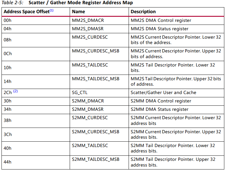
MM2S_DMACR


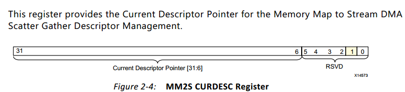
AXIDMA启动后,首先从CURDESC指定的位置加载BD,完成当前BD的传输任务后根据BD链条找到下一个BD,依次完成BD指定的传输,直到遇到TAILDESC指定的BD才停止。
Multichannel DMA:在Scatter/Gather Mode下S2MM和MM2S都支持多个通道,Direct Register Mode不支持多通道。如图5所示,多通道相比非多通道,BD中增加了TID和TDEST,用来区分不同的通道。
Data Cache:从图9中可以看出,在ZYNQ内部ARM CPU与DDR3之间存在两级缓存区,分别是L1 I/D Cache和L2 Cache,它们都是32-byte line size。Data Cache的使用带来了一个问题,DMA和CPU都与DDR3有数据往来,可CPU的Cache是不知道DMA对DDR3的数据读写过程的,也就是说CPU得到的数据很可能是”假的“,这就是著名的Cache一致性问题。解决该问题的办法是在程序中使用flush函数(invalid函数)及时将Cache的数据写入到DDR3(从DDR3读取数据到Cache),也就是说要避免该问题就只能靠我们自己了。
Programming Sequence :
Direct Register Mode(Simple DMA)A DMA operation for the MM2S channel is set up and started by the following sequence :
1. Start the MM2S channel running by setting the run/stop bit to 1 (MM2S_DMACR.RS =
1). The halted bit (DMASR.Halted) should deassert indicating the MM2S channel is
running
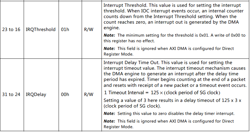
2. If desired, enable interrupts by writing a 1 to MM2S_DMACR.IOC_IrqEn and
MM2S_DMACR.Err_IrqEn. The delay interrupt, delay count, and threshold count are not
used when the AXI DMA is configured for Direct Register Mode.
3. Write a valid source address to the MM2S_SA register. If AXI DMA is configured for an
address space greater than 32, then program the MM2S_SA MSB register. If the AXI DMA
is not configured for Data Re-Alignment, then a valid address must be aligned or
undefined results occur. What is considered aligned or unaligned is based on the stream
data width. When AXI_DMA is configured in Micro Mode, it is your responsibility to
specify the correct address. Micro DMA does not take care of the 4K boundary.
For example, if Memory Map Data Width = 32, data is aligned if it is located at word
offsets (32-bit offset), that is 0x0, 0x4, 0x8, 0xC, and so forth. If DRE is enabled and
Streaming Data Width < 128, then the Source Addresses can be of any byte offset.
4. Write the number of bytes to transfer in the MM2S_LENGTH register. A value of zero
written has no effect. A non-zero value causes the MM2S_LENGTH number of bytes to
be read on the MM2S AXI4 interface and transmitted out of the MM2S AXI4-Stream
interface. The MM2S_LENGTH register must be written last. All other MM2S registers
can be written in any order. In the case of Micro DMA, this value cannot exceed
[Burst_length * (Memory Mapped Data Width)/8].
A DMA operation for the S2MM channel is set up and started by the following sequence:
1. Start the S2MM channel running by setting the run/stop bit to 1 (S2MM_DMACR.RS =
1). The halted bit (DMASR.Halted) should deassert indicating the S2MM channel is
running.
2. If desired, enable interrupts by writing a 1 to S2MM_DMACR.IOC_IrqEn and
S2MM_DMACR.Err_IrqEn. The delay interrupt, delay count, and threshold count are not
used when the AXI DMA is configured for Direct Register Mode.
3. Write a valid destination address to the S2MM_DA register. If AXI DMA is configured for
an address space greater than 32, program the S2MM_DA MSB register.
4. If the AXI DMA is not configured for Data Re-Alignment then a valid address must be
aligned or undefined results occur. What is considered aligned or unaligned is based on
the stream data width
5. Write the length in bytes of the receive buffer in the S2MM_LENGTH register. A value of
zero has no effect. A non-zero value causes a write on the S2MM AXI4 interface of the
number of bytes received on the S2MM AXI4-Stream interface. A value greater than or
equal to the largest received packet must be written to S2MM_LENGTH. A receive buffer
length value that is less than the number of bytes received produces undefined results.
When AXI DMA is configured in Micro mode, this value should exactly match the bytes
received on the S2MM AXI4-Stream interface. The S2MM_LENGTH register must be
written last. All other S2MM registers can be written in any order