机器视觉课内实验:一种摄像机标定算法的编程实现
工具箱toolbox_calib:http://www.vision.caltech.edu/bouguetj/calib_doc/download/index.html
参考资料及图片来源:http://www.vision.caltech.edu/bouguetj/calib_doc/htmls/example.html
在MATLAB中添加工具箱及图片方法:https://blog.csdn.net/lyc_daniel/article/details/23678979
一 .实验目的
掌握摄像机标定方法的原理,采用一种摄像机标定算法,编程实现摄像机内部参数和外部参数的估计。
二.标定原理
摄像机标定是指建立摄像机图像像素位置与场景点位置之间的关系,其途径是根据摄像机模型,由已知特征点的图像坐标和世界坐标求解摄像机的模型参数。
三.实验步骤及截图
采用张正友摄像机标定算法,具体步骤如下:
1、采集图像:采集的图像统一命名后,拷贝到toolbox_calib目录中。
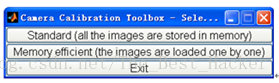
2、在Matlab命令窗口运行calib_gui指令,然后选择第一项
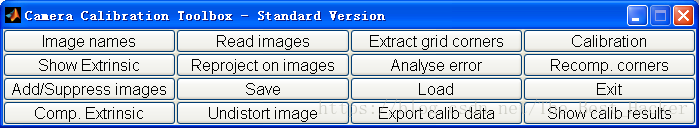
3、阅读图片,点击“Image names”键,在Matlab命令窗口分别输入Image和图像格式t
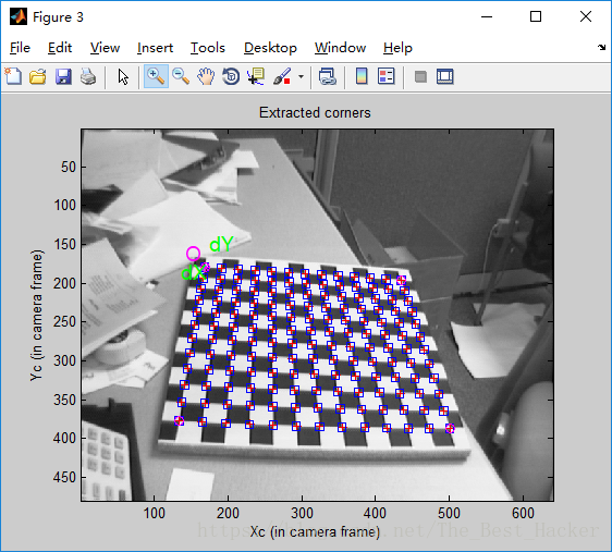
4、提取网格角点。
5、主要校准步骤: 点击Calibration来运行主要的摄像机校准程序。
6、点击Reproject on images将网格重新投影到原始图像上。这些投影是根据当前的内、外部参数计算的。
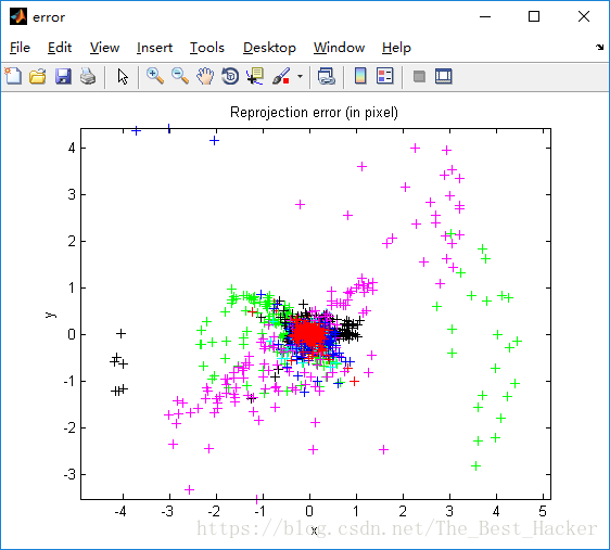
7、重投影误差也以颜色编码的十字架的形式显示:
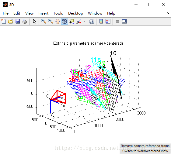
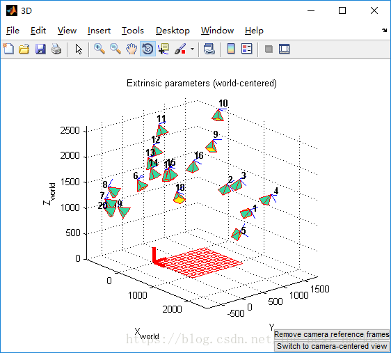
8、Show Extrinsic外部参数(网格相对于照相机的相对位置)然后以3D图的形式显示若要从“以摄像机为中心”视图切换到“以世界为中心”视图,点击Switch to world-centered view
四.程序代码
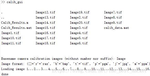
>> calib_gui
. Image10.tif Image13.tif Image16.tif Image19.tif Image3.tif Image6.tif Image9.tif
.. Image11.tif Image14.tif Image17.tif Image2.tif Image4.tif Image7.tif
Image1.tif Image12.tif Image15.tif Image18.tif Image20.tif Image5.tif Image8.tif
Basename camera calibration images (without number nor suffix):
. Image10.tif Image13.tif Image16.tif Image19.tif Image3.tif Image6.tif Image9.tif
.. Image11.tif Image14.tif Image17.tif Image2.tif Image4.tif Image7.tif
Image1.tif Image12.tif Image15.tif Image18.tif Image20.tif Image5.tif Image8.tif
Basename camera calibration images (without number nor suffix): Image
Image format: ([]='r'='ras', 'b'='bmp', 't'='tif', 'p'='pgm', 'j'='jpg', 'm'='ppm') t
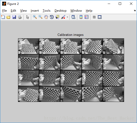
Loading image 1...2...3...4...5...6...7...8...9...10...11...12...13...14...15...16...17...18...19...20...
done
Extraction of the grid corners on the images
Number(s) of image(s) to process ([] = all images) =
Window size for corner finder (wintx and winty):
wintx ([] = 5) =
winty ([] = 5) =
Window size = 11x11
Do you want to use the automatic square counting mechanism (0=[]=default)
or do you always want to enter the number of squares manually (1,other)?
Processing image 1...
Using (wintx,winty)=(5,5) - Window size = 11x11 (Note: To reset the window size, run script clearwin)
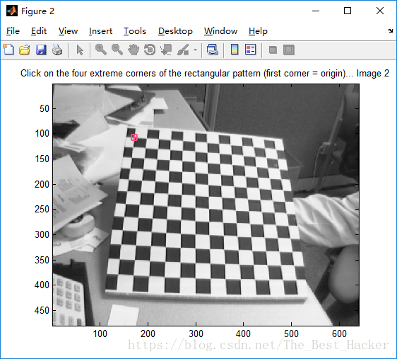
Click on the four extreme corners of the rectangular complete pattern (the first clicked corner is the origin)...
Size dX of each square along the X direction ([]=100mm) = 100
Size dY of each square along the Y direction ([]=100mm) = 100
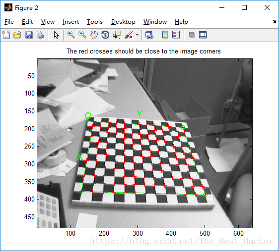
If the guessed grid corners (red crosses on the image) are not close to the actual corners,
it is necessary to enter an initial guess for the radial distortion factor kc (useful for subpixel detection)
Need of an initial guess for distortion? ([]=no, other=yes)
Corner extraction...
Processing image 2...
%此处省率从图2——图19的分析
Processing image 20...
Using (wintx,winty)=(5,5) - Window size = 11x11 (Note: To reset the window size, run script clearwin)
Click on the four extreme corners of the rectangular complete pattern (the first clicked corner is the origin)...
Size of each square along the X direction: dX=100mm
Size of each square along the Y direction: dY=100mm (Note: To reset the size of the squares, clear the variables dX and dY)
If the guessed grid corners (red crosses on the image) are not close to the actual corners,
it is necessary to enter an initial guess for the radial distortion factor kc (useful for subpixel detection)
Need of an initial guess for distortion? ([]=no, other=yes)
Corner extraction...
done
Aspect ratio optimized (est_aspect_ratio = 1) -> both components of fc are estimated (DEFAULT).
Principal point optimized (center_optim=1) - (DEFAULT). To reject principal point, set center_optim=0
Skew not optimized (est_alpha=0) - (DEFAULT)
Distortion not fully estimated (defined by the variable est_dist):
Sixth order distortion not estimated (est_dist(5)=0) - (DEFAULT) .
Initialization of the principal point at the center of the image.
Initialization of the intrinsic parameters using the vanishing points of planar patterns.
Initialization of the intrinsic parameters - Number of images: 20
Calibration parameters after initialization:
Focal Length: fc = [ 670.65485 670.65485 ]
Principal point: cc = [ 319.50000 239.50000 ]
Skew: alpha_c = [ 0.00000 ] => angle of pixel = 90.00000 degrees
Distortion: kc = [ 0.00000 0.00000 0.00000 0.00000 0.00000 ]
Main calibration optimization procedure - Number of images: 20
Gradient descent iterations: 1...2...3...4...5...6...7...8...9...10...11...12...13...14...15...16...17...18...19...20...21...22...23...24...done
Estimation of uncertainties...done
Calibration results after optimization (with uncertainties):
Focal Length: fc = [ 662.49524 664.67734 ] +/- [ 1.43401 1.54262 ]
Principal point: cc = [ 306.51284 241.75114 ] +/- [ 2.83486 2.60830 ]
Skew: alpha_c = [ 0.00000 ] +/- [ 0.00000 ] => angle of pixel axes = 90.00000 +/- 0.00000 degrees
Distortion: kc = [ -0.27907 0.32025 0.00050 0.00028 0.00000 ] +/- [ 0.01144 0.04729 0.00064 0.00067 0.00000 ]
Pixel error: err = [ 0.59063 0.42184 ]
Note: The numerical errors are approximately three times the standard deviations (for reference).
Number(s) of image(s) to show ([]= all images)=
Invalid image format
Image format: ([]='r'='ras', 'b'='bmp', 't'='tif', 'p'='pgm', 'j'='jpg', 'm'='ppm') Number(s) of image(s) to show ([] = all images) = Number(s) of image(s) to show ([] = all images) =
Pixel error: err = [0.59063 0.42184] (all active images)
五 .实验心得
在本次实验中我将前面课堂上所讲的摄像机的标定成功的通过编程实现了,在本次实验当中应用了张正友平面标定的方法去作为编程的算法基础,实验要求通过MATLAB进行结果实现,但由于长时间没有用过,所以在本次实验中查资料占据了我很多时间。在实验之前,我查了好多关于张正友摄像机标定算法,感觉实现这此实验对我来说还是很不容易的。感觉理论和实践还是相差甚远。