之前有篇博文讲了半带FIR滤波器:半带FIR滤波器
其幅频响应如下:
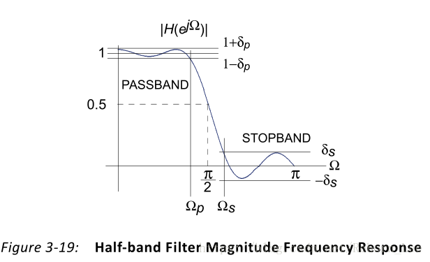
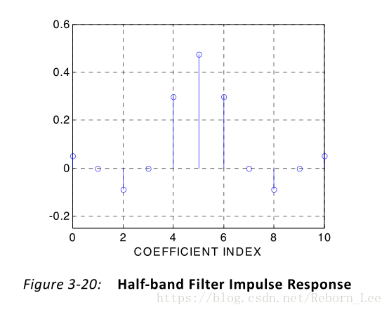
脉冲响应如下:
而今天所要讲的是半带抽取器,半带抽取器是一个多相滤波器,它嵌入了输入信号的2- 1下采样。图3-30显示了结构。
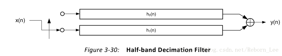
该滤波器与多相抽取器中描述的多相抽取器非常相似,抽取因子设置为M=2。但是,当频率响应反映出真正的半带特性时,在实现上有细微的差别,这使得半带抽取器成为一个更有效的2比1下采样滤波器。
多相抽取器博文:多相抽取器
Figure 3-30 details a 7-tap half-band polyphase filter when the coefficients are allocated to the two polyphase segments and
shown in Figure 3-30.
图3-30详细介绍了当系数分配给两个多相段和
时的7抽头半带多相滤波器,如图3-30所示。
Figure 3-31 (a) is the filter impulse response ( ). Figure 3-31 (b) provides a detailed illustration of the polyphase subfilters and shows how the filter coefficients are allocated to the two polyphase arms.
图3-31(a)是滤波器脉冲响应()。 图3-31(b)提供了多相子滤波器的详细说明,并显示了滤波器系数如何分配给两个多相臂。
In the bottom arm, the only non-zero coefficient, is the center value of the impulse response Figure 3-31 (c) shows the optimized architecture when the redundant multipliers and adders are removed. The final structure has a reduced computation workload in contrast to a more general 2:1 down-sampling filter.
在底臂中,唯一的非零系数是脉冲响应的中心值。图3-31(c)显示了移除冗余乘法器和加法器时的优化架构。 与更通用的2:1下采样滤波器相比,最终结构具有减少的计算工作量。
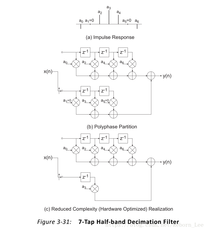
The number of multiply-accumulate (MAC) operations required to compute an output sample has been lowered by a factor of approximately two. In this figure, the high density of zero-valued filter coefficients is exploited in the FPGA realization to produce a minimal area implementation.
计算输出样本所需的乘法累加(MAC)操作的数量已降低了大约两倍。 在该图中,在FPGA实现中利用高密度零值滤波器系数来产生最小面积实现。