本文将针对STML152的IAP移植过程作一个笔记。
首先得下载AN3310的示例代码,地址为:http://www.st.com/content/st_com/en/products/embedded-software/mcus-embedded-software/stm32-embedded-software/stm32-standard-peripheral-libraries-expansions/stsw-stm32075.html
下载完成后,我们需要做些修改,我们将在NUCLEO-L152RE板子上进行验证测试。
由于NUCLEO-L152RE板子默认MCU是没有外挂晶振的,但可以通过ByPass方式使用ST-LInk的8M晶振,但这里只是作为IAP,且只需要使用到串口,因此可以只使用HSI,于是,在AN3310的工程中打开system_stm32l1xx.c文件找到SystemInit函数,注释掉//SetSysClock();,让系统使用默认的HSI即可。
void SystemInit (void)
{
  /*!< Set MSION bit */
  RCC->CR |= (uint32_t)0x00000100;

  /*!< Reset SW[1:0], HPRE[3:0], PPRE1[2:0], PPRE2[2:0], MCOSEL[2:0] and MCOPRE[2:0] bits */
  RCC->CFGR &= (uint32_t)0x88FFC00C;

  /*!< Reset HSION, HSEON, CSSON and PLLON bits */
  RCC->CR &= (uint32_t)0xEEFEFFFE;

  /*!< Reset HSEBYP bit */
  RCC->CR &= (uint32_t)0xFFFBFFFF;

  /*!< Reset PLLSRC, PLLMUL[3:0] and PLLDIV[1:0] bits */
  RCC->CFGR &= (uint32_t)0xFF02FFFF;

  /*!< Disable all interrupts */
  RCC->CIR = 0x00000000;

#ifdef DATA_IN_ExtSRAM
  SystemInit_ExtMemCtl();
#endif /* DATA_IN_ExtSRAM */

  /* Configure the System clock frequency, AHB/APBx prescalers and Flash settings */
  //SetSysClock();

#ifdef VECT_TAB_SRAM
  SCB->VTOR = SRAM_BASE | VECT_TAB_OFFSET; /* Vector Table Relocation in Internal SRAM. */
#else
  SCB->VTOR = FLASH_BASE | VECT_TAB_OFFSET; /* Vector Table Relocation in Internal FLASH. */
#endif
}
然后修改man.c文件中的main函数,注释掉一些按键,让程序默认进入到升级模式:
int main(void)
{
  /* Unlock the Flash Program Erase controller */
  FLASH_If_Init();

  /* Initialize Key Button mounted on STM32L15xx-EVAL board */
  //STM_EVAL_PBInit(BUTTON_KEY, BUTTON_MODE_GPIO);

  /* Test if Key push-button on STM32L15xx-EVAL Board is pressed */
  //if (STM_EVAL_PBGetState(BUTTON_KEY) != 0x00)
  {
    /* Execute the IAP driver in order to reprogram the Flash */
    IAP_Init();
    /* Display main menu */
    Main_Menu ();
  }
#if 0
  /* Keep the user application running */
  else
  {
    /* Test if user code is programmed starting from address "APPLICATION_ADDRESS" */
    if (((*(__IO uint32_t*)APPLICATION_ADDRESS) & 0x2FFE0000 ) == 0x20000000)
    {
      /* Jump to user application */
      JumpAddress = *(__IO uint32_t*) (APPLICATION_ADDRESS + 4);
      Jump_To_Application = (pFunction) JumpAddress;
      /* Initialize user application's Stack Pointer */
      __set_MSP(*(__IO uint32_t*) APPLICATION_ADDRESS);
      Jump_To_Application();
    }
  }
#endif
  while (1)
  {}
}
由于NUCLEO板子默认使用的是USART2,因此需要修改使用的串口:
void IAP_Init(void)
{
 USART_InitTypeDef USART_InitStructure;
  /* USART resources configuration (Clock, GPIO pins and USART registers) ----*/
  /* USART configured as follow:
        - BaudRate = 115200 baud
        - Word Length = 8 Bits
        - One Stop Bit
        - No parity
        - Hardware flow control disabled (RTS and CTS signals)
        - Receive and transmit enabled
  */
  USART_InitStructure.USART_BaudRate = 115200;
  USART_InitStructure.USART_WordLength = USART_WordLength_8b;
  USART_InitStructure.USART_StopBits = USART_StopBits_1;
  USART_InitStructure.USART_Parity = USART_Parity_No;
  USART_InitStructure.USART_HardwareFlowControl = USART_HardwareFlowControl_None;
  USART_InitStructure.USART_Mode = USART_Mode_Rx | USART_Mode_Tx;

  //STM_EVAL_COMInit(COM2, &USART_InitStructure);
  USART2_Init(&USART_InitStructure);
}
USART2_Init()函数为新添加的串口初始化函数,其定义如下:
void USART2_Init(USART_InitTypeDef* USART_InitStruct)
{
  GPIO_InitTypeDef GPIO_InitStructure;

  /* Enable GPIO clock */
  RCC_AHBPeriphClockCmd(RCC_AHBPeriph_GPIOA, ENABLE);

  /* Enable UART clock */
  RCC_APB1PeriphClockCmd(RCC_APB1Periph_USART2, ENABLE);

  /* Connect PXx to USARTx_Tx */
  GPIO_PinAFConfig(GPIOA, GPIO_PinSource2, GPIO_AF_USART2);

  /* Connect PXx to USARTx_Rx */
  GPIO_PinAFConfig(GPIOA, GPIO_PinSource3, GPIO_AF_USART2);

  /* Configure USART Tx as alternate function push-pull */
  GPIO_InitStructure.GPIO_Pin = GPIO_Pin_2|GPIO_Pin_3;
  GPIO_InitStructure.GPIO_Mode = GPIO_Mode_AF;
  GPIO_InitStructure.GPIO_Speed = GPIO_Speed_40MHz;
  GPIO_InitStructure.GPIO_OType = GPIO_OType_PP;
  GPIO_InitStructure.GPIO_PuPd = GPIO_PuPd_UP;
  GPIO_Init(GPIOA, &GPIO_InitStructure);

  /* Configure USART Rx as alternate function push-pull */
  //GPIO_InitStructure.GPIO_Pin = COM_RX_PIN[COM];
  //GPIO_Init(COM_RX_PORT[COM], &GPIO_InitStructure);

  /* USART configuration */
  USART_Init(USART2, USART_InitStruct);

  /* Enable USART */
  USART_Cmd(USART2, ENABLE);
}
接下来需要修改程序中使用到的打印函数:
void SerialPutChar(uint8_t c)
{
  USART_SendData(USART2, c);
  while (USART_GetFlagStatus(USART2, USART_FLAG_TXE) == RESET)
  {
  }
}
uint32_t SerialKeyPressed(uint8_t *key)
{
if ( USART_GetFlagStatus(USART2, USART_FLAG_RXNE) != RESET)
{
*key = (uint8_t)USART2->DR;
return 1;
}
else
{
return 0;
}
}
基本上就移植好了,编译烧录进NUCLEO板中运行。
接下来需要找一个PC端软件超级终端。
由于我使用的是64位Windows7,默认是不带Hyper Terminal的,需要下载个:http://download.csdn.net/detail/crifan/3508497
我是下载的这个,是XP中带的那个,还不错吧。
除了IAP程序,我们还得准备APP程序,由于IAP支持烧录的是BIN文件,因此,我们得生成BIN文件,HEX是不行的。
在APP工程中我们得注意几项内容,以IAR为例:
1 在option->Linker下:
config->Edit..--->Vector Table 的起始地址改为:0x08003000
---->Memory Regions->ROM改为:0x08003000
2 option->Output Converter->修改生成BIN文件
3 sysytem_stm32l1xx.c文件下
找到宏定义
#define VECT_TAB_OFFSET 0x3000
偏移位置必须改为0x3000
到此基本可以了,APP就这样。
最后就是测试了。
测试:
首先得将IAP烧录进MCU,然后再通过IAP烧录APP。
通过IAP烧录APP过程如下:
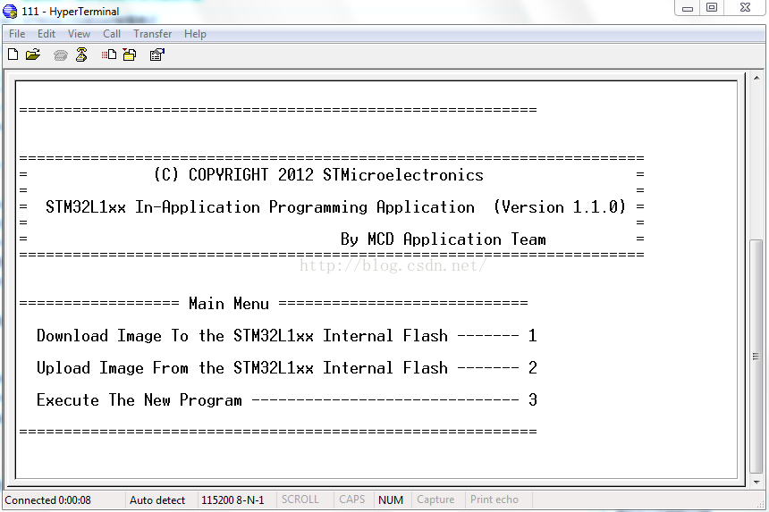
打开超级终端,连接上串口,有如下界面:
波特率:115200 data bis:8 parity:none stop bits:1 Flow control:none
通过键盘输入1:
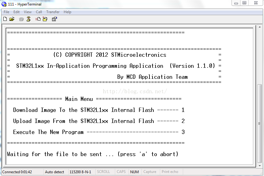
从菜单transfer->Send file打开如下界面,输入APP的BIN文件路径,并使用Ymodem传输协议,如下图:
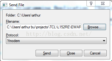
点击Send,开始烧录。。。

传输结束后,按下3,运行APP程序,至此,整个IAP与APP都可以正常工作了。
结束语:
这个只是个示例,实际IAP是还需要修改的,得判断是进行升级模式还是直接跳过进入APP,这个就需要看设计如何了。