最近写一个有关视频的项目,需要用到GLSurfaceView,先自己琢磨琢磨。
基础:
在Android平台上使用OpenGL ES主要有两种方式:NDK和SDK。通过NativeActivity,应用在native(c/c++)中管理整个activity的声明周期,以及绘制过程。由于爱native代码中,可以访问OpenGL ES的代码,因此,可以认为NativeActivity提供了一个OpenGL ES的运行环境。同时,Android提供了两个可以运行在OpenGL ES的类:GLSurfaceView和TextureView。由于真正的OpenGL ES仍然运行在native在层,因此在performance上,使用SDK并不比NDK差。而避免了JNI,客观上对于APP开发者来说使用SDK要比NDK容易。而GLSurfaceView和GLSurfaceView.Renderer是使用OpenGL ES的基础:
GLSurfaceView:
这个是我们使用OpenGL ES来进行绘制和操作的view,它和SurfaceView在功能上相似。GLSurfaceView.Renderer:
这个接口定义了在GLSurfaceView上绘制的方法,我们必须将它实例化attach到GLSurfaceView。- onSurfaceCreated():当创建GLSurfaceView时这个方法只会调用一次,可以在这里进行一些初始化的操作。
- onDrawFrame():每次重新draw SurfaceView的时候,就会调用这个方法。这个方法是绘制图像对象的主要方法。
- onSurfaceChange():当GLSurfaceView发生形状改变的时候,就会调用这个方法。
绘制图像的映射坐标:
OpenGL假定了一个正方形,统一坐标系,默认情况下,会将这些坐标绘制到典型不是方形的屏幕上,就好像它是正方形一样。

左边是OpenGL的坐标系,右边是在android屏幕上的展示
为了解决这个问题,我们可以使用OpenGL投影模式和Camera视角来转换坐标,以便图形对象在任何显示器上都有正确的比例。我们可以创建一个投影矩阵和一个Camera视图矩阵去应用到OpenGL 的渲染管线中。投影矩阵重新计算图像的坐标,以便它们正确地映射到Android屏幕。Camera视图矩阵会进行转换从特定的眼睛位置来渲染对象。
- 投影摄图:使用设备的几何形状去创建投影矩阵,以便重新计算对象坐标
public void onSurfaceChanged(GL10 gl, int width, int height) {
    gl.glViewport(0, 0, width, height);

    // make adjustments for screen ratio
    float ratio = (float) width / height;
    gl.glMatrixMode(GL10.GL_PROJECTION);        // set matrix to projection mode
    gl.glLoadIdentity();                        // reset the matrix to its default state
    gl.glFrustumf(-ratio, ratio, -1, 1, 3, 7);  // apply the projection matrix
}
2。Cemera转换矩阵: 使用投影矩阵调整坐标系后,还必须应用Camera视角。
public void onDrawFrame(GL10 gl) {
    ...
    // Set GL_MODELVIEW transformation mode
    gl.glMatrixMode(GL10.GL_MODELVIEW);
    gl.glLoadIdentity();                      // reset the matrix to its default state

    // When using GL_MODELVIEW, you must set the camera view
    GLU.gluLookAt(gl, 0, 0, -5, 0f, 0f, 0f, 0f, 1.0f, 0.0f);
    ...
}
Projection and camera view in OpenGL ES 2.0 and higher
在ES 2.0和3.0中,我们可以通过向图像对象的顶点着色器添加矩阵成员来应用投影和camera视角。通过矩阵成员的添加,我们可以生成并应用投影矩阵和camera矩阵到我们的对象中。
1. 添加矩阵到顶点着色器:为视图投影矩阵创建一个变量,并将其作为着色器的乘数,下面代码是顶点着色器的代码,允许我们应用投影和相机视图矩阵到使用着色器的对象坐标上的uMVPMatrix成员。
private final String vertexShaderCode =

    // This matrix member variable provides a hook to manipulate
    // the coordinates of objects that use this vertex shader.
    "uniform mat4 uMVPMatrix;   \n" +

    "attribute vec4 vPosition;  \n" +
    "void main(){               \n" +
    // The matrix must be included as part of gl_Position
    // Note that the uMVPMatrix factor *must be first* in order
    // for the matrix multiplication product to be correct.
    " gl_Position = uMVPMatrix * vPosition; \n" +

    "}  \n";
Note:上面的示例在定点着色器中定义了一个单一的转换矩阵成员,可以将其结合投影矩阵和相机视图矩阵应用。取决于你的应用程序所需,你可能想单独地在顶点着色器中声明投影矩阵和相机视图矩阵成员,以便可以独立的改变它们。
2.访问着色器矩阵:在顶点着色器创建一个hook(一个变量)之后,你就可以访问这个变量来应用投影和相机视图矩阵。下面的示例代码展示如何修改 GLSurfaceView.Renderer实现的onSurfaceCreated()方法,来访问如上定义在顶点着色器中矩阵变量。
public void onSurfaceCreated(GL10 unused, EGLConfig config) {
    ...
    muMVPMatrixHandle = GLES20.glGetUniformLocation(mProgram, "uMVPMatrix");
    ...
}
3.创建投影矩阵和camera矩阵
public void onSurfaceCreated(GL10 unused, EGLConfig config) {
    ...
    // Create a camera view matrix
    Matrix.setLookAtM(mVMatrix, 0, 0, 0, -3, 0f, 0f, 0f, 0f, 1.0f, 0.0f);
}

public void onSurfaceChanged(GL10 unused, int width, int height) {
    GLES20.glViewport(0, 0, width, height);

    float ratio = (float) width / height;

    // create a projection matrix from device screen geometry
    Matrix.frustumM(mProjMatrix, 0, -ratio, ratio, -1, 1, 3, 7);
}
4.应用投影矩阵和Camera矩阵:为了应用投影和相机视图转换,将两个矩阵相乘,然后将它们设置给顶点着色器,然后将它们应用于OpenGL渲染的图形对象
public void onDrawFrame(GL10 unused) {
    ...
    // Combine the projection and camera view matrices
    Matrix.multiplyMM(mMVPMatrix, 0, mProjMatrix, 0, mVMatrix, 0);

    // Apply the combined projection and camera view transformations
    GLES20.glUniformMatrix4fv(muMVPMatrixHandle, 1, false, mMVPMatrix, 0);

    // Draw objects
    ...
}
形状面和环绕(Shape Faces and Winding)
在OpenGL中,形状的表明由三维空间的三个点或以上定义而成。一组三个或更多的点(在OpenGL中叫顶点)具有正面和背面。那么怎么知道那一面是正面那一面是背面,我们可以使用环绕或定义点的方向。
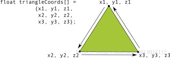
图中的坐标列表按逆时针绘制。
在例子中,三角形的点被定义在一个逆时针方向绘制的顺序中。绘制这些坐标的顺序定义了形状的环绕方向。在OpenGL中,默认逆时针绘制的面是正面,其他面试背面。
为什么要说正面呢,因为在OpenGL有一个常用的特性-面剔除。面剔除是OpenGL环境允许我们忽略图像的背面渲染管道,以这样来节省时间,内存和处理周期。
// enable face culling feature
gl.glEnable(GL10.GL_CULL_FACE);
// specify which faces to not draw
gl.glCullFace(GL10.GL_BACK);
选择OpenGL API版本(Choosing an OpenGL API Version)
OpenGL ES 1.0 API 版本(以及1.1的扩展),2.0版本以及3.0版本都为创建3D游戏,可视化UI提供了高性能的图形绘制接口。OpenGL ES 2.0和3.0的图形编程有很大的相似之处,3.0版本其实就是多了一些特性的2.0 版本集合库。OpenGL ES1.0/1.1的编程与OpenGL ES 2.0和3.0就相当的不同了,所以开发者在开始使用这些APIs开发之前应该仔细认真考虑如下的因素:
性能- 通常OpenGL ES 2.0和3.0都提供了比ES 1.0/1.1更快的图形性能。然而,由于不同的硬件厂商对OpenGL ES图形管道的实现,性能也因你运行OpenGL应用程序的Android设备而异。
设备兼容 - 开发者应该考虑设备的类型,Android的版本以及OpenGL ES的版本是否在他们的目标用户上有效。获取更多关于OpenGL跨设备兼容的内容,可参看上文。
代码的简便性 - OpenGL ES 1.0/1.1 API提供了稳定的功能管道和便利的功能,不过这些功能在OpenGL ES 2.0、3.0 APIs已经失效了。对OpenGL ES新手的开发人员可能会发现版本1.0 / 1.1的编码更快,更方便。
图形控制 - OpenGL ES 2.0和3.0 API通过使用着色器提供完全可编程的管道来提供更高程度的控制。通过更直接地控制图形处理管道,开发人员可以创建1.0 / 1.1 API很难生成的效果。
纹理支持 - OpenGL ES 3.0 API 拥有最好的纹理压缩支持,因为它保证了支持透明度的ETC2压缩格式的有效性。1.x和2.0 API的实现通常包含ETC1的支持,然而,纹理格式不支持透明度,所以你得针对设备提供的其他压缩格式资源。
原文链接:https://developer.android.google.cn/guide/topics/graphics/opengl.html
Displaying graphics with OpenGL
GLSurfaceView是容纳OpenGL图像的一种方式,对于满屏或接近满屏的图形,推介使用它。如果只是布局中的小一部分,推介使用TextureView。
可以使用GLSurfaceView作为主视图:
public class OpenGLES20Activity extends Activity {

    private GLSurfaceView mGLView;

    @Override
    public void onCreate(Bundle savedInstanceState) {
        super.onCreate(savedInstanceState);

        // Create a GLSurfaceView instance and set it
        // as the ContentView for this Activity.
        mGLView = new MyGLSurfaceView(this);
        setContentView(mGLView);
    }
}
GLSurfaceView是一个我们可以在这里画图像的view,但是画的过程是由GLSurfaceView.Renderer来控制的:
class MyGLSurfaceView extends GLSurfaceView {

    private final MyGLRenderer mRenderer;

    public MyGLSurfaceView(Context context){
        super(context);

        // Create an OpenGL ES 2.0 context
        setEGLContextClientVersion(2);

        mRenderer = new MyGLRenderer();

        // Set the Renderer for drawing on the GLSurfaceView
        setRenderer(mRenderer);
    }
}
还有一个选项是:
// Render the view only when there is a change in the drawing data
setRenderMode(GLSurfaceView.RENDERMODE_WHEN_DIRTY);只有调用requestRenderer()的时候,GLSurfaceView才会重画。
在Renderer中有三个方法是来弄清楚怎么在GLSurfaceView上画画的:
- onSurfaceCreated() - Called once to set up the view’s OpenGL ES environment.
- onDrawFrame() - Called for each redraw of the view.
- onSurfaceChanged() - Called if the geometry of the view changes, for example when the device’s screen orientation changes.
public class MyGLRenderer implements GLSurfaceView.Renderer {

    public void onSurfaceCreated(GL10 unused, EGLConfig config) {
        // Set the background frame color
        GLES20.glClearColor(0.0f, 0.0f, 0.0f, 1.0f);
    }

    public void onDrawFrame(GL10 unused) {
        // Redraw background color
        GLES20.glClear(GLES20.GL_COLOR_BUFFER_BIT);
    }

    public void onSurfaceChanged(GL10 unused, int width, int height) {
        GLES20.glViewport(0, 0, width, height);
    }
}
定义形状:
定义三角形:
在OpenGL中,定义顶点的float数组,为了最大化的效果,我们将这些坐标放进ByteBuffer,它将被传递到OprnGL的图像管道中进行处理
public class Triangle {

    private FloatBuffer vertexBuffer;

    // number of coordinates per vertex in this array
    static final int COORDS_PER_VERTEX = 3;
    static float triangleCoords[] = {   // in counterclockwise order:
             0.0f,  0.622008459f, 0.0f, // top
            -0.5f, -0.311004243f, 0.0f, // bottom left
             0.5f, -0.311004243f, 0.0f  // bottom right
    };

    // Set color with red, green, blue and alpha (opacity) values
    float color[] = { 0.63671875f, 0.76953125f, 0.22265625f, 1.0f };

    public Triangle() {
        // initialize vertex byte buffer for shape coordinates
        ByteBuffer bb = ByteBuffer.allocateDirect(
                // (number of coordinate values * 4 bytes per float)
                triangleCoords.length * 4);
        // use the device hardware's native byte order
        bb.order(ByteOrder.nativeOrder());

        // create a floating point buffer from the ByteBuffer
        vertexBuffer = bb.asFloatBuffer();
        // add the coordinates to the FloatBuffer
        vertexBuffer.put(triangleCoords);
        // set the buffer to read the first coordinate
        vertexBuffer.position(0);
    }
}
默认的,OpenGL ES在GLSurfaceView将【0,0,0】设定为中心,【1,1,0】是右上角。【-1,-1,0】是左下角
注意,这个形状的坐标是按逆时针定义的
定义正方形:
它可以看成是两个三角形:

同样,我们应该以逆时针方向来定义顶点,将值放入ByteBuffer。为了避免重复定义两个三角形相同的坐标,我们应该使用一个会话列表来告诉OpenGL怎么去画:
public class Square {

    private FloatBuffer vertexBuffer;
    private ShortBuffer drawListBuffer;

    // number of coordinates per vertex in this array
    static final int COORDS_PER_VERTEX = 3;
    static float squareCoords[] = {
            -0.5f,  0.5f, 0.0f,   // top left
            -0.5f, -0.5f, 0.0f,   // bottom left
             0.5f, -0.5f, 0.0f,   // bottom right
             0.5f,  0.5f, 0.0f }; // top right

    private short drawOrder[] = { 0, 1, 2, 0, 2, 3 }; // order to draw vertices

    public Square() {
        // initialize vertex byte buffer for shape coordinates
        ByteBuffer bb = ByteBuffer.allocateDirect(
        // (# of coordinate values * 4 bytes per float)
                squareCoords.length * 4);
        bb.order(ByteOrder.nativeOrder());
        vertexBuffer = bb.asFloatBuffer();
        vertexBuffer.put(squareCoords);
        vertexBuffer.position(0);

        // initialize byte buffer for the draw list
        ByteBuffer dlb = ByteBuffer.allocateDirect(
        // (# of coordinate values * 2 bytes per short)
                drawOrder.length * 2);
        dlb.order(ByteOrder.nativeOrder());
        drawListBuffer = dlb.asShortBuffer();
        drawListBuffer.put(drawOrder);
        drawListBuffer.position(0);
    }
}
绘制:
在绘制之前,我们必须初始化和加载我们想绘制的图形:
public class MyGLRenderer implements GLSurfaceView.Renderer {

    ...
    private Triangle mTriangle;
    private Square   mSquare;

    public void onSurfaceCreated(GL10 unused, EGLConfig config) {
        ...

        // initialize a triangle
        mTriangle = new Triangle();
        // initialize a square
        mSquare = new Square();
    }
    ...
}
我们需要给会话渲染管道提供一些细节方面的东西。通常,我们必须定义如下的东西:
- Vertex Shader:OpenGL代码,用于绘制一个形状的顶点
- Fragment Shader:OpenGL代码,用于绘制带有颜色或者纹理的形状
- Program:一个OenGL对象,包含用于绘制一个或者多个形状的着色器
我们至少需要一个顶点着色器如绘制形状和一个片元着色器去绘制色彩。这些着色器必须被编译和加入到一个OpenGL ES program中,这个program用来绘制这些shape。
public class Triangle {

    private final String vertexShaderCode =
        "attribute vec4 vPosition;" +
        "void main() {" +
        "  gl_Position = vPosition;" +
        "}";

    private final String fragmentShaderCode =
        "precision mediump float;" +
        "uniform vec4 vColor;" +
        "void main() {" +
        "  gl_FragColor = vColor;" +
        "}";

    ...
}
编译上面代码(在renderer class 中)
public static int loadShader(int type, String shaderCode){

    // create a vertex shader type (GLES20.GL_VERTEX_SHADER)
    // or a fragment shader type (GLES20.GL_FRAGMENT_SHADER)
    int shader = GLES20.glCreateShader(type);

    // add the source code to the shader and compile it
    GLES20.glShaderSource(shader, shaderCode);
    GLES20.glCompileShader(shader);

    return shader;
}
为了绘制我们的图像,我们必须编译着色器代码,把他们加入到一个program对象中,然后连接这个program:
public class Triangle() {
    ...

    private final int mProgram;

    public Triangle() {
        ...

        int vertexShader = MyGLRenderer.loadShader(GLES20.GL_VERTEX_SHADER,
                                        vertexShaderCode);
        int fragmentShader = MyGLRenderer.loadShader(GLES20.GL_FRAGMENT_SHADER,
                                        fragmentShaderCode);

        // create empty OpenGL ES Program
        mProgram = GLES20.glCreateProgram();

        // add the vertex shader to program
        GLES20.glAttachShader(mProgram, vertexShader);

        // add the fragment shader to program
        GLES20.glAttachShader(mProgram, fragmentShader);

        // creates OpenGL ES program executables
        GLES20.glLinkProgram(mProgram);
    }
}
我们还需要定义几个属性去告诉渲染管道我们想画什么,怎么画。
private int mPositionHandle;
private int mColorHandle;

private final int vertexCount = triangleCoords.length / COORDS_PER_VERTEX;
private final int vertexStride = COORDS_PER_VERTEX * 4; // 4 bytes per vertex

public void draw() {
    // Add program to OpenGL ES environment
    GLES20.glUseProgram(mProgram);

    // get handle to vertex shader's vPosition member
    mPositionHandle = GLES20.glGetAttribLocation(mProgram, "vPosition");

    // Enable a handle to the triangle vertices
    GLES20.glEnableVertexAttribArray(mPositionHandle);

    // Prepare the triangle coordinate data
    GLES20.glVertexAttribPointer(mPositionHandle, COORDS_PER_VERTEX,
                                 GLES20.GL_FLOAT, false,
                                 vertexStride, vertexBuffer);

    // get handle to fragment shader's vColor member
    mColorHandle = GLES20.glGetUniformLocation(mProgram, "vColor");

    // Set color for drawing the triangle
    GLES20.glUniform4fv(mColorHandle, 1, color, 0);

    // Draw the triangle
    GLES20.glDrawArrays(GLES20.GL_TRIANGLES, 0, vertexCount);

    // Disable vertex array
    GLES20.glDisableVertexAttribArray(mPositionHandle);
}
然后我们再onDrawFrame中调用该方法:
public void onDrawFrame(GL10 unused) {
    ...

    mTriangle.draw();
}
运行程序:

定义投影矩阵:
// mMVPMatrix is an abbreviation for "Model View Projection Matrix"
private final float[] mMVPMatrix = new float[16];
private final float[] mProjectionMatrix = new float[16];
private final float[] mViewMatrix = new float[16];

@Override
public void onSurfaceChanged(GL10 unused, int width, int height) {
    GLES20.glViewport(0, 0, width, height);

    float ratio = (float) width / height;

    // this projection matrix is applied to object coordinates
    // in the onDrawFrame() method
    Matrix.frustumM(mProjectionMatrix, 0, -ratio, ratio, -1, 1, 3, 7);
}
定义Camera矩阵:
@Override
public void onDrawFrame(GL10 unused) {
    ...
    // Set the camera position (View matrix)
    Matrix.setLookAtM(mViewMatrix, 0, 0, 0, -3, 0f, 0f, 0f, 0f, 1.0f, 0.0f);

    // Calculate the projection and view transformation
    Matrix.multiplyMM(mMVPMatrix, 0, mProjectionMatrix, 0, mViewMatrix, 0);

    // Draw shape
    mTriangle.draw(mMVPMatrix);
}
应用投影和Camera:
public class Triangle {

    private final String vertexShaderCode =
        // This matrix member variable provides a hook to manipulate
        // the coordinates of the objects that use this vertex shader
        "uniform mat4 uMVPMatrix;" +
        "attribute vec4 vPosition;" +
        "void main() {" +
        // the matrix must be included as a modifier of gl_Position
        // Note that the uMVPMatrix factor *must be first* in order
        // for the matrix multiplication product to be correct.
        "  gl_Position = uMVPMatrix * vPosition;" +
        "}";

    // Use to access and set the view transformation
    private int mMVPMatrixHandle;

    ...
}
public void draw(float[] mvpMatrix) { // pass in the calculated transformation matrix
...
// get handle to shape's transformation matrix
mMVPMatrixHandle = GLES20.glGetUniformLocation(mProgram, "uMVPMatrix");
// Pass the projection and view transformation to the shader
GLES20.glUniformMatrix4fv(mMVPMatrixHandle, 1, false, mvpMatrix, 0);
// Draw the triangle
GLES20.glDrawArrays(GLES20.GL_TRIANGLES, 0, vertexCount);
// Disable vertex array
GLES20.glDisableVertexAttribArray(mPositionHandle);
}
添加动作:
旋转:
在我们的renderer中,再创建一个旋转矩阵,然后组合到我们的投影矩阵和Camera变换矩阵:
private float[] mRotationMatrix = new float[16];
public void onDrawFrame(GL10 gl) {
    float[] scratch = new float[16];

    ...

    // Create a rotation transformation for the triangle
    long time = SystemClock.uptimeMillis() % 4000L;
    float angle = 0.090f * ((int) time);
    Matrix.setRotateM(mRotationMatrix, 0, angle, 0, 0, -1.0f);

    // Combine the rotation matrix with the projection and camera view
    // Note that the mMVPMatrix factor *must be first* in order
    // for the matrix multiplication product to be correct.
    Matrix.multiplyMM(scratch, 0, mMVPMatrix, 0, mRotationMatrix, 0);

    // Draw triangle
    mTriangle.draw(scratch);
}
代码地址:
https://github.com/vivianluomin/PracticeEveryDay/tree/master/CameraWithOpenGL