法线贴图(凹凸贴图)
法线贴图是凹凸贴图的一种。它们是允许向模型添加如凹凸、沟槽和抓痕这样,仿佛被实素几何学表现那样发光的表面细节的一种特定纹理。
例如,用户可能希望展示一个有沟槽,以及螺钉或铆钉的表面,比如飞机的外壳。一种实现的方法是将细节作为几何学建模,如下图所示。
一块用实素几何学建模的,带细节的平面金属。
根据具体情形,有这样微小的用“真实”几何学建模的细节通常不是好的办法。在右边可以看到,所要求的多边形组成了单个螺钉头的细节。对于带有大量精妙表面细节的大模型,这将要求非常高数量的多边形被绘制。为了避免这种情况,将使用一个法线贴图来表现精致的表面细节,以及为模型更大的形状使用更低分辨率的多边形表面。
如果换用一个凹凸贴图表现这个细节,表面几何学可以变得简单得多,细节可以表现为一个调整光如何在表面反射的纹理。这是现代图形硬件可以相当迅速做到的事情。由于纹理,金属表面现在可以成为一个低多边形的平面;并且螺钉,铆钉,沟槽和刮痕将反射光线并显得有深度。
螺钉,沟槽和刮痕在一个法线贴图中定义,这个贴图修改了光如何在这个低多边形平面表面上反射,给出了3D细节的展示。除了铆钉螺钉,纹理允许包括像微小凹凸和刮痕这样多得多的细节。
在现代的游戏开发美术流程中,美工将使用他们的3D建模应用来生成,基于非常高的分辨率源模型的法线贴图。之后这些发现贴图贴到更低分辨率、用于游戏的模型版本,这样原始的高分辨率细节,用法线贴图来渲染。
如何创建和使用凹凸贴图
凹凸贴图相对而言是旧的图形技术,但仍是创建精细的逼真的实时图形时,要用的核心方法之一。凹凸贴图通常也指代法线贴图或高度贴图,然而这些名词有些许不同的含义,将在下面解释。
什么是表面法线?
为了彻底解释法线贴图如何工作,这里首先描述什么是“法线”,以及它在实时光照中如何被使用。也许最基本的例子是:每个表面多边形仅仅按照表面相对于光线的角度被照射的一个模型。表面的角度可以用一条以方向垂直于表面引出的线来表示,相对于表面的这个方向(是一个向量)被称为“表面法线”,或者简称为法线。
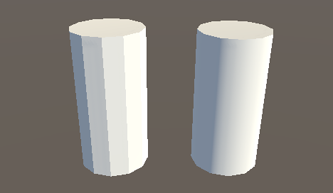
在上面的图中,左边的圆柱体为基本且单调的造影,每个多边形根据相对光源的角度而着色阴影。每个多边形上,贯穿整个多边形区域的光照是不变的,因为表面是单调的。这里有两个相同的圆柱体,它们的线框图可见:
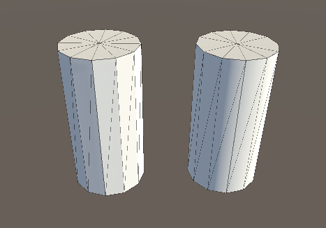
右边的模型有着与左边模型相同的多边形数量,然而着色显得平滑——通过了多边形的光照形成了弧形表面的观感。这是为什么呢?原因是:在每个点用于反射光的表面法线,沿多边形宽的方向梯度地变动;所以对于表面上任何给定的点,光的反射让表面像是弧形,而非它事实上单调不变的多边形。
看成一个二维图形,围绕圆柱体的其中三个单调投影表面多边形,看起来会像是这样:
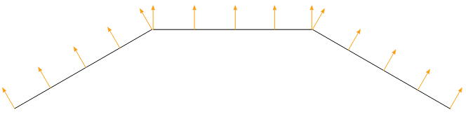
在三个多边形上的单调投影,二维方式观看
表面的法线用橙色的箭头表示。会有数值被用来计算光线如何在表面上反射,因此可以看到,光照在每个多边形的长度上产生相同的反射,因为表面法线指向相同的方向。这导致了“单调的投影”,并且是左边圆柱体的多边形显得有生硬边缘的原因。
然而对于平滑投影的圆柱体,表面法线在平面多边形上变化,如以下所示:
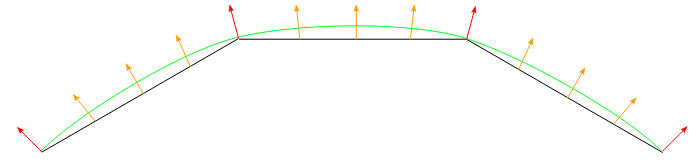
在三个平面上的平滑投影,二维方式观看
法线方向在平面多边形表面上逐步变化,因此表面上的投影产生了平滑弧形的效果(如绿线所示)。这不影响网格实际上的多边形本质,仅仅是光照在平整表面上如何计算。这表面上的弧形表面并非真实,以掠射角观察表面将会揭露表面是平整多边形的本质;然而从大多数观察角度,圆柱体显得拥有平滑的弧形表面。
使用这个基本的平滑造影,决定法线方向的数据实际上仅存储每个向量,这样表面上值的改变,是在一个向量与下一个之间进行插值。在上面的观察中,红色箭头指明在每个向量存储的法线方向,橙色箭头象征在多边形的区域中插值法线方向的例子。
什么是法线贴图?
法线贴图让这个对表面法线的修改进一步深入,通过使用一个纹理来储存关于如何修改模型所有表面法线的信息。一个法线贴图是一个映射到模型表面的图片纹理,类似于颜色纹理;然而法线贴图纹理(称为一个texel)中的每个像素表示:一个在表面法线方向,相对“真实”平整(或平滑插值)表面法线的偏离。
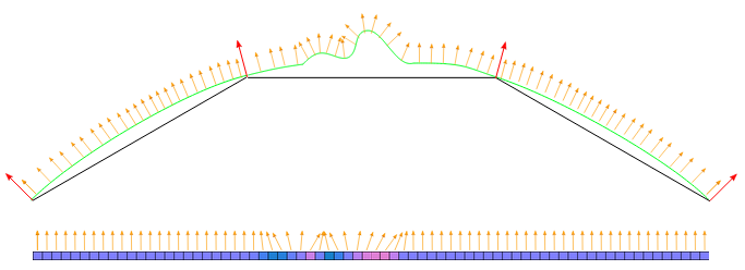
这里,再次是一个三维模型表面上的三个多边形的二维表示,每个橙色箭头对应法线贴图纹理上的一个像素。下方是一个法线贴图纹理的单像素切片图。在中间,可以看到法线已经被修改,造成了多边形表面上一些凹凸的外观。这些凹凸仅会因光线照射在表面而明显,因为这些改动的法线被用于光照计算。
The colours visible in a raw normal map file typically have a blueish hue, and don’t contain any actual light or dark shading - this is because the colours themselves are not intended to be displayed as they are. Instead, the RGB values of each texel represent the X,Y & Z values of a direction vector, and are applied as a modification to the basic interpolated smooth normals of the polygon surfaces.
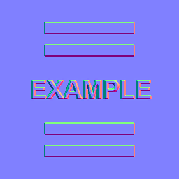
This is a simple normal map, containing the bump information for some raised rectangles and text. This normal map can be imported into Unity and placed into Normal Map slot of the Standard Shader. When combined in a material with a colour map (the Albedo map) and applied to the surface of of the cylinder mesh above, the result looks like this:
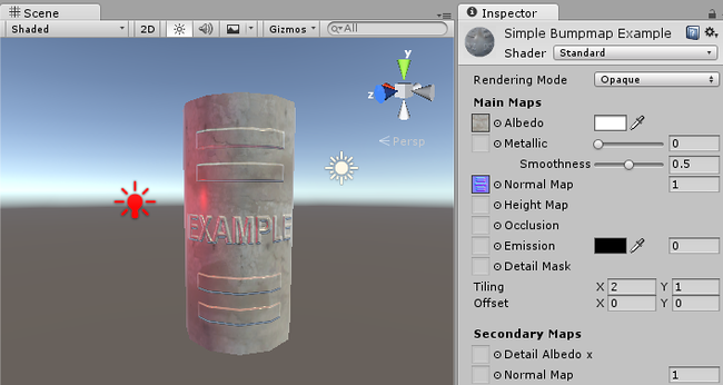
Again, this does not affect the actual polygonal nature of the mesh, only how the lighting is calculated on the surfaces. This apparent raised lettering and shapes on the surface are not really present, and viewing the faces at glancing angles will reveal the true nature of the flat surface, however from most viewing angles the cylinder now appears to have embossed detail raised off the surface.
How do I get or make normal maps?
Commonly, Normal Maps are produced by 3D or Texture artists in conjunction with the model or textures they are producing, and they often mirror the layout and contents of the Albedo map. Sometimes they are produced by hand, and sometimes they are rendered out from a 3D application.
How to render normal maps from a 3D application is beyond the scope of this documentation, however the basic concept is that a 3D artist would produce two versions of a model - a very high resolution model containing all detail as polygons, and a lower-res “game ready” model. The high res model would be too detailed to run optimally in a game (too many triangles in the mesh), but it is used in the 3D modelling application to generate the normal maps. The lower-res version of model can then omit the very fine level of geometry detail that is now stored in the normal maps, so that it can be rendered using the normal mapping instead. A typical use case for this would be to show the bumped detail of creases, buttons, buckles and seams on a characters clothing.
There are some software packages which can analyse the lighting in a regular photographic texture, and extract a normalmap from it. This works by assuming the original texture is lit from a constant direction, and the light and dark areas are analysed and assumed to correspond with angled surfaces. However, when actually using a bump map, you need to make sure that your Albedo texture does not have lighting from any particular direction in the image - ideally it should represent the colours of the surface with no lighting at all - because the lighting information will be calculated by Unity according to the light direction, surface angle and bump map information.
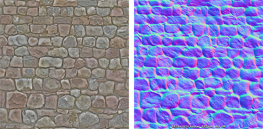
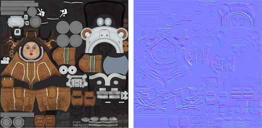
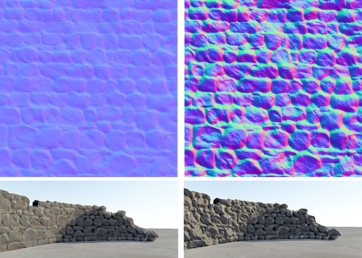
Here are two examples, one is a simple repeating stone wall texture with its corresponding normal map, and one is a character’s texture atlas with its corresponding normal map:
What’s the difference between Bump Maps, Normal Maps and Height Maps?
Normal Maps and Height Maps are both types of Bump Map. They both contain data for representing apparent detail on the surface of simpler polygonal meshes, but they each store that data in a different way.
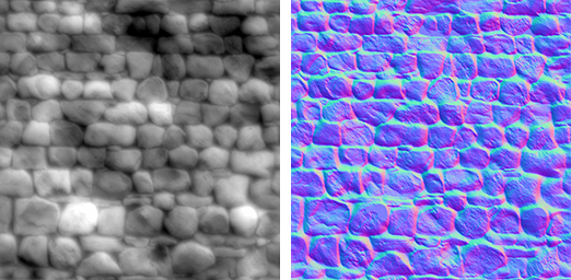
Above, on the left, you can see a height map used for bump mapping a stone wall. A height map is a simple black and white texture, where each pixel represents the amount that point on the surface should appear to be raised. The whiter the pixel colour, the higher the area appears to be raised.
A normal map is an RGB texture, where each pixel represents the difference in direction the surface should appear to be facing, relative to its un-modified surface normal. These textures tend to have a bluey-purple tinge, because of the way the vector is stored in the RGB values.
Modern realtime 3D graphics hardware rely on Normal Maps, because they contain the vectors required to modify how light should appear to bounce of the surface. Unity can also accept Height Maps for bump mapping, but they must be converted to Normal Maps on import in order to use them.
Why the bluey-purple colours?
Understanding this is not vital for using normal maps! It’s ok to skip this paragraph. However if you really want to know: The RGB colour values are used to store the X,Y,Z direction of the vector, with Z being “up” (contrary to Unity’s usual convention of using Y as “up”). In addition, the values in the texture are treated as having been halved, with 0.5 added. This allows vectors of all directions to be stored. Therefore to convert an RGB colour to a vector direction, you must multiply by two, then subtract 1. For example, an RGB value of (0.5, 0.5, 1) or #8080FF in hex results in a vector of (0,0,1) which is “up” for the purposes of normal-mapping - and represents no change to the surface of the model. This is the colour you see in the flat areas of the “example” normal map earlier on this page.

A value of (0.43, 0.91, 0.80) gives a vector of (–0.14, 0.82, 0.6), which is quite a steep modification to the surface. Colours like this can be seen in the bright cyan areas of the stone wall normal map at the top of some of the stone edges. The result is that these edges catch the light at a very different angle to the flatter faces of the stones.

Normal maps
How to import and use Normal Maps and Height Maps
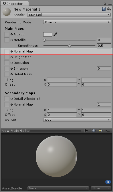
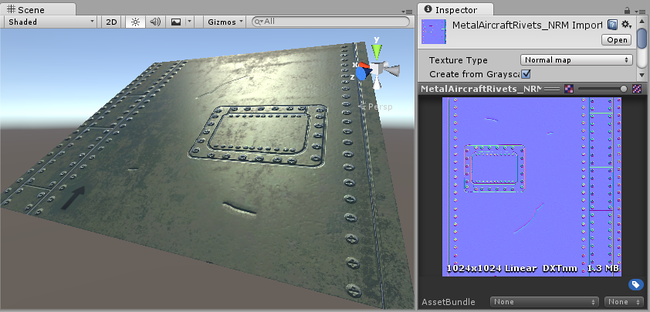
A normal map can be imported by placing the texture file in your assets folder, as usual. However, you need to tell Unity that this texture is a normal map. You can do this by changing the “Texture Type” setting to “Normal Map” in the import inspector settings.
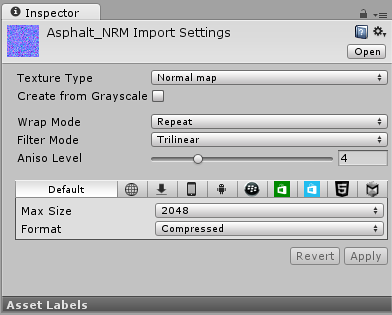
To import a black and white heightmap as a normal map, the process is almost identical, except you need to check the “Create from Greyscale” option.
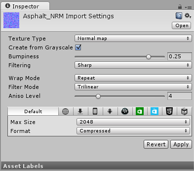
With “Create From Greyscale” selected, a Bumpiness slider will appear in the inspector. You can use this to control how steep the angles in the normalmap are, when being converted from the heights in your heightmap. A low bumpiness value will mean that even sharp contrast in the heightmap will be translated to gentle angles and bumps. A high value will create exaggerated bumps and very high contrast lighting responses to the bumps.
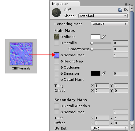
Once you have a normalmap in your assets, you can place it into the Normal Map slot of your Material in the inspector. The Standard Shader has a normal map slot, and many of the older legacy shaders also support normal maps.
If you imported a normalmap or heightmap, and did not mark it as a normal map (By selecting Texture Type: Normal Map as described above), the Material inspector will warn you about this and offer to fix it, as so:
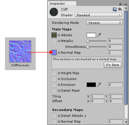
Clicking “Fix Now” has the same effect as selecting Texture Type: Normal Map in the texture inspector settings. This will work if your texture really is a normal map. However if it is a greyscale heightmap, it will not automatically detect this - so for heightmaps you must always select the “Create from Greyscale” option in the texture’s inspector window.
Secondary Normal Maps
You may also notice that there is a second Normal Map slot further down in the Material inspector for the Standard Shader. This allows you to use an additional normal map for creating extra detail. You can add a normal map into this slot in the same way as the regular normal map slot, but the intention here is that you should use a different scale or frequency of tiling so that the two normal maps together produce a high level of detail at different scales. For example, your regular normal map could define the details of panelling on a wall or vehicle, with groves for the panel edges. A secondary normal map could provide very fine bump detail for scratches and wear on the surface which may be tiled at 5 to 10 times the scale of the base normal map. These details could be so fine as to only be visible when examined closely. To have this amount of detail on the base normal map would require the base normal map to be incredibly large, however by combining two at different scales, a high overall level of detail can be achieved with two relatively small normal map textures.