目录
1 LiDAR_front_end.cpp简介
激光点云首先在LiDAR_front_end节点中提取特征点,将处理完的信息通过/laser_cloud_flat完成节点的发送出去,与FAST-LIO2相同R3LIVE也只用到了面特征作为ESIKF融合。
- 首先主函数会根据不同的雷达类型运行不同的回调函数
- 接着通过give_feature()提取角点和面点
- 提取面点时,通过plane_judge()面点类型的判断
- 提取过程中,会进行边缘点判断,也就是LOAM论文中的进行异常点剔除
- 最后将提取的角点和面点发布出去
2 LiDAR_front_end.cpp程序解析
这部分内容和FAST-LIO2的内容类似,首先在最上面先定义了一系列enum的信息,通过enum选择不同的激光雷达类型,特征点特征等,并通过orgtype存放一些激光雷达点的一些其他属性。
// 枚举类型:表示支持的雷达类型
enum LID_TYPE
{
    AVIA = 1,
    VELO16,
    OUST64
}; //{1, 2, 3}

// 枚举类型:表示特征点的类型
enum Feature
{
    Nor,        // 正常点
    Poss_Plane, // 可能的平面点
    Real_Plane, // 确定的平面点
    Edge_Jump,  // 有跨越的边
    Edge_Plane, // 边上的平面点
    Wire,       // 线段 这个也许当了无效点?也就是空间中的小线段?
    ZeroPoint   // 无效点 程序中未使用
};
// 枚举类型:位置标识
enum Surround
{
    Prev, // 前一个
    Next  // 后一个
};

// 枚举类型:表示有跨越边的类型
enum E_jump
{
    Nr_nor,  // 正常
    Nr_zero, // 0
    Nr_180,  // 180
    Nr_inf,  // 无穷大 跳变较远?
    Nr_blind // 在盲区?
};
// orgtype类:用于存储激光雷达点的一些其他属性
struct orgtype
{
    double range; // 点云在xy平面离雷达中心的距离
    double dista; // 当前点与后一个点之间的距离
    //假设雷达原点为O 前一个点为M 当前点为A 后一个点为N
    double angle[2];  // 这个是角OAM和角OAN的cos值
    double intersect; // 这个是角MAN的cos值
    E_jump edj[2];    // 前后两点的类型
    Feature ftype;    // 点类型

    // 构造函数
    orgtype()
    {
        range = 0;
        edj[Prev] = Nr_nor;
        edj[Next] = Nr_nor;
        ftype = Nor; //默认为正常点
        intersect = 2;
    }
};
接着看文件的主函数:
- 首先会初始化ros节点,然后获取配置文件的参数
- 为了简便,设置一些会用到的全局变量
- 后面根据lidar_type的值进行lidar数据的订阅设置
int main( int argc, char **argv )
{
    /**
     * (1)初始化名为"feature_extract"的ros节点
     */
    ros::init( argc, argv, "feature_extract" );
    ros::NodeHandle n;

    /**
     * (2)从参数服务器上获取参数,如果获取失败则=默认值
     * @note NodeHandle::param(const std::string& param_name, T& param_val, const T& default_val)
     */
    n.param< int >( "Lidar_front_end/lidar_type", lidar_type, 0 );
    n.param< double >( "Lidar_front_end/blind", blind, 0.1 );
    n.param< double >( "Lidar_front_end/inf_bound", inf_bound, 4 );
    n.param< int >( "Lidar_front_end/N_SCANS", N_SCANS, 1 );
    n.param< int >( "Lidar_front_end/group_size", group_size, 8 );
    n.param< double >( "Lidar_front_end/disA", disA, 0.01 );
    n.param< double >( "Lidar_front_end/disB", disB, 0.1 );
    n.param< double >( "Lidar_front_end/p2l_ratio", p2l_ratio, 225 );
    n.param< double >( "Lidar_front_end/limit_maxmid", limit_maxmid, 6.25 );
    n.param< double >( "Lidar_front_end/limit_midmin", limit_midmin, 6.25 );
    n.param< double >( "Lidar_front_end/limit_maxmin", limit_maxmin, 3.24 );
    n.param< double >( "Lidar_front_end/jump_up_limit", jump_up_limit, 170.0 );
    n.param< double >( "Lidar_front_end/jump_down_limit", jump_down_limit, 8.0 );
    n.param< double >( "Lidar_front_end/cos160", cos160, 160.0 );
    n.param< double >( "Lidar_front_end/edgea", edgea, 2 );
    n.param< double >( "Lidar_front_end/edgeb", edgeb, 0.1 );
    n.param< double >( "Lidar_front_end/smallp_intersect", smallp_intersect, 172.5 );
    n.param< double >( "Lidar_front_end/smallp_ratio", smallp_ratio, 1.2 );
    n.param< int >( "Lidar_front_end/point_filter_num", point_filter_num, 1 );
    n.param< int >( "Lidar_front_end/point_step", g_LiDAR_sampling_point_step, 3 );
    n.param< int >( "Lidar_front_end/using_raw_point", g_if_using_raw_point, 1 );

    // 设置需要用到的全局变量 - cos(角度->弧度)
    jump_up_limit = cos( jump_up_limit / 180 * M_PI );      // cos(170度)
    jump_down_limit = cos( jump_down_limit / 180 * M_PI );  // cos(8度)
    cos160 = cos( cos160 / 180 * M_PI );                    // cos(160度)
    smallp_intersect = cos( smallp_intersect / 180 * M_PI );// cos(172.5度)

    ros::Subscriber sub_points;

    /**
     * (3)根据lidar_type的值进行lidar数据的订阅设置
     *      绑定订阅后的回调函数
     */
    switch ( lidar_type )
    {
    case MID:   // enum MID = 0 : 默认
        printf( "MID40\n" );
        // 订阅/livox/lidar原始数据,回调函数中转换数据(/laser_cloud),并提取角/面特征后发布出去(laser_cloud_sharp/laser_cloud_flat)
        sub_points = n.subscribe( "/livox/lidar", 1000, mid_handler, ros::TransportHints().tcpNoDelay() );
        break;

    case HORIZON:   // enum HORIZON = 1 : r3live_bag_ouster.launch中设置
        printf( "HORIZON\n" );
        sub_points = n.subscribe( "/livox/lidar", 1000, horizon_handler, ros::TransportHints().tcpNoDelay() );
        break;

    case VELO16:
        printf( "VELO16\n" );   // enum VELO16 = 2 : TODO
        sub_points = n.subscribe( "/velodyne_points", 1000, velo16_handler, ros::TransportHints().tcpNoDelay() );
        break;

    case OUST64:
        printf( "OUST64\n" );   // enum OUST64 = 3 : TODO
        sub_points = n.subscribe( "/os_cloud_node/points", 1000, oust64_handler, ros::TransportHints().tcpNoDelay() );
        break;

    default:
        printf( "Lidar type is wrong.\n" );
        exit( 0 );
        break;
    }

    /**
     * (4)设置需要发布的消息格式
     *      回调函数接收到原始点云后,将其转换为指定格式,并提取角点特征和面特征
     *      然后通过pub_full,pub_surf,pub_corn将消息发布出去
     */
    pub_full = n.advertise< sensor_msgs::PointCloud2 >( "/laser_cloud", 100 );  //发布转换后的消息
    pub_surf = n.advertise< sensor_msgs::PointCloud2 >( "/laser_cloud_flat", 100 ); //发布面特征消息
    pub_corn = n.advertise< sensor_msgs::PointCloud2 >( "/laser_cloud_sharp", 100 );//发布角点特征消息

    ros::spin();
    return 0;
}
文章以livox雷达为例,进入到mid_handler回调函数。mid_handler回调函数接收/livox/lidar原始数据,回调函数中转换数据类型(/laser_cloud),并提取角/面特征后发布出去(laser_cloud_sharp/laser_cloud_flat)
- 首先会进行消息类型的格式转换,通过PointCloud2格式的msg转换为PointXYZINormal格式。
- 接着遍历每一个点云,将点云保存为自定义的vector< orgtype >格式,并设置最后一个点的range信息。
- 接着提取角点和面点
- 最后将提取的角点和面点发布出去
/**
 * @note LiDAR_front_end的回调函数
 *      接收/livox/lidar原始数据,回调函数中转换数据(/laser_cloud),
 *      并提取角/面特征后发布出去(laser_cloud_sharp/laser_cloud_flat)
 */
double vx, vy, vz;
void   mid_handler( const sensor_msgs::PointCloud2::ConstPtr &msg )
{
    // typedef pcl::PointXYZINormal PointType;
    pcl::PointCloud< PointType > pl;    // 存放Lidar点的一维数组
    pcl::fromROSMsg( *msg, pl ); // 通过PointCloud2格式的msg初始化PointXYZINormal的pl

    pcl::PointCloud< PointType > pl_corn, pl_surf;  // 保存提取的角点和平面点
    vector< orgtype >            types; // 自定义的结构提 : TODO
    uint                         plsize = pl.size() - 1;    // Lidar点数量
    pl_corn.reserve( plsize );  // 预留size
    pl_surf.reserve( plsize );  // 预留size
    types.resize( plsize + 1 );

    // 遍历msg中的前n-1个点,按照保存在types中(关键内容:range和dista)
    for ( uint i = 0; i < plsize; i++ )
    {
        types[ i ].range = pl[ i ].x;   //
        vx = pl[ i ].x - pl[ i + 1 ].x; // 相邻两点做差
        vy = pl[ i ].y - pl[ i + 1 ].y; // 得到两点构成
        vz = pl[ i ].z - pl[ i + 1 ].z; // 的向量
        types[ i ].dista = vx * vx + vy * vy + vz * vz;// 向量模长(少开根号)
    }
    // 设置最后一个点的range信息 : =最后一点到原点的距离
    types[ plsize ].range = sqrt( pl[ plsize ].x * pl[ plsize ].x + pl[ plsize ].y * pl[ plsize ].y );

    // 提取角点特征(pl_corn)和面特征(pl_surf)
    give_feature( pl, types, pl_corn, pl_surf );

    // 将转换后的pl,提取到的pl_surf,pl_corn发布出去.
    ros::Time ct( ros::Time::now() );
    pub_func( pl, pub_full, msg->header.stamp );
    pub_func( pl_surf, pub_surf, msg->header.stamp );
    pub_func( pl_corn, pub_corn, msg->header.stamp );
}
give_feature()函数主要是特征提取,下面我们对该函数进行学习和了解,对于每条line的点云提取特征
/**
 * @note 提取Lidar帧的点特征和面特征
 * @param pl : Lidar帧的原始点容器
 * @param types : 对Lidar原始点计算了相邻两点距离后的点容器
 * @param pl_corn : 存放提取到的点特征
 * @param pl_surf : 存放提取到的面特征
 * ***注意*** : 默认没有提取点特征,且只以间隔3个点的形式赋值了面特征
 *             可能是为了速度吧~~~
 */
void give_feature( pcl::PointCloud< PointType > &pl, vector< orgtype > &types,
                   pcl::PointCloud< PointType > &pl_corn,
                   pcl::PointCloud< PointType > &pl_surf )
{
    /*
     * step1:预先判断点数量和点的距离,并定义相关变量
     */
    uint plsize = pl.size();   // 单条线的点数
    uint plsize2;
    if ( plsize == 0 )  // 判断点数量
    {
        printf( "something wrong\n" );
        return;
    }
    uint head = 0;
    while ( types[ head ].range < blind )   // blind = 0.1 : default
    {           // types[i].range = pl[i].x
        head++; // 因此猜测这里判断lidar帧中点的距离
    }           // 保证后续处理的起点在一定距离外,防止干扰点

    // Surf : group_size = 8 : 点数大于8,则后续处理范围为 head -> 点数-8,
    // 否则为0, 因该是只计算head到倒数第8点之间的中间点.
    plsize2 = ( plsize > group_size ) ? ( plsize - group_size ) : 0;

    Eigen::Vector3d curr_direct( Eigen::Vector3d::Zero() ); // 当前平面的法向量
    Eigen::Vector3d last_direct( Eigen::Vector3d::Zero() ); //上一个平面的法向量

    uint i_nex = 0, i2;  // i2为当前点的下一个点
    uint last_i = 0;    // last_i为上一个点的保存的索引
    uint last_i_nex = 0;     // last_i_nex为上一个点的下一个点的索引
    int  last_state = 0;     //为1代表上个状态为平面 否则为0
    int  plane_type;

    PointType ap;// 充当中间交换量的临时容器

    /*
     * step2:对head到倒数第8点之间的中间点进行计算
     */
    for ( uint i = head; i < plsize2; i += g_LiDAR_sampling_point_step )    // g_LiDAR_sampling_point_step = 3
    {
        // 在盲区范围内的点不做处理
        if ( types[ i ].range > blind )
        {
            ap.x = pl[ i ].x;
            ap.y = pl[ i ].y;
            ap.z = pl[ i ].z;
            ap.curvature = pl[ i ].curvature;
            pl_surf.push_back( ap );
        }
        if ( g_if_using_raw_point )
        {
            continue;
        }
        //更新i2
        i2 = i;
        //求得平面,并返回类型0 1 2
        plane_type = plane_judge( pl, types, i, i_nex, curr_direct );
        //返回1:一般默认是平面
        if ( plane_type == 1 )
        {
            for ( uint j = i; j <= i_nex; j++ )
            {
                if ( j != i && j != i_nex )
                {
                    //把起始点和终止点之间的所有点设置为确定的平面点
                    types[ j ].ftype = Real_Plane;
                }
                else
                {
                    //把起始点和终止点设置为可能的平面点
                    types[ j ].ftype = Poss_Plane;
                }
            }

            // 最开始last_state=0直接跳过, 之后last_state=1
            // //如果之前状态是平面则判断当前点是处于两平面边缘的点还是较为平坦的平面的点
            if ( last_state == 1 && last_direct.norm() > 0.1 )
            {
                double mod = last_direct.transpose() * curr_direct;
                if ( mod > -0.707 && mod < 0.707 )
                {
                    //修改ftype,两个面法向量夹角在45度和135度之间 认为是两平面边缘上的点
                    types[ i ].ftype = Edge_Plane;
                }
                else
                {
                    //否则认为是真正的平面点
                    types[ i ].ftype = Real_Plane;
                }
            }

            i = i_nex - 1;
            last_state = 1;
        }
        else if ( plane_type == 2 )
        {
            // plane_type=2的时候
            i = i_nex;
            last_state = 0; // 设置为不是平面点
        }
        else if ( plane_type == 0 )
        {
            // plane_type=2的时候
            // 为1代表上个状态为平面
            if ( last_state == 1 )
            {
                uint i_nex_tem;
                uint j;
                // 遍历区间中的点重新进行判断
                for ( j = last_i + 1; j <= last_i_nex; j++ )
                {
                    uint            i_nex_tem2 = i_nex_tem;
                    Eigen::Vector3d curr_direct2;

                    uint ttem = plane_judge( pl, types, j, i_nex_tem, curr_direct2 );

                    if ( ttem != 1 )
                    {
                        i_nex_tem = i_nex_tem2;
                        break;
                    }
                    curr_direct = curr_direct2;
                }

                if ( j == last_i + 1 )
                {
                    last_state = 0;
                }
                else
                {
                    for ( uint k = last_i_nex; k <= i_nex_tem; k++ )
                    {
                        if ( k != i_nex_tem )
                        {
                            //把起始点和终止点之间的所有点设置为确定的平面点
                            types[ k ].ftype = Real_Plane;
                        }
                        else
                        {
                            //把起始点和终止点设置为可能的平面点
                            types[ k ].ftype = Poss_Plane;
                        }
                    }
                    i = i_nex_tem - 1;
                    i_nex = i_nex_tem;
                    i2 = j - 1;
                    last_state = 1;
                }
            }
        }
        // 更新变量
        last_i = i2;
        last_i_nex = i_nex;
        last_direct = curr_direct;
    }
    if ( g_if_using_raw_point )
    {
        return;
    }

   // 下面进行边缘点的提取
    plsize2 = plsize > 3 ? plsize - 3 : 0; //如果剩下的点数小于3则不判断边缘点,否则计算哪些点是边缘点
    for ( uint i = head + 3; i < plsize2; i++ )
    {
        //点不能在盲区或者点必须属于正常点和可能的平面点,否则退出
        if ( types[ i ].range < blind || types[ i ].ftype >= Real_Plane )
        {
            continue;
        }
        //该点与前后点的距离不能挨的太近
        if ( types[ i - 1 ].dista < 1e-16 || types[ i ].dista < 1e-16 )
        {
            continue;
        }

        Eigen::Vector3d vec_a( pl[ i ].x, pl[ i ].y, pl[ i ].z );   //当前点坐标组成的向量
        Eigen::Vector3d vecs[ 2 ];

        for ( int j = 0; j < 2; j++ )
        {
            int m = -1;
            if ( j == 1 )
            {
                m = 1;
            }
            //若当前的前/后一个点在盲区内(4m)
            if ( types[ i + m ].range < blind )
            {
                if ( types[ i ].range > inf_bound )
                {
                    //若其大于10m
                    //赋予该点Nr_blind(在盲区)
                    types[ i ].edj[ j ] = Nr_inf;
                }
                else
                {
                    //赋予该点Nr_blind(在盲区)
                    types[ i ].edj[ j ] = Nr_blind;
                }
                continue;
            }

            vecs[ j ] = Eigen::Vector3d( pl[ i + m ].x, pl[ i + m ].y, pl[ i + m ].z );
            vecs[ j ] = vecs[ j ] - vec_a; //前、后点指向当前点的向量

            //若雷达坐标系原点为O,当前点为A,前、后一点为M和N
            //则下面OA点乘MA/(|OA|*|MA|),得到的是cos角OAM的大小
            types[ i ].angle[ j ] = vec_a.dot( vecs[ j ] ) / vec_a.norm() / vecs[ j ].norm();
            if ( types[ i ].angle[ j ] < jump_up_limit )
            {
                // M在OA延长线上
                types[ i ].edj[ j ] = Nr_180;
            }
            else if ( types[ i ].angle[ j ] > jump_down_limit )
            {
                // M在OA上
                types[ i ].edj[ j ] = Nr_zero;
            }
        }

        types[ i ].intersect = vecs[ Prev ].dot( vecs[ Next ] ) / vecs[ Prev ].norm() / vecs[ Next ].norm();
        if ( types[ i ].edj[ Prev ] == Nr_nor && types[ i ].edj[ Next ] == Nr_zero && types[ i ].dista > 0.0225 &&
             types[ i ].dista > 4 * types[ i - 1 ].dista )
        {
            //角MAN要小于160度,不然就平行于激光了
            if ( types[ i ].intersect > cos160 )
            {
                if ( edge_jump_judge( pl, types, i, Prev ) )
                {
                    types[ i ].ftype = Edge_Jump;
                }
            }
        }
        // 前一个点在激光束上 && 后一个点正常 && 前一个点与当前点的距离大于0.0225m && 前一个点与当前点的距离大于当前点与后一个点距离的四倍
        else if ( types[ i ].edj[ Prev ] == Nr_zero && types[ i ].edj[ Next ] == Nr_nor && types[ i - 1 ].dista > 0.0225 &&
                  types[ i - 1 ].dista > 4 * types[ i ].dista )
        {
            if ( types[ i ].intersect > cos160 )
            {
                if ( edge_jump_judge( pl, types, i, Next ) )
                {
                    types[ i ].ftype = Edge_Jump;
                }
            }
        }
        // 前面的是正常点 && (当前点到中心距离>10m并且后点在盲区)
        else if ( types[ i ].edj[ Prev ] == Nr_nor && types[ i ].edj[ Next ] == Nr_inf )
        {
            if ( edge_jump_judge( pl, types, i, Prev ) )
            {
                types[ i ].ftype = Edge_Jump;
            }
        }
        // (当前点到中心距离>10m并且前点在盲区) && 后面的是正常点
        else if ( types[ i ].edj[ Prev ] == Nr_inf && types[ i ].edj[ Next ] == Nr_nor )
        {
            if ( edge_jump_judge( pl, types, i, Next ) )
            {
                types[ i ].ftype = Edge_Jump;
            }
        }
        // 前后点都不是正常点
        else if ( types[ i ].edj[ Prev ] > Nr_nor && types[ i ].edj[ Next ] > Nr_nor )
        {
            if ( types[ i ].ftype == Nor )
            {
                types[ i ].ftype = Wire;
            }
        }
    }

    plsize2 = plsize - 1;
    double ratio;
    //继续找平面点
    for ( uint i = head + 1; i < plsize2; i++ )
    {
        //前面、当前、之后三个点都需要不在盲区内
        if ( types[ i ].range < blind || types[ i - 1 ].range < blind || types[ i + 1 ].range < blind )
        {
            continue;
        }
        //前面和当前、当前和之后的点与点之间距离都不能太近
        if ( types[ i - 1 ].dista < 1e-8 || types[ i ].dista < 1e-8 )
        {
            continue;
        }

        //还剩下来一些正常点继续找平面点
        if ( types[ i ].ftype == Nor )
        {
            //求点与点间距的比例,大间距/小间距
            if ( types[ i - 1 ].dista > types[ i ].dista )
            {
                ratio = types[ i - 1 ].dista / types[ i ].dista;
            }
            else
            {
                ratio = types[ i ].dista / types[ i - 1 ].dista;
            }
            //如果夹角大于172.5度 && 间距比例<1.2
            if ( types[ i ].intersect < smallp_intersect && ratio < smallp_ratio )
            {
                // 前后三个点认为是平面点
                if ( types[ i - 1 ].ftype == Nor )
                {
                    types[ i - 1 ].ftype = Real_Plane;
                }
                if ( types[ i + 1 ].ftype == Nor )
                {
                    types[ i + 1 ].ftype = Real_Plane;
                }
                types[ i ].ftype = Real_Plane;
            }
        }
    }
    //存储平面点
    int last_surface = -1;
    for ( uint j = head; j < plsize; j++ )
    {
        //可能的平面点和确定的平面点
        if ( types[ j ].ftype == Poss_Plane || types[ j ].ftype == Real_Plane )
        {
            if ( last_surface == -1 )
            {
                last_surface = j;
            }
            //通常连着好几个都是面点
            //必须在采样间隔上的平面点才使用(这里的是无差别滤波 从每次新找到面点开始每几个点才取一个)
            if ( j == uint( last_surface + point_filter_num - 1 ) )
            {
                PointType ap;
                ap.x = pl[ j ].x;
                ap.y = pl[ j ].y;
                ap.z = pl[ j ].z;
                ap.curvature = pl[ j ].curvature;
                pl_surf.push_back( ap );

                last_surface = -1;
            }
        }
        else
        {
            //跳变较大的边缘边的点和位于平面边缘的点
            if ( types[ j ].ftype == Edge_Jump || types[ j ].ftype == Edge_Plane )
            {
                pl_corn.push_back( pl[ j ] );
            }
            //假如上次找到的面点被无差别滤波掉了,而此时已经到了边缘
            if ( last_surface != -1 )
            {
                PointType ap;
                //取上次面点到此次边缘线之间的所有点的重心当作一个面点存储进去
                for ( uint k = last_surface; k < j; k++ )
                {
                    ap.x += pl[ k ].x;
                    ap.y += pl[ k ].y;
                    ap.z += pl[ k ].z;
                    ap.curvature += pl[ k ].curvature;
                }
                ap.x /= ( j - last_surface );
                ap.y /= ( j - last_surface );
                ap.z /= ( j - last_surface );
                ap.curvature /= ( j - last_surface );
                pl_surf.push_back( ap );
            }
            last_surface = -1;
        }
    }
}
通过plane_judge()面点类型的判断,面特征主要是主要是依据点与点之间的距离来拟合成一个向量,并通过乘积来计算出面特征的提取,这里的面特征提取和边缘特征提取和LOAM的类似。
LOAM特征提取方法:LOAM提出了一种简单而高效的特征点提取方式:根据点云点的曲率提取特征点。即把特别尖锐的边线点与特别平坦的平面点作为特征点。公式看起来比较复杂,实际上就是同一条扫描线上的取目标点左右两侧各5个点,分别与目标点的坐标作差,得到的结果就是目标点的曲率。当目标点处在棱或角的位置时,自然与周围点的差值较大,得到的曲率较大;反之当目标点在平面上时,周围点与目标点的坐标相近,得到的曲率自然较小。

/*
* 平面类型判断
*/
int plane_judge( const pcl::PointCloud< PointType > &pl, vector< orgtype > &types, uint i_cur, uint &i_nex, Eigen::Vector3d &curr_direct )
{
// 0.01*sqrt(x^2+y^2)+0.1,基本上可以近似看成是0.1,100m的时候才到0.2
double group_dis = disA * types[ i_cur ].range + disB;
group_dis = group_dis * group_dis;
// i_nex = i_cur;
double two_dis;
vector< double > disarr; // 前后点距离数组
disarr.reserve( 20 );
for ( i_nex = i_cur; i_nex < i_cur + group_size; i_nex++ )
{
if ( types[ i_nex ].range < blind )
{
// 距离雷达原点太小了将法向量设置为零向量
curr_direct.setZero();
return 2;
}
// 存储当前点与后一个点的距离
disarr.push_back( types[ i_nex ].dista );
}
//看看后续的点有没有满足条件的
for ( ;; )
{
//索引超出所有点的个数直接break
if ( ( i_cur >= pl.size() ) || ( i_nex >= pl.size() ) )
break;
if ( types[ i_nex ].range < blind )
{
// 距离雷达原点太小了将法向量设置为零向量
curr_direct.setZero();
return 2;
}
//最后的i_nex点到i_cur点的距离
vx = pl[ i_nex ].x - pl[ i_cur ].x;
vy = pl[ i_nex ].y - pl[ i_cur ].y;
vz = pl[ i_nex ].z - pl[ i_cur ].z;
two_dis = vx * vx + vy * vy + vz * vz;
//距离i_cur点太远了就直接break
if ( two_dis >= group_dis )
{
break;
}
disarr.push_back( types[ i_nex ].dista ); //存储当前点与后一个点的距离
i_nex++;
}
double leng_wid = 0;
double v1[ 3 ], v2[ 3 ];
for ( uint j = i_cur + 1; j < i_nex; j++ )
{
if ( ( j >= pl.size() ) || ( i_cur >= pl.size() ) )
break;
//假设i_cur点为A,j点为B i_nex点为C
//向量AB
v1[ 0 ] = pl[ j ].x - pl[ i_cur ].x;
v1[ 1 ] = pl[ j ].y - pl[ i_cur ].y;
v1[ 2 ] = pl[ j ].z - pl[ i_cur ].z;
//向量AB叉乘向量AC
v2[ 0 ] = v1[ 1 ] * vz - vy * v1[ 2 ];
v2[ 1 ] = v1[ 2 ] * vx - v1[ 0 ] * vz;
v2[ 2 ] = v1[ 0 ] * vy - vx * v1[ 1 ];
//物理意义是组成的ABC组成的平行四边形面积的平方(为|AC|*h,其中为B到线AC的距离)
double lw = v2[ 0 ] * v2[ 0 ] + v2[ 1 ] * v2[ 1 ] + v2[ 2 ] * v2[ 2 ];
if ( lw > leng_wid )
{
//寻找最大面积的平方,也就是寻找距离AC最远的B
leng_wid = lw;
}
}
//|AC|*|AC|/(|AC|*|AC|*h*h)<225
//也就是h>1/15 B点到AC的距离要大于0.06667m
//太近了不好拟合一个平面
if ( ( two_dis * two_dis / leng_wid ) < p2l_ratio )
{
//太近了法向量直接设置为0
curr_direct.setZero();
return 0;
}
//把两点之间的距离,按从大到小排个顺序
uint disarrsize = disarr.size();
for ( uint j = 0; j < disarrsize - 1; j++ )
{
for ( uint k = j + 1; k < disarrsize; k++ )
{
if ( disarr[ j ] < disarr[ k ] )
{
leng_wid = disarr[ j ];
disarr[ j ] = disarr[ k ];
disarr[ k ] = leng_wid;
}
}
}
//如果两点间的距离太近了
if ( disarr[ disarr.size() - 2 ] < 1e-16 )
{
//太近了法向量直接设置为0
curr_direct.setZero();
return 0;
}
if ( lidar_type == MID || lidar_type == HORIZON )
{
//点与点之间距离变化太大的时候,可能与激光束是平行的,就也舍弃了
double dismax_mid = disarr[ 0 ] / disarr[ disarrsize / 2 ];
double dismid_min = disarr[ disarrsize / 2 ] / disarr[ disarrsize - 2 ];
if ( dismax_mid >= limit_maxmid || dismid_min >= limit_midmin )
{
//太近或太远,法向量直接设置为0
curr_direct.setZero();
return 0;
}
}
else
{
double dismax_min = disarr[ 0 ] / disarr[ disarrsize - 2 ];
if ( dismax_min >= limit_maxmin )
{
curr_direct.setZero();
return 0;
}
}
curr_direct << vx, vy, vz;
curr_direct.normalize(); //法向量归一化
return 1;
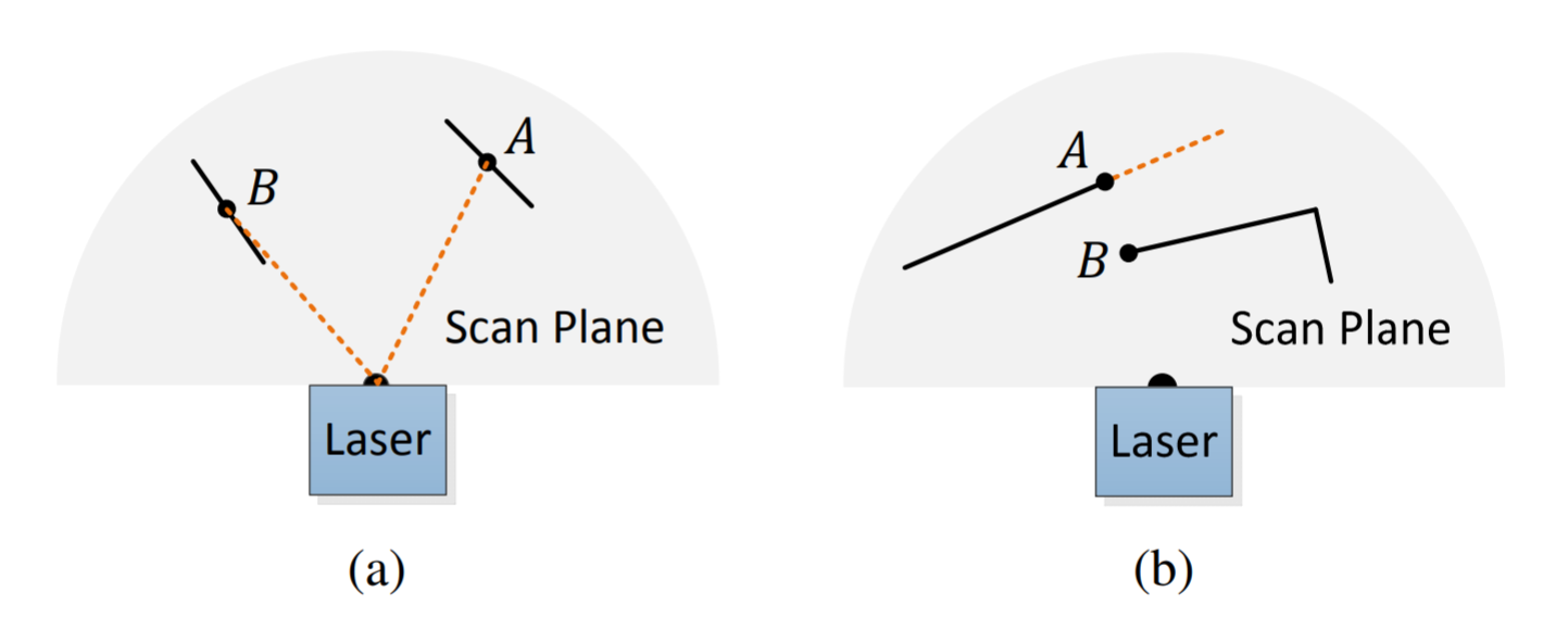
}边界特征主要是为了防止下面的两种情况所加入的判断。在LOAM中也有体现,在A-LOAM代码中没有体现异常点剔除,FAST-LIO2中进行了异常点剔除的判断。
LOAM论文:如图所示(a)实线段代表局部表面块。点A位于与激光束有一定角度的表面上(橙色虚线段)。点B位于与激光束大致平行的表面上。我们认为B是一个不可靠的特征点,不选择它作为特征点。(b)实线段是激光可观测的物体。点A在被遮挡区域的边界上(橙色虚线段),可以检测到边缘点。然而,如果从不同的角度观察,被遮挡的区域可以改变并变得可观察到。我们不把A作为显著边点,也不选择A可靠的特征点。
/*
* 边缘点判断,也就是LOAM论文中的进行异常点剔除
* 条件1:当前点前两个点不能在盲区
* 条件2:当前点后两个点不能在盲区
*/
bool edge_jump_judge( const pcl::PointCloud< PointType > &pl, vector< orgtype > &types, uint i, Surround nor_dir )
{
    if ( nor_dir == 0 )
    {
        //前两个点不能在盲区
        if ( types[ i - 1 ].range < blind || types[ i - 2 ].range < blind )
        {
            return false;
        }
    }
    else if ( nor_dir == 1 )
    {
        //后两个点不能在盲区
        if ( types[ i + 1 ].range < blind || types[ i + 2 ].range < blind )
        {
            return false;
        }
    }

    // 下面分别对(i-2,i-1)和(i,i+1)两种情况时点与点间距进行了判断
    double d1 = types[ i + nor_dir - 1 ].dista;
    double d2 = types[ i + 3 * nor_dir - 2 ].dista;
    double d;

    if ( d1 < d2 )
    {
        //将大小间距进行调换,大在前小在后
        d = d1;
        d1 = d2;
        d2 = d;
    }

    d1 = sqrt( d1 );
    d2 = sqrt( d2 );

    if ( d1 > edgea * d2 || ( d1 - d2 ) > edgeb )
    {
        //假如间距太大 可能是被遮挡,就不把它当作边缘点
        return false;
    }

    return true;
}