考虑到实用性问题,把代码相关的内容放在前面,理论相关的放在后面。但是实际最好的阅读顺序还是按照1、2、3的顺序吧(这也是我写这个博客的顺序)
2. 坐标系方向orientation(RAI → AIL)
2.1 统一转为RAI方向(itk的python代码)
参考知乎文章:NIfTI格式医学图像不同方向之间旋转
import itk
import numpy as np

def reorient_atlas_to_image(image):
    """
    Reorient image to RAI orientation.
    :param image: Input itk image.
    :return: Input image reoriented to RAI.
    """
    filter = itk.OrientImageFilter.New(image)
    filter.UseImageDirectionOn()
    filter.SetInput(image)
    m = itk.GetMatrixFromArray(np.array([[1, 0, 0], [0, 1, 0], [0, 0, 1]], np.float64))
    filter.SetDesiredCoordinateDirection(m)
    filter.Update()
    reoriented = filter.GetOutput()
    return reoriented

atlas_path = "./atlasImage.mha"
PixelType = itk.ctype("float")
atlas = itk.imread(atlas_path,PixelType)
reorient_atlas = reorient_atlas_to_image(atlas)
itk.imwrite(reorient_atlas, "./reorient_atlas.nii.gz")
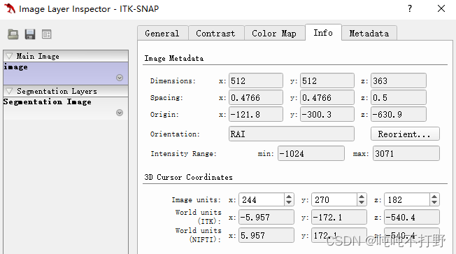
转换前后的图像信息对比:
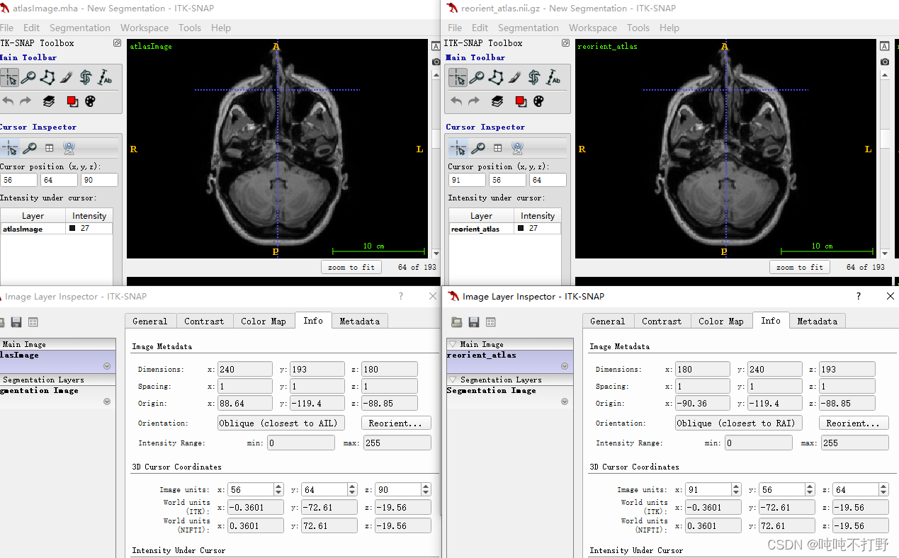
可以看到,三个轴变了,origin也有一点点变化。
2.2. 统一转为某个方向(itk的C++代码)
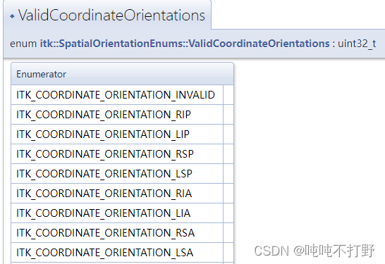
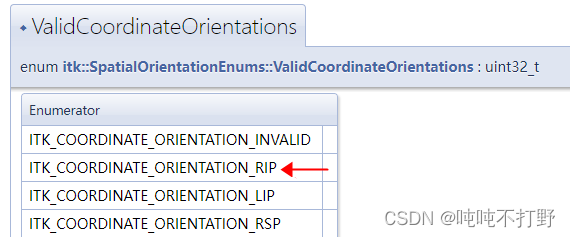
关于可以使用的方向的枚举值,例如:itk::SpatialOrientation::ITK_COORDINATE_ORIENTATION_AIL,可以参考ValidCoordinateOrientations
具体代码实现:
#include <itkOrientImageFilter.h>
#include <itkSpatialOrientation.h>

void testOriention() {


  // read image
  std::string ASL_image_path = "/data/data1/hs/CodeEditTest/ITKMinimalPathExtraction3D/TOF_2D_obl_MRV.nii.gz";
  ShortImagePointer ASL_image = readImage<short>(ASL_image_path);

  // define OrientImageFilter
  typedef itk::Image<short, 3> ImageType;
  itk::OrientImageFilter<ImageType, ImageType>::Pointer orienterASL = itk::OrientImageFilter<ImageType, ImageType>::New();

  orienterASL->UseImageDirectionOn();
  // set to fixed orientation,eg. AIL
  orienterASL->SetDesiredCoordinateOrientation(itk::SpatialOrientation::ITK_COORDINATE_ORIENTATION_AIL);
  orienterASL->SetInput(ASL_image);
  orienterASL->Update();
  ShortImagePointer convertedASLImage = orienterASL->GetOutput();
  saveImage<short>(convertedASLImage, "/data/data1/hs/CodeEditTest/ITKMinimalPathExtraction3D/fixedAILOrientation.nii.gz");
}
结果
- 固定成某个方向的,例如:AIL
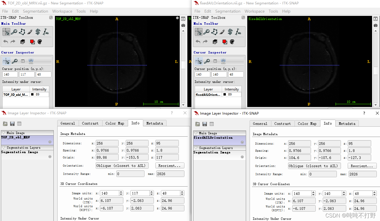
左边是原图,右边是改为AIL方向之后的
2.3 设置成和另一个图方向一样(itk的C++)
2.3.1 方法2
代码
#include <itkOrientImageFilter.h>
#include <itkSpatialOrientation.h>

void testOriention() {


  // read image
  std::string ASL_image_path = "/data/data1/hs/CodeEditTest/ITKMinimalPathExtraction3D/TOF_2D_obl_MRV.nii.gz";
  ShortImagePointer ASL_image = readImage<short>(ASL_image_path);
  std::string RAI_imag_path = "/data/data1/hs/CodeEditTest/ITKMinimalPathExtraction3D/CTA.nii.gz";
  ShortImagePointer RAI_image = readImage<short>(RAI_imag_path);

  // define OrientImageFilter
  typedef itk::Image<short, 3> ImageType;
  itk::OrientImageFilter<ImageType, ImageType>::Pointer orienterASL = itk::OrientImageFilter<ImageType, ImageType>::New();

  // set to another image's orientation

  // get orientation from direction
  ImageType::DirectionType direction = RAI_image->GetDirection();
  std::cout << "will be conveted direction is \n" << direction << "\n";
  typedef itk::SpatialOrientation::ValidCoordinateOrientationFlags CoordinateOrientationCode;
  CoordinateOrientationCode orientation;
  orientation = itk::SpatialOrientationAdapter().FromDirectionCosines(direction);

  orienterASL->UseImageDirectionOn();
  orienterASL->SetDesiredCoordinateOrientation(orientation);
  std::cout << "converted image orientation is: " << orientation << "\n";

  std::cout << "Emum RAI code is: " << itk::SpatialOrientation::ITK_COORDINATE_ORIENTATION_RAI << "\n";
  orienterASL->SetInput(ASL_image);
  orienterASL->Update();
  ShortImagePointer convertedASLImage = orienterASL->GetOutput();
  saveImage<short>(convertedASLImage, "/data/data1/hs/CodeEditTest/ITKMinimalPathExtraction3D/sameAsAnotherImageOrientation.nii.gz");
}
输出结果为:
will be conveted direction is
1 0 0
0 1 0
0 0 1

converted image orientation is: 525570
Emum RAI code is: 525570
转换后的图为:
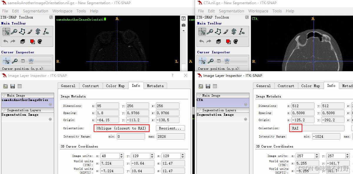
转换正确
说明
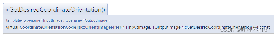
这里注意,不能想当然的认为有SetDesiredCoordinateOrientation,就相应的有GetDesiredCoordinateOrientation(虽然大多数情况下都是这样),还是要仔细看文档说明和函数头文件定义。
- 这里实现借助了itk::SpatialOrientationAdapter Class Reference这个类。
- 这个类的使用参考了[ITK] [ITK-users] SpatialOrientationAdapter
- 其实一开始没看懂这个类是干嘛的,在ITK-Proposals:Orientation这个页面中看到了
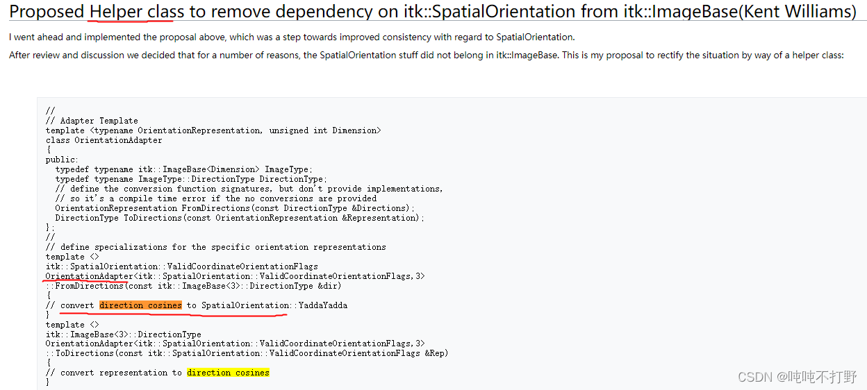
所以知道了itk::SpatialOrientationAdapter这个类是一个辅助类(adapter,接口适配),作用就是转换direction和orientation。
2.3.2 方法1
#include <itkOrientImageFilter.h>
#include <itkSpatialOrientation.h>
void testOriention() {


  // read image
  std::string ASL_image_path = "/data/data1/hs/CodeEditTest/ITKMinimalPathExtraction3D/TOF_2D_obl_MRV.nii.gz";
  ShortImagePointer ASL_image = readImage<short>(ASL_image_path);
  std::string RAI_imag_path = "/data/data1/hs/CodeEditTest/ITKMinimalPathExtraction3D/CTA.nii.gz";
  ShortImagePointer RAI_image = readImage<short>(RAI_imag_path);

  // define OrientImageFilter
  typedef itk::Image<short, 3> ImageType;
  itk::OrientImageFilter<ImageType, ImageType>::Pointer orienterASL = itk::OrientImageFilter<ImageType, ImageType>::New();
  itk::OrientImageFilter<ImageType, ImageType>::Pointer orienterRAI = itk::OrientImageFilter<ImageType, ImageType>::New();

  // set to another image's orientation
  orienterRAI->UseImageDirectionOn();
  orienterRAI->SetInput(RAI_image);
  orienterRAI->Update();

  orienterASL->UseImageDirectionOn();
  orienterASL->SetDesiredCoordinateOrientation(orienterRAI->GetGivenCoordinateOrientation());
  std::cout << "converted image orientation is: " << orienterRAI->GetGivenCoordinateOrientation() << "\n";
  std::cout << "Emum RAI code is: " << itk::SpatialOrientation::ITK_COORDINATE_ORIENTATION_RAI << "\n";
  orienterASL->SetInput(ASL_image);
  orienterASL->Update();
  ShortImagePointer convertedASLImage = orienterASL->GetOutput();
  saveImage<short>(convertedASLImage, "/data/data1/hs/CodeEditTest/ITKMinimalPathExtraction3D/AnotherImageOrientation.nii.gz");
}
输出的结果是:
converted image orientation is: 525570
Emum RAI code is: 525570
2.3.3 错误解决
一开始使用的是
  orienterASL->SetDesiredCoordinateOrientation(orienterRAI->GetDesiredCoordinateOrientation());
  std::cout << "converted image orientation is: " << orienterRAI->GetDesiredCoordinateOrientation() << "\n";
输出是
converted image orientation is: 264194
转换错误,后来改为
orienterASL->SetDesiredCoordinateOrientation(orienterRAI->GetGivenCoordinateOrientation ());
输出就正确了,为:
converted image orientation is: 525570
与设置的RAI的code一样。
上面的情况是:
orienterRAI->GetDesiredCoordinateOrientation()
// 得到的输出是:264194
itk::SpatialOrientation::ITK_COORDINATE_ORIENTATION_RAI
//得到的输出是:525570
itk::SpatialOrientation::ITK_COORDINATE_ORIENTATION_RIP
//得到的输出是:264194
所以GetDesiredCoordinateOrientation这个函数有点问题。。
-
似乎返回的方向是枚举
itk::SpatialOrientationEnums::ValidCoordinateOrientations中的第一个有效值。 -
尝试SetInput()不同方向的图像,
orienterRAI->GetDesiredCoordinateOrientation()输出的都是264194(可能缺少设置了什么???) -
-
另外,这个函数前面有个
virtual关键词,而且在itkOrientImageFilter.h头文件中没有看到这个函数的定义。。。所以可能不是这样使用的
决定使用GetGivenCoordinateOrientation 来替换GetDesiredCoordinateOrientation的原因在于,看到了github上的源代码:
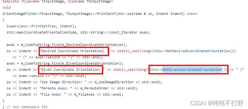
从语言描述上来说,GetGivenCoordinateOrientation 应该是我要的功能。
2.4 方向的枚举值规定
关于方向的枚举值说明,详见:itkSpatialOrientation.h中的定义
查看这些方向enum定义,<<其实就是位运算,可以看看c++ <<和>>的意思
enum class CoordinateTerms : uint8_t
  {


    ITK_COORDINATE_UNKNOWN = 0,
    ITK_COORDINATE_Right = 2,
    ITK_COORDINATE_Left = 3,
    ITK_COORDINATE_Posterior = 4, // back
    ITK_COORDINATE_Anterior = 5,  // front
    ITK_COORDINATE_Inferior = 8,  // below
    ITK_COORDINATE_Superior = 9   // above
                                  // ITK_COORDINATE_Historical=16,
                                  // ITK_COORDINATE_Future=17
  };

  enum class CoordinateMajornessTerms : uint8_t
  {


    ITK_COORDINATE_PrimaryMinor = 0,
    ITK_COORDINATE_SecondaryMinor = 8,
    ITK_COORDINATE_TertiaryMinor = 16
  };

...
 ITK_COORDINATE_ORIENTATION_RAI =
       (static_cast<uint32_t>(CoordinateTerms::ITK_COORDINATE_Right)
        << static_cast<uint32_t>(CoordinateMajornessTerms::ITK_COORDINATE_PrimaryMinor)) +
       (static_cast<uint32_t>(CoordinateTerms::ITK_COORDINATE_Anterior)
        << static_cast<uint32_t>(CoordinateMajornessTerms::ITK_COORDINATE_SecondaryMinor)) +
       (static_cast<uint32_t>(CoordinateTerms::ITK_COORDINATE_Inferior)
        << static_cast<uint32_t>(CoordinateMajornessTerms::ITK_COORDINATE_TertiaryMinor)),
ITK_COORDINATE_ORIENTATION_RIP =
   (static_cast<uint32_t>(CoordinateTerms::ITK_COORDINATE_Right)
    << static_cast<uint32_t>(CoordinateMajornessTerms::ITK_COORDINATE_PrimaryMinor)) +
   (static_cast<uint32_t>(CoordinateTerms::ITK_COORDINATE_Inferior)
    << static_cast<uint32_t>(CoordinateMajornessTerms::ITK_COORDINATE_SecondaryMinor)) +
   (static_cast<uint32_t>(CoordinateTerms::ITK_COORDINATE_Posterior)
    << static_cast<uint32_t>(CoordinateMajornessTerms::ITK_COORDINATE_TertiaryMinor)),
直接按照各自的枚举值,进行位运算,可以得到:
uint32_t RAI = (static_cast<uint32_t>(2) << static_cast<uint32_t>(0)) + (static_cast<uint32_t>(5) << static_cast<uint32_t>(8)) +
               (static_cast<uint32_t>(8) << static_cast<uint32_t>(16));
std::cout << RAI << "\n";
std::cout << itk::SpatialOrientation::ITK_COORDINATE_ORIENTATION_RAI << "\n";

uint32_t RIP = (static_cast<uint32_t>(2) << static_cast<uint32_t>(0)) + (static_cast<uint32_t>(8) << static_cast<uint32_t>(8)) +
               (static_cast<uint32_t>(4) << static_cast<uint32_t>(16));
std::cout << RIP << "\n";
std::cout << itk::SpatialOrientation::ITK_COORDINATE_ORIENTATION_RIP << "\n";
输出为:
525570
525570
264194
264194
参考:
- Github代码:ITK/Modules/Filtering/ImageGrid/include/itkOrientImageFilter.hxx
- ITK讨论:
- 将某个图的坐标系设置成另一个图的坐标系,需要使用set,根据ITK的doxygen:itk::OrientImageFilter< TInputImage, TOutputImage > Class Template Reference,
GetDesiredCoordinateOrientation
这个网页文档中本身就包含例子,在Detailed Description后面 - ITK学习笔记(七) ITK旋转方向位置不变
- 相关的类其实还有一个:itk::SpatialOrientationAdapter Class Reference
3. 世界坐标系和图像坐标系转换(physical space ↔ voxel space)
参考内容:
- 网页版本:4.1.4 Defining Origin and Spacing
- 网页pdf书:ItkSoftwareGuide.pdf,P71-4.1.4 Defining Origin and Spacing部分。
3.1 直接调用ITK现有的函数
3.1.1 代码
void coordinateConvert() {
std::string ASL_image_path = "/data/data1/hs/CodeEditTest/ITKMinimalPathExtraction3D/TOF_2D_obl_MRV.nii.gz";
ShortImagePointer ASL_image = readImage<short>(ASL_image_path);
typedef itk::Image<short, 3> ImageType;
using PointType = itk::Point<double, ImageType::ImageDimension>;
PointType point;
point[0] = 82.7614; // x coordinate
point[1] = -151.254; // y coordinate
point[2] = 114.037; // z coordinate
ImageType::IndexType pixelIndex;
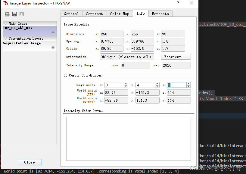
// 世界坐标转voxel坐标
bool isInside = ASL_image->TransformPhysicalPointToIndex(point, pixelIndex);
if (isInside) {
std::cout << "World point is " << point << " ,corresponding is Voxel Index " << pixelIndex << "\n"; }
PointType point2;
// voxel坐标转世界坐标
ASL_image->TransformIndexToPhysicalPoint(pixelIndex, point2);
std::cout << "Voxel Index is " << pixelIndex << " ,corresponding is 2orld point " << point2 << "\n";
}
输出内容:
World point is [82.7614, -151.254, 114.037] ,corresponding is Voxel Index [2, 3, 4]
Voxel Index is [2, 3, 4] ,corresponding is 2orld point [82.7614, -151.254, 114.037]
结果说明
3.1.2 说明
这里其实会发现,根据函数的头文件定义,上面所使用的两个转换函数:
bool 	TransformPhysicalPointToIndex (const Point< TCoordRep, VImageDimension > &point, IndexType &index) const
// 返回是bool值

void 	TransformIndexToPhysicalPoint (const IndexType &index, Point< TCoordRep, VImageDimension > &point) const
// 这个没有返回值
根据itk文档:TransformPhysicalPointToIndex()
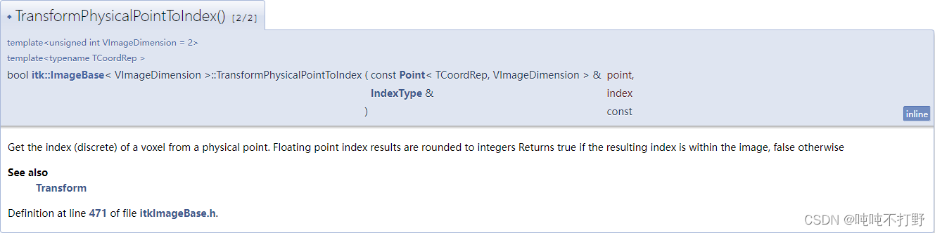
- 这个函数会把计算出的index进行round(四舍五入),
- 如果计算出的的index位于图像范围,则返回
true,否则false。
同时参考:TransformPhysicalPointToIndex that remains inside the boundaries of the image
- 物理坐标转index时,计算可能会导致index出现负值或者图像index之外的情况,因此需要进行bool判断
- 而index转物理坐标的时候,好像不会考虑这个问题,因为一般给index都是从图像里给的,如果人工专门指定一个错误的,那也没办法?
3.2 从头实现的代码
可以根据转换公式,自己手动实现一下。参考slicer软件中RAS转换为像素坐标方法
3.2.1 代码
voxel(itk::Index)和world(itk::Point)互相转换
void worldAndVoxelConvert() {
std::string ASL_image_path = "/data/data1/hs/CodeEditTest/ITKMinimalPathExtraction3D/TOF_2D_obl_MRV.nii.gz";
ShortImagePointer ASL_image = readImage<short>(ASL_image_path);
// get spacing
using MatrixType = itk::Matrix<double, 3, 3>;
MatrixType SpacingMatrix;
SpacingMatrix.Fill(0.0F);
typedef itk::Image<short, 3> ImageType;
const ImageType::SpacingType& ImageSpacing = ASL_image->GetSpacing();
SpacingMatrix(0, 0) = ImageSpacing[0];
SpacingMatrix(1, 1) = ImageSpacing[1];
SpacingMatrix(2, 2) = ImageSpacing[2];
// get direction
const ImageType::DirectionType& ImageDirectionCosines = ASL_image->GetDirection();
// get origin
const ImageType::PointType& ImageOrigin = ASL_image->GetOrigin();
// convert voxel index to world point
const ImageType::IndexType voxelIndex({
2, 3, 4});
using VectorType = itk::Vector<double, Dimension>;
VectorType indexVector;
indexVector[0] = voxelIndex[0];
indexVector[1] = voxelIndex[1];
indexVector[2] = voxelIndex[2];
ImageType::PointType pointWorld = ImageOrigin + ImageDirectionCosines * SpacingMatrix * indexVector;
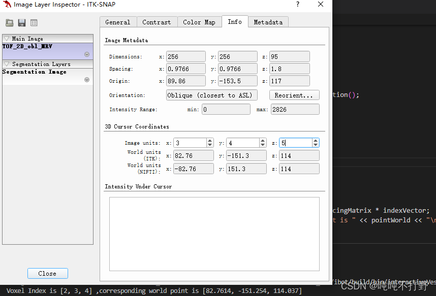
std::cout << "Voxel Index is " << voxelIndex << " , corresponding world point is " << pointWorld << "\n";
// convert world point to voxel index 暂时有点问题
using VectorType = itk::Vector<double, Dimension>;
MatrixType Minv(ImageDirectionCosines.GetInverse());
VectorType spacingVector;
spacingVector[0] = 1 / ImageSpacing[0];
spacingVector[1] = 1 / ImageSpacing[1];
spacingVector[2] = 1 / ImageSpacing[2];
VectorType indexVector2 = Minv * (pointWorld - ImageOrigin) * spacingVector;
ImageType::IndexType voxelIndex2;
voxelIndex2[0] = indexVector2[0];
voxelIndex2[1] = indexVector2[1];
voxelIndex2[2] = indexVector2[2];
std::cout << "world point is " << pointWorld << " , corresponding is Voxel Index" << voxelIndex2 << "\n";
}
输出:
Voxel Index is [2, 3, 4] , corresponding world point is [82.7614, -151.254, 114.037]
world point is [82.7614, -151.254, 114.037] , corresponding  is Voxel Index[8, 8, 8]
世界坐标转voxel还有点问题
对于index为(2,3,4)的点来说,
- 由于itk-snap是从1开始计数,因此需要去查看index为(3,4,5)的点。
- 可以看到输出的计算出的世界系坐标和itk-snap中显示的是基本一致的
3.2.2 说明

3.2 相关理论
主要参考ITK的 https://itk.org/ItkSoftwareGuide.pdf:
- p71页附近,其实写的和 1. 理论性内容中1.4 坐标系转换中差不多
3.2.1 图像转世界
- p74页附近
3.2.2 世界转图像
1. 理论性内容
这部分内容参考:
- 在面对医学影像及相关的应用时,需要解决不同坐标系之间差异的问题。
- 在医学影像成像的使用中,有三种常见的坐标系,彼此之间有非常明显的区别,即:世界坐标系(World coordinate system),解剖(Anatomical)坐标系和图像(Image )坐标系
下图说明了这三种坐标系统及其对应的轴
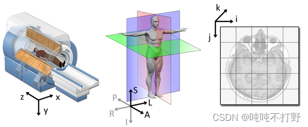
每种坐标系都有各自的意义,以不同的方式描述物体位置信息。
- 解剖坐标系的图像是来自于My MS organization的共享图像。
- Chand John有一个关于Slicer中如何处理坐标系的详细的PPT,这里,60多页,讲的很详细,后续会把ppt中的内容也整理出来
1.1 世界坐标系(World coordinate system)
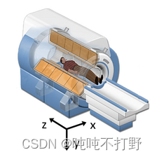
- 世界坐标系通常会采用笛卡尔坐标系( x , y , z x,y,z x,y,z),一般是要被建模的对象所在位置的坐标系(比如:一个MRI的扫描对象或者病人)。
- 每个被建模的对象都有自己的坐标系,但是只有1个世界坐标系来定义每个被建模对象的位置和朝向。
1.2 解剖坐标系(Anatomical coordinate system)
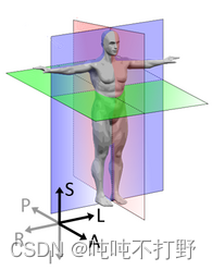
解剖坐标系是医学影像技术中最重要的建模坐标系(也被称为患者坐标系),这个坐标系(空间)由三个平面组成,来描述人体的标准解剖位置
- axial (轴向/横截面)平行于地面,把头部(
Superior)和脚部(Inferior)分开 - coronal(冠状面)垂直于地面,把胸前(
Anterior,前)和背后分开 (Posterior,后) - sagittal(矢状面) 将左边(
Left)和右边(Right)分开
在这些面中,每个轴的刻度都有个正方向(比如:轴向面Axial中,SI这个方向上的负方向就由Inferior 轴表示),上面的6个方向会作为坐标系的正负轴,因此需要确定其中三组轴的正方向。
解剖坐标系是一个连续的三维空间,可以在解剖坐标系中对影像进行采样
- 在神经影像中,一般会相对于要被扫描的人脑来定义这个空间。
- 因此,3D的基(方向向量)是根据解剖轴的前后(anterior-posterior),上下(inferior-superior)和左右(left-right)来定义的。
- 注释: 3D的基(basis),指的其实就类似于线性代数中的基(基底向量,一般是单位向量,可以用来表示平面中任意其它向量)
不过,不同的医学应用使用不同的3D基定义的,最常见的是以下几组基:
- LPS (Left, Posterior, Superior) ,这组基一般用于DICOM图像和ITK套件(itk、itk-snap和simpleitk等)中
L P S = { f r o m r i g h t t o w a r d s l e f t ( 从右到左 ) f r o m a n t e r i o r t o w a r d s p o s t e r i o r ( 从前到后 ) f r o m i n f e r i o r t o w a r d s s u p e r i o r ( 从上到下 ) } LPS= \begin{Bmatrix} from\ \textcolor{red}{r}ight\ towards\ \textcolor{blue}{l} eft(从右到左)\\ from\ \textcolor{red}{a}nterior\ towards\ \textcolor{blue}{p}osterior(从前到后)\\ from\ \textcolor{red}{i}nferior\ towards\ \textcolor{blue}superior(从上到下)\\ \end{Bmatrix} LPS=⎩ ⎨ ⎧from right towards left(从右到左)from anterior towards posterior(从前到后)from inferior towards superior(从上到下)⎭ ⎬ ⎫
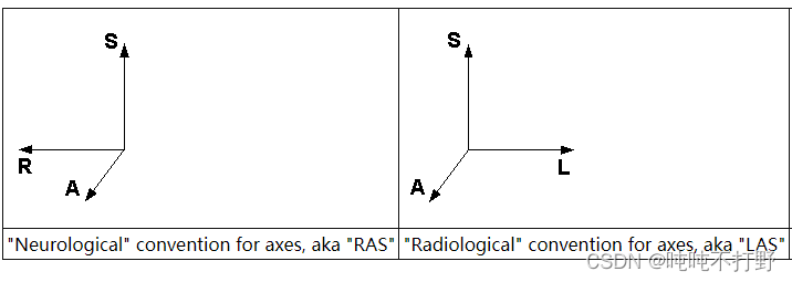
- RAS (Right, Anterior, Superior) 和LPS很像,但是前两个轴翻转了,一般用在3D Slicer中
R A S = { f r o m l e f t t o w a r d s r i g h t ( 从左到右 ) f r o m p o s t e r i o r t o w a r d s a n t e r i o r ( 从后到前 ) f r o m i n f e r i o r t o w a r d s s u p e r i o r ( 从上到下 ) } RAS= \begin{Bmatrix} from\ \textcolor{red}{l}eft\ towards\ \textcolor{blue}{r}ight (从左到右)\\ from\ \textcolor{red}{p}osterior\ towards\ \textcolor{blue}{a}nterior(从后到前)\\ from\ \textcolor{red}{i}nferior\ towards\ \textcolor{blue}{s}uperior(从上到下)\\ \end{Bmatrix} RAS=⎩ ⎨ ⎧from left towards right(从左到右)from posterior towards anterior(从后到前)from inferior towards superior(从上到下)⎭ ⎬ ⎫
这两个基底向量(基)都符合人的逻辑,同时都很重要,知道每个图像的基是必要的。
- 同时上面两种坐标系都是右手坐标系,实际还有可能会遇到左手坐标系,
- 关于左手和右手坐标系,可以查看1.7 左手坐标系和右手坐标系的内容
注意
- LPS和RAS都是使用到达的方向来表示的,
- 有时候也表示
出发(from)的方向(也就是负方向), 此时上面的LPS会被写成RAI, 对应的到达(to)方向才是LPS - 比如ITK-Snap软件中
Tools->Image Information->Orientation就写的是RAI, 表达的意思是from RAI --> to LPS, - 同样的使用 ITK 导出的MHD格式图像也是使用From模式。
1.3 图像坐标系(Image coordinate system)
图像坐标系描述一个图像是如何从解剖坐标系中获得的。
- 医疗扫描器械从左上角开始创建规则的矩形点数组,以及格子阵列。
- i i i轴向右是正方向, j j j轴向下是正方向, k k k轴向后是正方向(胸前到背后)
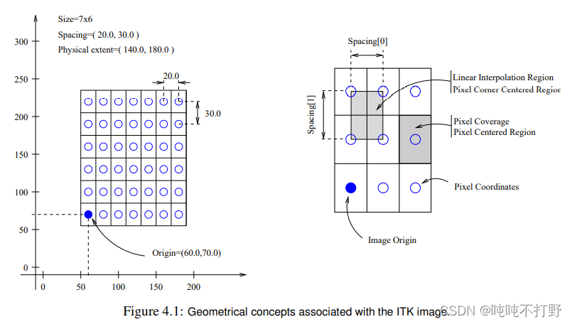
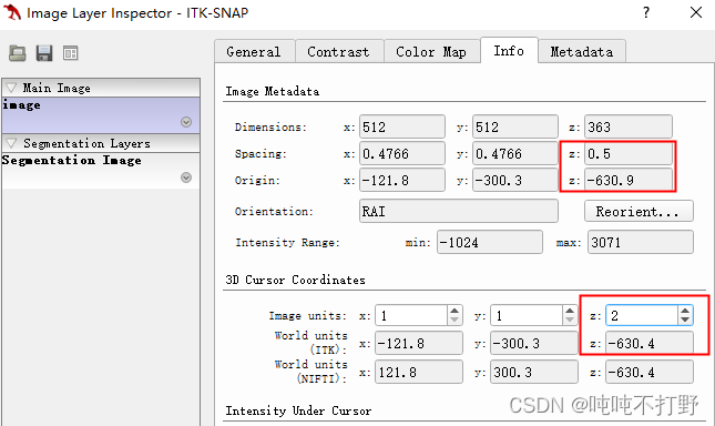
除了每个体素(voxel ) ( i , j , k ) (i,j,k) (i,j,k)的强度值,还会存储解剖坐标的原点(origin)和间距(spacing)
- origin(原点)表示图像第一个体素点(0,0,0)在解剖坐标系中的位置。(例如:100mm, 50mm, -25mm)
- spacing(间距)表示沿着每个轴体素之间的距离。(例如:1.5mm, 0.5mm, 0.5mm)
下面这个2D示例显示了origin和spacing的含义
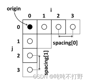
使用origin和spacing,图像坐标系中每个体素在解剖坐标系中的位置就可以被计算出来。
- ITK中,解剖坐标系一般称为物理空间(physical space),一般是用
itk::point来表示的 - 图像坐标系一般称为体素空间(voxel space),一般是用
itk::index来表示的
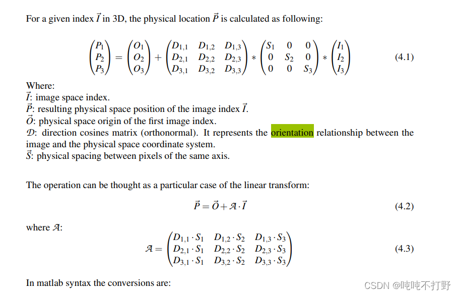
1.4 坐标系转换(图像坐标系到解剖坐标系)
1.4.1 理论
- 从
图像空间向量( i j k ) ′ (i\ j\ k)' (i j k)′(origin和体素点的连线)转为解剖空间向量( x → = ( x , y , z ) \overrightarrow{x} = (x,y,z) x=(x,y,z))是一个仿射变换的过程, - 需要一个
线性变换矩阵( A A A)以及一个平移向量( t → \overrightarrow{t} t) - 变换矩阵( A A A)是一个 3 × 3 3\times 3 3×3的矩阵,包含图像轴的方向和缩放等信息。
- t → \overrightarrow{t} t是一个 3 × 1 3\times 1 3×1的向量,一般等于origin,包含的是图像第一个体素的几何位置
整体转换公式可以表示为:
( x y z ) = ( A 11 A 12 A 13 A 21 A 22 A 23 A 31 A 32 A 33 ) ( i j k ) + ( t 1 t 2 t 3 ) \begin{pmatrix} x \\ y \\ z \\ \end{pmatrix}= \begin{pmatrix} A11&A12&A13 \\ A21&A22&A23 \\ A31&A32&A33 \\ \end{pmatrix} \begin{pmatrix} i \\ j \\ k \\ \end{pmatrix}+ \begin{pmatrix} t_1 \\ t_2 \\ t_3 \\ \end{pmatrix}
xyz
=
A11A21A31A12A22A32A13A23A33
ijk
+
t1t2t3
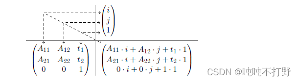
上式表示:线性转换是通过矩阵乘法完成的,平移是通过向量加法完成的。为了简化公式,可以把向量加法部分合并到矩阵乘法中去。即:
( x y z 1 ) = ( A 11 A 12 A 13 t 1 A 21 A 22 A 23 t 2 A 31 A 32 A 33 t 3 0 0 0 1 ) ( i j k 1 ) \begin{pmatrix} x \\ y \\ z \\ 1 \\ \end{pmatrix}= \begin{pmatrix} A11&A12&A13&t_1 \\ A21&A22&A23&t_2 \\ A31&A32&A33&t_3 \\ 0&0&0&1\\ \end{pmatrix} \begin{pmatrix} i \\ j \\ k \\ 1 \\ \end{pmatrix}
xyz1
=
A11A21A310A12A22A320A13A23A330t1t2t31
ijk1
上面的 4 × 4 4\times 4 4×4矩阵也也被称为 IJKtoLPS-matrix 或者 IJKtoRAS-matrix (取决于要转出的解剖系空间的方向),表示这个矩阵是用于从IJK(图像坐标系)转到LPS或者RAS
其实还可以更简单点,只是这里可能有其他考量(比如代码表示的时候,齐次可能会更好一些??),所以没有写成下面这样更简化的形式吧
( x y z ) = ( A 11 A 12 A 13 t 1 A 21 A 22 A 23 t 2 A 31 A 32 A 33 t 3 ) ( i j k ) \begin{pmatrix} x \\ y \\ z \\ \end{pmatrix}= \begin{pmatrix} A11&A12&A13&t_1 \\ A21&A22&A23&t_2 \\ A31&A32&A33&t_3 \\ \end{pmatrix} \begin{pmatrix} i \\ j \\ k \\ \end{pmatrix}
xyz
=
A11A21A31A12A22A32A13A23A33t1t2t3
ijk
1.4.1 例子
下图左边是 L ( P ) S L(P)S L(P)S方向的解剖空间(没有前后,只有上下和左右,二维示例),右侧是对应的图像坐标系
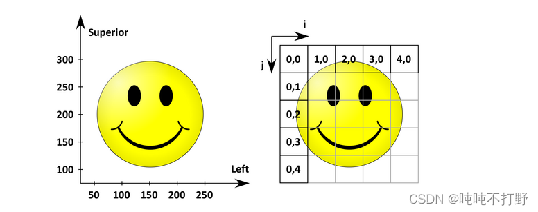
origin(解剖空间的第一个体素点的坐标)是( 50 m m ( i ) , 300 m m ( k ) 50mm(i),300mm(k) 50mm(i),300mm(k)),- 两个轴上的
spacing是( 50 m m , 50 m m 50mm,50mm 50mm,50mm)
( x y 1 ) = ( A 11 A 12 t 1 A 21 A 22 t 2 0 0 1 ) ( i j 1 ) \begin{pmatrix} x \\ y \\ 1\\ \end{pmatrix}= \begin{pmatrix} A11&A12&t_1 \\ A21&A22&t_2 \\ 0&0&1\\ \end{pmatrix} \begin{pmatrix} i \\ j \\ 1\\ \end{pmatrix} xy1 = A11A210A12A220t1t21 ij1
- 求出的 ( x , y ) (x,y) (x,y)就是 L ( P ) S L(P)S L(P)S的坐标(物理坐标),输入的 ( i , j ) (i,j) (i,j)是图像坐标系
- 计算过程类似这样
- 其实对于上面的公式来说,缺少 A A A矩阵和平移向量 t → \overrightarrow{t} t的值,可以使用待定系数法去计算。
- 很容易可以从图中知道,
- (0,0)对应的是(50,300),
- (0,1)对应的是(50,250)
- (1,0)对应的是(100,300)
- 把这三组点的值带进去,就可以求出 A A A矩阵和平移向量 t → \overrightarrow{t} t了
- 最后求出的结果, IJtoLS-matrix为
I J t o L S = ( A 11 A 12 t 1 A 21 A 22 t 2 0 0 1 ) = ( 50 0 50 0 − 50 300 0 0 1 ) IJtoLS=\begin{pmatrix} A11&A12&t_1 \\ A21&A22&t_2 \\ 0&0&1\\ \end{pmatrix}=\begin{pmatrix} 50&0&50\\ 0&-50&300 \\ 0&0&1\\ \end{pmatrix} IJtoLS= A11A210A12A220t1t21 = 50000−500503001 - 不难发现,平移向量 t → \overrightarrow{t} t就等于origin
- A A A转换矩阵,从下图的右侧变到左侧(图像坐标系变成解剖坐标系)时,没有发生旋转,所以只有对角线上有值(仅仅起到缩放轴,和改变方向的作用)
- 对角线
- 数值上等于 spacing。
其实是个比例,(50/1和50/1),因为图像坐标系的space是1,所以这里直接使用解剖坐标系的space就可以
确实就是求个公式,把右边的值变成左边的值。。不需要想的太复杂
矩阵操作是一次求3个轴/2个轴,可以1个1个轴去看,最后把公式整合成矩阵就行 - 方向上,
left和i方向相同,superior和j方向相反(沿着 i i i增大的方向 L e f t Left Left 轴是增加的, 沿着 j j j 增大的方向 S u p e r i o r Superior Superior轴是减小的),因此一个是50,另一个是-50(反方向)
- 数值上等于 spacing。
类似的,对于下图,
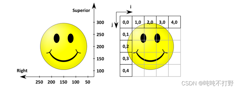
IJtoRS-matrix就等于
I J t o L S = ( A 11 A 12 t 1 A 21 A 22 t 2 0 0 1 ) = ( − 50 0 250 0 − 50 300 0 0 1 ) IJtoLS=\begin{pmatrix} A11&A12&t_1 \\ A21&A22&t_2 \\ 0&0&1\\ \end{pmatrix}=\begin{pmatrix} -50&0&250\\ 0&-50&300 \\ 0&0&1\\ \end{pmatrix} IJtoLS=
A11A210A12A220t1t21
=
−50000−5002503001
和IJtoLS-matrix有两个区别,
- 一个是origin(都是左上角,但是正方向变了,所以数值变了)
- left → right,所以第二行的50也变成反向的-50了
- RAS是右手坐标系,LAS是左手坐标系
1.5 结合itk-snap理解
-
ITK-SNAP的解剖坐标系是
RAI
-
ITK-SNAP图像的第一个点表示为(1,1,1),而不是(0,0,0)。第一个点对应的解剖坐标系位置就是
origin的值
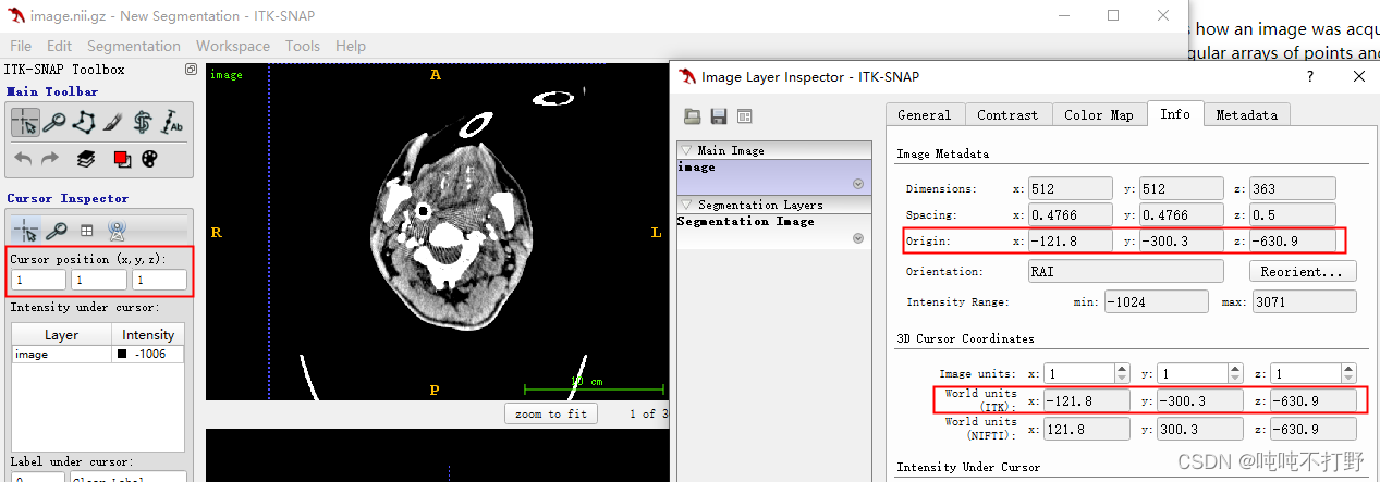
-
通过origin和spacing,可以计算出每个体素对应的世界坐标
注意
- 在ITK-SNAP中,解剖坐标被称为
World units(世界坐标),不需要过度纠结世界系坐标(笛卡尔坐标- x , y , z x,y,z x,y,z),知道指的是什么就可以,不要太纠结于名称
1.6 结合3D Slicer理解
1.7 左手坐标系和右手坐标系
1.7.1 医学影像里的左手坐标系和右手坐标系
这里规定拇指必须指向左右方向,食指必须指向前后方向,中指必须指向上下
- RAS是一个右手坐标系(拇指=R,食指=A,中指 = S),一般神经病学里常用。
- 手可能不是很好比划这个动作,
- LAS是一个左手坐标系,一般放射学里常用
- 左手坐标系和右手坐标系在执行矩阵和向量的乘法运算时很重要,通常右手坐标系更常使用(也可以进行调整来使用左手坐标系)
参考: Orientation and Voxel-Order Terminology: RAS, LAS, LPI, RPI, XYZ and All That
1.7.2 一般所说的左右手坐标系
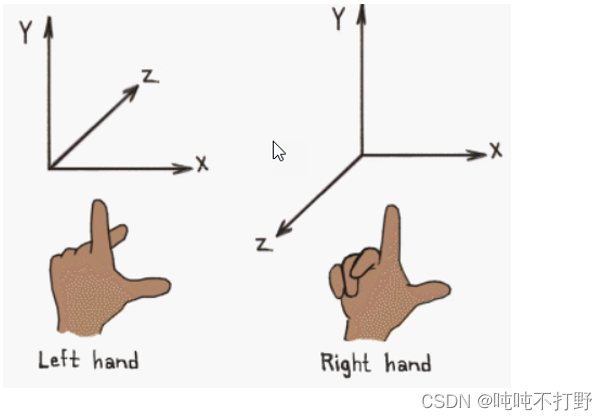
拇指只能是 X轴,食指只能是 Y轴,中指只能是 Z轴,是为了定义一种区分标准,让你可以区别什么是右手坐标系,什么是左手坐标系。(有其他区分标准)。
在这种区分标准下,上面的坐标系只能用左手或者右手做出来。
参考内容:
- 知乎:左手坐标系 右手坐标系 区别
- 知乎:左手坐标系 vs 右手坐标系
- 博客园:左手坐标系和右手坐标系
其他参考:
-
Understanding coordinate systems and DICOM for deep learning medical image analysis
-
Orientation and Voxel-Order Terminology: RAS, LAS, LPI, RPI, XYZ and All That
-
Section 11. Direction Matrices - This section is in construction
-
http://itksnap.org/pmwiki/pmwiki.php?n=Documentation.DirectionMatrices
坐标系转换:
- Coordinate System Conversion Between ITK and Slicer3
- slicer软件中RAS转换为像素坐标方法
- Building the ijk to RAS transform from a nrrd file
- Understanding 3D medical image orientation for programmers
itkwidget