目录

0. 概要
本实验利用Simulink Coder将系统模型中子系统生成为可以重复调用的独立的函数,这样能够使得基于模型的开发流程更加流畅高效。关于基于Simulink Coder自动生成代码的基本流程可以参考:
Matlab/Simulink自动生成C代码实验(基于一个简单信号滤波例子)
软件环境:Windows10,Matlab2021b中文版
1. 原始的模型及其代码生成
1.1 模型
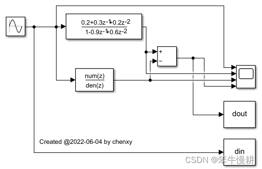
以下是为了本次实验而搭建的一个简单模型(具体做什么处理并不是要点,只是一个信号经过两路滤波,然后两路滤波结果相减得到输出而已)。
1.2 滤波器参数初始化
滤波器参数初始化写在脚本“AtomicUnit_example_initset.m”中,然后以模型回调的方式进行调用,如下图所示:
close all; clear; clc

% 滤波器1参数设置
a1 = [0.2 0.3 0.2];
b1 = [-0.9    0.6];

% 滤波器2参数设置
a2 = [1];
b2 = [1,0.5]; 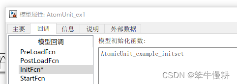
1.3 参考数据保存
为了方便与生成的C模型进行对比验证,这里将模型的输入和输出通过两个“To Workspace”模块输入到桌面,然后通过StopFcn回调将数据保存到mat文件中:

AtomicUnit_ex1_save.m的内容如下:
save('AtomUnit_ex1_sim.mat','din','dout');1.4 C代码生成及验证
采用Simulink Coder进行C代码生成(基本设置方式参见Matlab/Simulink自动生成C代码实验(基于一个简单信号滤波例子)),生成完后,在matlab命令行执行:
!AtomUnit_ex1.exe
该exe生成的输入输出数据会存储在另一个mat文件中:AtomUnit_ex1.mat
执行以下脚本可以确认C模型的输出数据与Simulink模型输出数据是一致的(由于是浮点运算,可以会存在比如说10的负10次方以下的误差,可以忽略)。
close all; clear; clc;

% Simulink模型仿真生成的数据
load("AtomUnit_ex1_sim.mat");
% 生成C代码时配套生成的exe文件运行产生的数据
load("AtomUnit_ex1.mat");

diff = dout - rt_dout;
fprintf(1,'The maximum difference = %f, relative error = %f\n',...
    max(abs(diff)),max(abs(diff))/max(abs(dout)));

figure;
plot(dout); hold on;
plot(rt_dout);
1.5 遗留问题
以上C模型生成和验证流程虽然很方便,但是有一个小瑕疵。Simulink Coder在生成代码时是将整个模型展平(flattern)了,将包括数据输入、数据输出等属于验证平台的处理以及数据处理核心算法(可以理解为待验证的实现对象)部分的处理都放在***_step函数中了,如下所示:
/* Model step function */
void AtomUnit_ex1_step(void)
{
  /* Sin: '<Root>/Sine Wave' */
  AtomUnit_ex1_B.SineWave = sin(AtomUnit_ex1_M->Timing.t[0]);

  /* S-Function (sfix_udelay): '<S1>/Tapped Delay' */
  AtomUnit_ex1_B.TappedDelay[0] = AtomUnit_ex1_DW.TappedDelay_X[0];
  AtomUnit_ex1_B.TappedDelay[1] = AtomUnit_ex1_DW.TappedDelay_X[1];

  /* Gain: '<S1>/DenCoef' */
  AtomUnit_ex1_B.DenCoef = -0.9 * AtomUnit_ex1_B.TappedDelay[0] + 0.6 *
    AtomUnit_ex1_B.TappedDelay[1];

  /* Sum: '<S1>/Sum' */
  AtomUnit_ex1_B.Sum = AtomUnit_ex1_B.SineWave - AtomUnit_ex1_B.DenCoef;

  /* Gain: '<S1>/NumCoef' incorporates:
   *  SignalConversion generated from: '<S1>/NumCoef'
   */
  AtomUnit_ex1_B.NumCoef = (0.2 * AtomUnit_ex1_B.Sum + 0.3 *
    AtomUnit_ex1_B.TappedDelay[0]) + 0.2 * AtomUnit_ex1_B.TappedDelay[1];

  /* DiscreteFilter: '<Root>/Discrete Filter' */
  AtomUnit_ex1_DW.DiscreteFilter_tmp = AtomUnit_ex1_B.SineWave - 0.5 *
    AtomUnit_ex1_DW.DiscreteFilter_states;

  /* DiscreteFilter: '<Root>/Discrete Filter' */
  AtomUnit_ex1_B.DiscreteFilter = AtomUnit_ex1_DW.DiscreteFilter_tmp;

  /* Sum: '<Root>/Subtract' */
  AtomUnit_ex1_B.Subtract = AtomUnit_ex1_B.NumCoef -
    AtomUnit_ex1_B.DiscreteFilter;

  /* ToWorkspace: '<Root>/To Workspace1' */
  rt_UpdateLogVar((LogVar *)(LogVar*)
                  (AtomUnit_ex1_DW.ToWorkspace1_PWORK.LoggedData),
                  &AtomUnit_ex1_B.Subtract, 0);

  /* ToWorkspace: '<Root>/To Workspace2' */
  rt_UpdateLogVar((LogVar *)(LogVar*)
                  (AtomUnit_ex1_DW.ToWorkspace2_PWORK.LoggedData),
                  &AtomUnit_ex1_B.SineWave, 0);

  /* Matfile logging */
  rt_UpdateTXYLogVars(AtomUnit_ex1_M->rtwLogInfo, (AtomUnit_ex1_M->Timing.t));

  /* Update for S-Function (sfix_udelay): '<S1>/Tapped Delay' */
  AtomUnit_ex1_DW.TappedDelay_X[1] = AtomUnit_ex1_DW.TappedDelay_X[0];
  AtomUnit_ex1_DW.TappedDelay_X[0] = AtomUnit_ex1_B.Sum;

  /* Update for DiscreteFilter: '<Root>/Discrete Filter' */
  AtomUnit_ex1_DW.DiscreteFilter_states = AtomUnit_ex1_DW.DiscreteFilter_tmp;

  /* signal main to stop simulation */
  {                                    /* Sample time: [0.0s, 0.0s] */
    if ((rtmGetTFinal(AtomUnit_ex1_M)!=-1) &&
        !((rtmGetTFinal(AtomUnit_ex1_M)-AtomUnit_ex1_M->Timing.t[0]) >
          AtomUnit_ex1_M->Timing.t[0] * (DBL_EPSILON))) {
      rtmSetErrorStatus(AtomUnit_ex1_M, "Simulation finished");
    }
  }

  /* Update absolute time for base rate */
  /* The "clockTick0" counts the number of times the code of this task has
   * been executed. The absolute time is the multiplication of "clockTick0"
   * and "Timing.stepSize0". Size of "clockTick0" ensures timer will not
   * overflow during the application lifespan selected.
   * Timer of this task consists of two 32 bit unsigned integers.
   * The two integers represent the low bits Timing.clockTick0 and the high bits
   * Timing.clockTickH0. When the low bit overflows to 0, the high bits increment.
   */
  if (!(++AtomUnit_ex1_M->Timing.clockTick0)) {
    ++AtomUnit_ex1_M->Timing.clockTickH0;
  }

  AtomUnit_ex1_M->Timing.t[0] = AtomUnit_ex1_M->Timing.clockTick0 *
    AtomUnit_ex1_M->Timing.stepSize0 + AtomUnit_ex1_M->Timing.clockTickH0 *
    AtomUnit_ex1_M->Timing.stepSize0 * 4294967296.0;

  {
    /* Update absolute timer for sample time: [0.1s, 0.0s] */
    /* The "clockTick1" counts the number of times the code of this task has
     * been executed. The resolution of this integer timer is 0.1, which is the step size
     * of the task. Size of "clockTick1" ensures timer will not overflow during the
     * application lifespan selected.
     * Timer of this task consists of two 32 bit unsigned integers.
     * The two integers represent the low bits Timing.clockTick1 and the high bits
     * Timing.clockTickH1. When the low bit overflows to 0, the high bits increment.
     */
    AtomUnit_ex1_M->Timing.clockTick1++;
    if (!AtomUnit_ex1_M->Timing.clockTick1) {
      AtomUnit_ex1_M->Timing.clockTickH1++;
    }
  }
}
这样的话,有一个问题就是,核心算法处理所对应的C模型虽然得到了验证,但是不能直接用于系统开发(手动地将相关部分挖出来封装成函数的方式虽然可以做,但是很麻烦且容易出错)。解决方案参见下一节。
2. 将核心处理封装成一个子系统
2.1 子系统封装
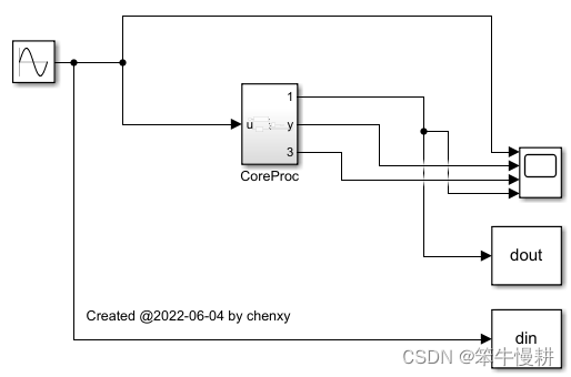
选中核心处理所包含的三个子模块(两个滤波器和一个减法模块),右键下拉菜单选择“基于所选内容创建子系统”,模型顶层模型将变成如下所示(子系统缺省名为SubSystem,下面改为CoreProc了):
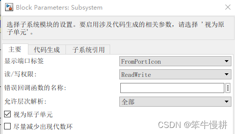
2.2 将子系统配置为原子单元
为了将子系统生成为独立的可重用函数,还需要进一步设置如下。右键点击子系统从下拉菜单中选择“模块参数”,弹出如下对话框,勾选“视为原子单元”(缺省为“尽量减少出现代数环”)。
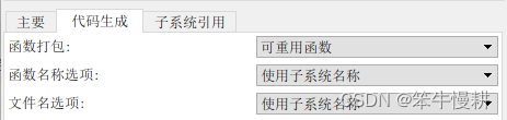
然后再切换到“代码生成”页,缺省状态如下所示:

按照如下方式修改:
还有一个“子系统引用”,这个是另外一项内容,本文暂且不去招惹,另文讨论。
2.3 代码生成及验证
同样,先执行仿真生成参考数据,存储于AtomUnit_ex2_sim.mat中,然后,切换到“C CODE”点击“Build”即可生成代码(设置继承上面的实验,不必修改)。从生成的代码来看,可以看出多出来两个源文件:CoreProc.c和CoreProc.h。
打开顶层的源文件,可以看到现在step()函数调用了AtomUnit_ex2_CoreProc()等函数。这样,这些函数由于是以可重用函数的形式生成的,经过验证后便可以在其它的系统中使用了。
/* Model step function */
void AtomUnit_ex2_step(void)
{
  /* Sin: '<Root>/Sine Wave' */
  AtomUnit_ex2_B.SineWave = sin(AtomUnit_ex2_M->Timing.t[0]);

  /* ToWorkspace: '<Root>/To Workspace2' */
  rt_UpdateLogVar((LogVar *)(LogVar*)
                  (AtomUnit_ex2_DW.ToWorkspace2_PWORK.LoggedData),
                  &AtomUnit_ex2_B.SineWave, 0);

  /* Outputs for Atomic SubSystem: '<Root>/CoreProc' */
  AtomUnit_ex2_CoreProc(AtomUnit_ex2_B.SineWave, &AtomUnit_ex2_B.CoreProc,
                        &AtomUnit_ex2_DW.CoreProc);

  /* End of Outputs for SubSystem: '<Root>/CoreProc' */

  /* ToWorkspace: '<Root>/To Workspace1' */
  rt_UpdateLogVar((LogVar *)(LogVar*)
                  (AtomUnit_ex2_DW.ToWorkspace1_PWORK.LoggedData),
                  &AtomUnit_ex2_B.CoreProc.Subtract, 0);

  /* Matfile logging */
  rt_UpdateTXYLogVars(AtomUnit_ex2_M->rtwLogInfo, (AtomUnit_ex2_M->Timing.t));

  /* Update for Atomic SubSystem: '<Root>/CoreProc' */
  AtomUnit_ex2_CoreProc_Update(&AtomUnit_ex2_B.CoreProc,
    &AtomUnit_ex2_DW.CoreProc);

  /* End of Update for SubSystem: '<Root>/CoreProc' */
  ......
生成完的模型可以以与上一节完全相同的方式进行验证。
基于Embedded Coder生成C代码与基于Simulink Coder的代码生成大同小异,但是由于嵌入式代码的运行环境和运行方式不同,开发流程还是有一些显著的区别。基于Embedded Coder生成C代码的实验将在下一篇来介绍,敬请期待。