时间在2021年2月2日,寒假放假在家好好学一学nRF52840
学了一点PPI组件,感觉用不上, 就没放了, 后面如果用上才重新学
昨天写了一天的PPI BUG代码,还是硬着头才发现代码少了
开发板:初雪的100出头那块 NRF52840 EVAL KIT
下载工具:JINLK V11(最好是JLINK V9以上 也有人用JLINK OB也行,其他的下载器诸如STLINK,DAP不建议用)
版本号: KEIL5编程环境,CMSIS为5.3.0, NRF52840的CMSIS为8.35.0

参考资料: NRF52840-Eval-Kit-Schematic.pdf(原理图)
nRF5_SDK_17.0.2_d674dde(官方例程)
nRF5_SDK_17.0.0_offline_doc(官方文档)
nRF52840_PS_v1.1.pdf(官方数据手册)
- RTC 实时计数器 32.768KHz外部低频晶振
- nRF52 处理器内部的 RTC 是实时计数器,其是 Real-time counter 的缩写,是在低频时钟源LFCLK 上提供一个通用的低功耗定时器。区别于单片机中常使用的实时时钟,实时时钟的缩写也是RTC,其是 Real-time Clock 的缩写。实时时钟是为人们提供精确的实时时间或者为电子系统提供精确的时间基准。因此要注意本章内容讲述的 RTC 为实时计数器,它与实时时钟是有区别的
- nRF52 处理器内部的 RTC 模块具有 RTC0、RTC1、RTC2 三个,每个模块其内部具有一个24 位计数器、12 位预分频器、捕获/比较寄存器和一个滴答事件生成器用于低功耗、无滴答 RTOS的实现。
添加驱动文件

大概在
..\..\..\SDK\components\drivers_nrf\nrf_soc_nosd\nrf_soc.c
..\..\..\..\..\..\modules\nrfx\drivers\src\nrfx_power.c
..\..\..\SDK\integration\nrfx\legacy\nrf_drv_clock.c
添加SDK_CONFIG

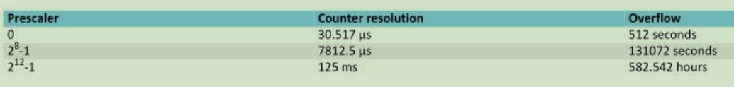
分频 跳动一次时间 最大计时时间
实现功能: 滴答定时器点灯
添加头文件:
#include "nrf_drv_rtc.h"
#include "nrf_drv_clock.h"
配置低速时钟:
	nrf_drv_clock_init(); // 开启时钟
	nrf_drv_clock_lfclk_request(NULL); // 请求低频时钟请求,没有配置事件中断
配置RTC:
nrf_drv_rtc_config_t config = NRF_DRV_RTC_DEFAULT_CONFIG;
	config.prescaler = 0; // 不分频,就用32768为时钟,30.517us一次

然后定义一下 使用RTC0(RTC有0,1,2共3个)
const nrf_drv_rtc_t rtc = NRF_DRV_RTC_INSTANCE(0); /**< Declaring an instance of nrf_drv_rtc for RTC0. */继续写代码:( 这个代码不行,后面有修改)
	nrf_drv_rtc_init(&rtc, &config, My_RTCInterrupt); // 使用RTC0,写入结构体,
	nrf_drv_rtc_tick_enable(&rtc,true); //开启滴答定时器事件中断

	//使用RTC0 , CC为通道0, 比较值为,  比较成功后触发中断
	// 33 * 30.517u = 1.007061ms
	nrf_drv_rtc_cc_set(&rtc,0,33,true); //大概为1ms

	nrf_drv_rtc_enable(&rtc); //启动RTC定时器
我用33 * 30.517u = 1.007061ms 约为1ms 就触发比较事件一次
测试后发现, 不能这么做
比较完1ms之后就无法重新计数1ms了, 无法恢复正常,只能使用1次,所以不要用比较了,那么就只用滴答定时器功能,不要输出比较定时
因为要定时1ms 于是修改为由32768分频出来的1ms
1 / 32768 *33 = 1ms(约等于)
代码修改为:
nrf_drv_clock_init(); // 开启时钟
	nrf_drv_clock_lfclk_request(NULL); // 请求低频时钟请求,没有配置事件中断

    nrf_drv_rtc_config_t config = NRF_DRV_RTC_DEFAULT_CONFIG; //使用SDK_CONFIG那边的默认配置
	config.prescaler = 33; // 1/ (32768/33) = 1ms

	nrf_drv_rtc_init(&rtc, &config, My_RTCInterrupt); // 使用RTC0,写入结构体,中断函数
	nrf_drv_rtc_tick_enable(&rtc,true); //开启滴答定时器事件中断
	nrf_drv_rtc_enable(&rtc); //启动RTC定时器
中断函数为:
void My_RTCInterrupt(nrfx_rtc_int_type_t int_type)
{
	static uint16_t flag500ms = 0;

    if (int_type == NRF_DRV_RTC_INT_COMPARE0)
    { //无法恢复正常,只能使用1次,所以不要用比较了
//		nrf_gpio_pin_toggle(LED0);
    }

    //滴答中断 这边是 1/ 32768 * 33 = 1ms
    else if (int_type == NRF_DRV_RTC_INT_TICK)
    {
		if( ++flag500ms == 500 )
		{
			nrf_gpio_pin_toggle(LED3);
			flag500ms = 0;
		}
    }
}
整体代码为:
#include <stdbool.h>
#include <stdint.h>
#include "nrf_delay.h"
#include "nrf_gpio.h"
#include "nrf_drv_gpiote.h"

#include "nrf_uart.h"
#include "app_uart.h"
#include "nrf_drv_timer.h"

#include "nrf_drv_rtc.h"
#include "nrf_drv_clock.h"

uint32_t LED0,LED1,LED2,LED3;
uint32_t KEY0,KEY1,KEY2,KEY3;

void KEY_Interrupt(nrfx_gpiote_pin_t pin, nrf_gpiote_polarity_t action);


#define MAX_TEST_DATA_BYTES     (15U)                /**< max number of test bytes to be used for tx and rx. */
#define UART_TX_BUF_SIZE 256                         /**< UART TX buffer size. */
#define UART_RX_BUF_SIZE 256                         /**< UART RX buffer size. */

void uart_interrupt(app_uart_evt_t * p_event);


const nrf_drv_timer_t My_Timer0 = NRF_DRV_TIMER_INSTANCE(4);
// 0~4共5个定时计数器
void My_Timer0_Interrupt(nrf_timer_event_t event_type,
									void  * p_context);


const nrf_drv_rtc_t rtc = NRF_DRV_RTC_INSTANCE(0); /**< Declaring an instance of nrf_drv_rtc for RTC0. */
void My_RTCInterrupt(nrfx_rtc_int_type_t int_type);


/**
 * @brief Function for application main entry.
 */
int main(void)
{
	nrf_drv_gpiote_in_config_t key_ex_config; //按键中断配置用

	LED0 =  NRF_GPIO_PIN_MAP(0,13);
	LED1 =  NRF_GPIO_PIN_MAP(0,14);
	LED2 =  NRF_GPIO_PIN_MAP(1,9);
	LED3 =  NRF_GPIO_PIN_MAP(0,16);

	KEY0 =  NRF_GPIO_PIN_MAP(0,11);
	KEY1 =  NRF_GPIO_PIN_MAP(0,24);
	KEY2 =  NRF_GPIO_PIN_MAP(0,20);
	KEY3 =  NRF_GPIO_PIN_MAP(0,17);

	nrf_gpio_cfg_output(LED0);
	nrf_gpio_cfg_output(LED1);
	nrf_gpio_cfg_output(LED2);
	nrf_gpio_cfg_output(LED3);

	nrf_gpio_pin_set(LED0);
	nrf_gpio_pin_set(LED1);
	nrf_gpio_pin_set(LED2);
	nrf_gpio_pin_set(LED3);

	nrf_gpio_cfg_input(KEY0,NRF_GPIO_PIN_PULLUP );
	nrf_gpio_cfg_input(KEY1,NRF_GPIO_PIN_PULLUP );
	nrf_gpio_cfg_input(KEY2,NRF_GPIO_PIN_PULLUP );
	nrf_gpio_cfg_input(KEY3,NRF_GPIO_PIN_PULLUP );

	nrf_drv_gpiote_init();//启动GPIOTE时钟,可以这么说

	key_ex_config.hi_accuracy=false; // 启用低精确度PORT事件
	key_ex_config.pull = NRF_GPIO_PIN_PULLUP ; //上啦
	key_ex_config.sense = NRF_GPIOTE_POLARITY_HITOLO ;//下降沿

	nrf_drv_gpiote_in_init(KEY0, &key_ex_config, KEY_Interrupt);
	nrf_drv_gpiote_in_init(KEY1, &key_ex_config, KEY_Interrupt);
	nrf_drv_gpiote_in_init(KEY2, &key_ex_config, KEY_Interrupt);
	nrf_drv_gpiote_in_init(KEY3, &key_ex_config, KEY_Interrupt);

	nrf_drv_gpiote_in_event_enable(KEY0, true);//启动KEY0中断
	nrf_drv_gpiote_in_event_enable(KEY1, true);//启动KEY1中断
	nrf_drv_gpiote_in_event_enable(KEY2, true);//启动KEY2中断
	nrf_drv_gpiote_in_event_enable(KEY3, true);//启动KEY3中断


    const app_uart_comm_params_t comm_params =
      {
          8,
          6,
          0,
          0,
          APP_UART_FLOW_CONTROL_DISABLED,
          false,
          NRF_UART_BAUDRATE_115200
      };
	uint32_t err_code;
    APP_UART_FIFO_INIT(&comm_params,
                         UART_RX_BUF_SIZE,
                         UART_TX_BUF_SIZE,
                         uart_interrupt,
                         APP_IRQ_PRIORITY_LOWEST,
                         err_code);

	nrf_drv_timer_config_t timer_cfg = NRF_DRV_TIMER_DEFAULT_CONFIG;	//定义定时器结构体
	timer_cfg.bit_width= NRF_TIMER_BIT_WIDTH_16 ;
	timer_cfg.frequency= NRF_TIMER_FREQ_1MHz;
	timer_cfg.interrupt_priority= 7;
	timer_cfg.mode=NRF_TIMER_MODE_TIMER ;

	nrf_drv_timer_init(&My_Timer0, &timer_cfg,My_Timer0_Interrupt);

	uint32_t time_ticks ;
	time_ticks = nrfx_timer_ms_to_ticks(&My_Timer0, 1); //算出1ms需要计数多少次

	nrf_drv_timer_extended_compare( //       time_ticks可以直接写1000
         &My_Timer0, NRF_TIMER_CC_CHANNEL5 , time_ticks, NRF_TIMER_SHORT_COMPARE5_CLEAR_MASK, true);
/* 使用定时器实例0, CC通道0(定时器0可以用0~3), 比较时间为time_ticks次(1000次),
	清除比较器CC0的任务, 开启定时器0CC通道 */

	nrf_drv_timer_enable(&My_Timer0);


	nrf_drv_clock_init(); // 开启时钟
	nrf_drv_clock_lfclk_request(NULL); // 请求低频时钟请求,没有配置事件中断

    nrf_drv_rtc_config_t config = NRF_DRV_RTC_DEFAULT_CONFIG; //使用SDK_CONFIG那边的默认配置
	config.prescaler = 33; // 1/ (32768/33) = 1ms

	nrf_drv_rtc_init(&rtc, &config, My_RTCInterrupt); // 使用RTC0,写入结构体,中断函数
	nrf_drv_rtc_tick_enable(&rtc,true); //开启滴答定时器事件中断
	nrf_drv_rtc_enable(&rtc); //启动RTC定时器


	while(1)
	{
//		printf("hello world! \r\n");
	}

}

void KEY_Interrupt(nrfx_gpiote_pin_t pin, nrf_gpiote_polarity_t action)
{
	if(KEY0 == pin)
		nrf_gpio_pin_toggle(LED0);
	if(KEY1 == pin)
		nrf_gpio_pin_toggle(LED1);
	if(KEY2 == pin)
		nrf_gpio_pin_toggle(LED2);
	if(KEY3 == pin)
		nrf_gpio_pin_toggle(LED3);
}

void uart_interrupt(app_uart_evt_t * p_event)
{
	uint8_t dat;
    if (p_event->evt_type == APP_UART_COMMUNICATION_ERROR)
    {
        APP_ERROR_HANDLER(p_event->data.error_communication);
    }
    else if (p_event->evt_type == APP_UART_FIFO_ERROR)
    {
        APP_ERROR_HANDLER(p_event->data.error_code);
    }

    else if (p_event->evt_type == APP_UART_DATA_READY)
	{//数据已到达串口 , 可以读数据了
		app_uart_get(&dat); //读取数据
		app_uart_put(dat); // 原路发回
	}
    else if (p_event->evt_type == APP_UART_TX_EMPTY)
	{//发送完成
		//发送完成不知道要做什么的,可以点个灯提醒
		nrf_gpio_pin_toggle(LED0);
	}
}

void My_Timer0_Interrupt(nrf_timer_event_t event_type,
									void  * p_context) //1ms
{
	static uint16_t flag_500ms;
    switch (event_type)
    {
        case NRF_TIMER_EVENT_COMPARE5: // 匹配到了1ms的次数了
			if( ++flag_500ms == 500 ) //500ms
			{
				nrf_gpio_pin_toggle(LED1);
				flag_500ms = 0;
			}
            break;

        default:
            //Do nothing.
            break;
    }
}


void My_RTCInterrupt(nrfx_rtc_int_type_t int_type)
{
	static uint16_t flag500ms = 0;

    if (int_type == NRF_DRV_RTC_INT_COMPARE0)
    { //无法恢复正常,只能使用1次,所以不要用比较了
//		nrf_gpio_pin_toggle(LED0);
    }

    //滴答中断 这边是 1/ 32768 * 33 = 1ms
    else if (int_type == NRF_DRV_RTC_INT_TICK)
    {
		if( ++flag500ms == 500 )
		{
			nrf_gpio_pin_toggle(LED3);
			flag500ms = 0;
		}
    }
}


/**
 *@}
 **/
烧录后如果卡机,那么打开串口 或者注释串口代码 即可正常启动
启动后会发现, RTC的定时器和 真正的高速时钟定时器的定时时间有误差,且误差越积累越大
但是, 在低功耗的情况下, 滴答定时器的粗略延时已经足够跑任务了, 因此专用的定时器在低功耗的情况下,就休息一波吧