1. Camera Models and Distortion Models
For current, there are several camera model and lens distortion model products.
1.1 Camera Model
for camera models, follows is the main type:
- pinhole camera model (pinhole)
(intrinsics vector: [fu fv pu pv]) - omnidirectional camera model (omni)
(intrinsics vector: [xi fu fv pu pv]) - double sphere camera model (ds)
(intrinsics vector: [xi alpha fu fv pu pv]) - extended unified camera model (eucm)
(intrinsics vector: [alpha beta fu fv pu pv])
The intrinsics vector contains all parameters for the model:
- fu, fv: focal-length
- pu, pv: principal point
- xi: mirror parameter (only omni)
- xi, alpha: double sphere model parameters (only ds)
- alpha, beta: extended unified model parameters (only eucm)
Here, only focus on pinhole camera, which is the most popular camera image type. Detail information can be found in:https://github.com/ethz-asl/kalibr/wiki/supported-models
1.2 Lens Distortion Model
General lens distortion model as follows:
- radial-tangential (radtan)
(distortion_coeffs: [k1 k2 r1 r2]) - equidistant (equi)
(distortion_coeffs: [k1 k2 k3 k4]) - fov (fov)
(distortion_coeffs: [w]) - none (none)
(distortion_coeffs: [])
2. Severa Coordinates in Camera Calibration
Just think about the pinhole camera model and radial and tangential lens distortion model, so, there are four coordinates in camera calibration, World Frame, Camera Frame, Image Frame, Pixel Frame. Look at the fiugre 1, is the world frame point,
is the camera frame, (x, y) is the image frame and the (u, v) is the pixel frame.
Figure 1 Image System

2.1 Word Frame to Camera Frame
For these two different frames, there exist a rotation matrix(R) and translation vetor(t), which can used to transform one point to antoher frame.
 (1)
(1)

the R is a 3*3 orthogonal matrix.
2.2 Camera Frame to Image Frame
Given is the focal length,
 (2)
(2)
Use the homogeneous coordinates and matrix to express it as follows:
 (3)
(3)
2.3 Image Frame to Pixel Frame

Figure 2 Image Frame and Pixel Frame
x and y expressed in pysichal unit:mm, and (u, v) expressed in pixels, given are the phsichal length in millimeter per pixel, we can get:
 (4)
(4)
means the image frame origin point's coordinates in Pixel Frame.
Thus, we use the homogeneous coordinates to express it as follows:
 (5)
(5)
Finally, join the equation(1) to (5), we can get the follows formular:
 (6)
(6)
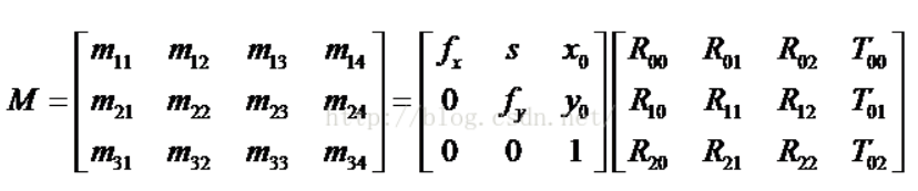
Then, do some mergence, it shows as follows:
 (7)
(7)
is the focal length in pixel at x or y axis respectively.
is the internal parameter of the camera, and
is the external paramers of the camera.
2.4 Undistortion to Distortion Frame
From formular(7), it gots only undistortion cooridnates, but in fact, almost all the lens have distortion for both radial and tangential direction. Given (x, y) is the distortioned pxiel coordiantes. The corrected pixel coordinates as follows:
2.4.1 Raidal Distortion
 (8)
(8)
2.4.2 Tangential Distortion
 (9)
(9)
combined formular(7), u is the and v is the
, and (x, y) form the formular(8-9) are the acutally distorted image pixel cooridinates.
are the radial distortion parameters,
are the tangential distortion parameters, where r is
, and
is the
in formular(6).
3. Calibration Method
3.1 Plate Calibration
This method is proposed by Zhang Zhengyou, it's a practical and popular method, both OpenCV and Matlab support this method. Detail information can be found in this paper[A Flexible New Technique for Camera]
3.2 Setero Calibration Steps
Just think about two cameras, left and right.

4. Attention With Camera Calibration
- Two cameras capture the target(chessboard) synchonized, or the after the target stop moving.
- Take a least five different pose and distance images.
- Take a leat 40 images for each camera.
- The taken images should spread the vison filed of the lens.
- If want high calibration accuracy, the printed chessboad also need high printed accuracy, such as under 10 micro meters.
- Chosse suitable lens distortion model for different lens. Generally, choose the fov model when the HFOV is larger than 90 degeree.
5. Depth Information Generation
There two method to get the depth information for binocular camera. One is use the parallex and baseline, another use the Least Squares Equation. First use the distortion parameters to undistort the images, then extract the match points from both camera's images. Finally use follows method to got the 3D position.
5.1 Optical Axis Parallel Model
This method works based on the two camera's optical are parallel and the image plane is the same plane. T is the base line, f is the focal length, P is the objective point.


 (10)
(10)
 (11)
(11)
Combined formular(9) and (10), we got the 3D coordinates. But in reality, this assumption is not practical.
5.2 Least Square Equation Model
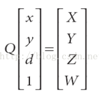
So, for generic usage of binocular vision. We use follows formular:
 (12)
(12)
 (13)
(13)
 (20)
(20)
 (21)
(21)
 (22)
(22)
Based on the formular(22), use the least square equation method to solve the (X, Y, Z).
6. 3D Point Cloud Reconstruction
Once we got the 3D point cloud, we may do point cloud registration or align, filter, mesh etc.