Introduction
This example shows how to generate a downlink transmission including EPDCCH, EPDCCH Demodulation Reference Signal (DMRS), Cell-Specific Reference Signal (CRS) and Channel State Information Reference Signal (CSI-RS). The output of the example is a resource grid populated with the transmitted channels and an OFDM modulated time-domain waveform which transmits that resource grid
Cell-wide settings
% Number of downlink resource blocks corresponding to 5MHz bandwidth
enb.NDLRB = 25;

% Duplexing mode: 'FDD' or 'TDD'
enb.DuplexMode = 'FDD';

% Number of Cell-specific Reference Signal (CRS) antenna ports
enb.CellRefP = 1;

% Subframe number
enb.NSubframe = 0;

% Cyclic prefix length: 'Normal' or 'Extended'
enb.CyclicPrefix = 'Normal';

% Frame number
enb.NFrame = 0;

% Cell identity
enb.NCellID = 0;

% Channel State Information Reference Signal (CSI-RS) subframe schedule
enb.CSIRSPeriod = 'On';

% Configuration index of the CSI-RS
enb.CSIRSConfig = 1;

% Number of CSI-RS antenna ports in use with this configuration
enb.CSIRefP = 2;

% Zero-Power CSI-RS subframe schedule
enb.ZeroPowerCSIRSPeriod = 'Off';
EPDCCH Configuration
A structure chs is created, containing parameters relevant to the transmission of a DCI message which will be coded and modulated on the EPDCCH channel. Unlike the structure enb above which configures cell-wide settings, the structure here configures channel-specific settings for the transmission of a particular channel, in this case the EPDCCH.
% DCI format to send on the EPDCCH
chs.DCIFormat = 'Format1A';

% Radio Network Temporary Identifier (RNTI)
chs.RNTI = 1;

% Transmission type: 'Localized' or 'Distributed'
chs.EPDCCHType = 'Localized';

% Zero-based indices of PRB pair set associated with EPDCCH search space
chs.EPDCCHPRBSet = 4:5;

% Initial transmission symbol for EPDCCH transmission
chs.EPDCCHStart = 2;

% Scrambling identity for the EPDCCH
chs.EPDCCHNID = 0;

% EPDCCH format
chs.EPDCCHFormat = 1;
Subframe Resource Grid Creation
In this example, the 3rd dimension (planes) of this resource grid are intended to represent physical antennas. The mapping between antenna ports and physical antennas for the various channels and signals used in this example will be described when the channels and signals are mapped to this resource grid.
In this example, the 3rd dimension (planes) of this resource grid are intended to represent physical antennas. The mapping between antenna ports and physical antennas for the various channels and signals used in this example will be described when the channels and signals are mapped to this resource grid.
maxEpdcchPorts = 2;
nTxAnts = max([enb.CSIRefP enb.CellRefP maxEpdcchPorts]);
subframe = lteDLResourceGrid(enb,nTxAnts);
DCI Message Creation
A DCI message of the format indicated by chs.DCIFormat is created using the function lteDCI. The output structure dci represents the DCI message as described in TS36.212 Section 5.3.3.1.
% Create a DCI message
[dci,dciBits] = lteDCI(enb,chs);
EPDCCH Candidate Selection
The EPDCCH is transmitted in an "EPDCCH candidate", a set of Enhanced Control Channel Elements (ECCEs). Each ECCE maps onto a set of Enhanced Resource Element Groups (EREGs), which in turn map onto particular resource elements in the subframe resource grid. In order to create the resource element indices for a particular EPDCCH transmission, an EPDCCH candidate must be chosen.
EPDCCH Data Bit Capacity
In order to determine the EPDCCH data bit capacity, the function lteEPDCCHIndices is used, which creates the resource element indices for the EPDCCH, following TS36.211 Section 6.8A.5; these indices will be used later for mapping the EPDCCH transmission to the subframe resource grid.
% Calculate EPDCCH resource element indices and associated dimensionality
% information including the EPDCCH data bit capacity epdcchInfo.EPDCCHG
[epdcchIndices,epdcchInfo] = lteEPDCCHIndices(enb,chs);
DCI Message Encoding
Next, the bit vector dciBits is passed to the function lteDCIEncode which performs CRC insertion, tail-biting convolutional coding and rate matching, following TS36.212 Sections 5.3.3.2 to 5.3.3.4.
% Perform DCI message encoding with a rate matching output size equal to the EPDCCH data bit capacity
codedDciBits = lteDCIEncode(chs,dciBits,epdcchInfo.EPDCCHG);
EPDCCH Modulation
The EPDCCH modulation is performed using the function lteEPDCCH, following TS36.211 Sections 6.8A-2 to 6.8A-4. The resulting symbols epdcchSymbols will be mapped to the subframe resource grid after appropriate beamforming. The EPDCCH is transmitted on a subset of the antenna ports 107...110:
-
For
chs.EPDCCHType='Localized', the EPDCCH is transmitted on a single antenna port chosen from 107...110 as a function of a number of parameters including the RNTI. -
For
chs.EPDCCHType='Distributed', the EPDCCH is transmitted on two antenna ports, either {107,109} for normal cyclic prefix or {107,108} for extended cyclic prefix.
EPDCCH DMRS Modulation
The DMRS associated with the EPDCCH, epdcchDmrsSymbols, is created using the function lteEPDCCHDMRS, following TS36.211 Section 6.10.3A.1. The associated resource element indices, epdcchDmrsIndices, are also created using the function lteEPDCCHDMRSIndices, following TS36.211 Section 6.10.2.A.2.
epdcchDmrsSymbols = lteEPDCCHDMRS(enb,chs);
epdcchDmrsIndices = lteEPDCCHDMRSIndices(enb,chs);
Generate CRS and CSI-RS
The CRS and CSI-RS signals and their corresponding resource element indices are created, and the signals are mapped into the subframe resource grid:
-
The indices produced by lteCellRSIndices map antennas ports 0...3 (0-based) to planes 1...4 (1-based) of the subframe resource grid. In this example, a single CRS port (
enb.CellRefP=1) is configured and therefore the CRS will be mapped to the first plane of the subframe resource grid. -
The indices produced by lteCSIRSIndices map antenna ports 15...22 (0-based) to planes 1...8 (1-based) of the subframe resource grid. In this example, two CSI-RS ports (
enb.CSIRefP=2) are configured and therefore the CSI-RS will be mapped to the first two planes of the subframe resource grid.
This mapping matches the generic beamforming model described in TS36.101 Annex B.4.3 .
% Create CSI-RS and map to the subframe resource grid
csirsIndices = lteCSIRSIndices(enb);
csirsSymbols = lteCSIRS(enb);
subframe(csirsIndices) = csirsSymbols;

% Create CRS and map to the subframe resource grid
crsIndices = lteCellRSIndices(enb);
crsSymbols = lteCellRS(enb);
subframe(crsIndices) = crsSymbols;
Beamforming of EPDCCH Transmission
The EPDCCH and its DMRS must now be beamformed and mapped to physical antennas for transmission. The beamforming vectors here are chosen in accordance with TS36.101 Annex B.4.4 for distributed transmission and TS36.101 Annex B.4.5 for localized transmission.
In preparation for beamforming, the EPDCCH symbols are concatenated with the EPDCCH DMRS symbols and the corresponding indices are also concatenated. The EPDCCH and its DMRS must undergo the same beamforming, therefore they can be processed together when applying the beamforming.
For localized EPDCCH transmission, the beamforming described in TS36.101 Annex B.4.5 uses a single random beamforming vector across all resource blocks.
For distributed EPDCCH transmission, the beamforming described in TS36.101 Annex B.4.4 uses a different beamforming vector W for each resource block and each of the two antenna ports used. Therefore the beamforming vector selection is carried out in loops across the set of resource blocks and ports.
Note that the loops below are applicable for both distributed and localized transmission: for localized transmission the beamforming vector selected above is applied to each resource block (for the single port used), whereas for distributed transmission the beamforming vector is both selected and applied for each resource block and antenna port. The code is structured as follows:
For each antenna port and for each Resource Block (RB):
-
the vector of logical values
thisportis true for EPDCCH/DMRS symbols which apply to the current antenna port. -
the vector of logical values
thisrbis true for EPDCCH/DMRS symbols which apply to the current RB. -
For distributed transmission, select a beamforming vector
W -
Apply beamforming to the EPDCCH/DMRS symbols and EPDCCH/DMRS indices for the current antenna port and current RB.
-
Map the beamformed EPDCCH/DMRS to the subframe resource grid.
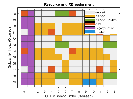
Plot Resource Element Assignments
The subframe resource grid is plotted to indicate the locations of the EPDCCH, EPDCCH DMRS, CRS and CSI-RS. If chs.EPDCCHStart>0, the location of the legacy control region is also shown.
Reference
1. TS 36.101,211,212
2. MathWorks