HC-SR04基本工作原理:
(1)采用IO口TRIG触发测距,给最少10us的高电平信呈。
(2)模块自动发送8个40khz的方波,自动检测是否有信号返回;
(3)有信号返回, 通过IO口ECHO输出一个高电平, 高电平持续的时间就是超声波从发射到返回的时间。
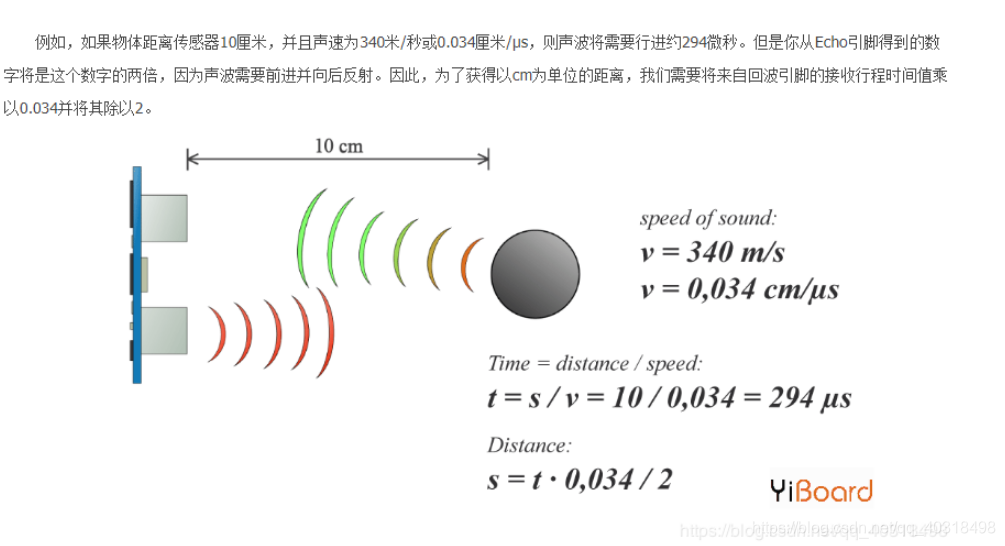
测试距离=(高电平时间*声速(340M/S))/2。

程序编写思路是:
1、配置好使用到的GPIO以及定时器;
2、给模块TRIG端口发送大于10us的高电平信号,当收、收到ECHO回响信号是,打开定时器开始定时;
3、当回响信号消失,关闭定时器;
4、通过定时器定时时间来确定距离。
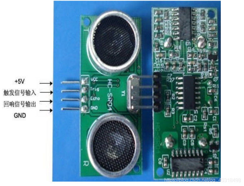
连线
1.这里,HC-SR04模块必须使用5V供电,不能是3.3V (若接3.3V,则数据出错)
2.Trig引脚我这里接GPIOB6
3.Echo引脚我这里接GPIOB7
相关代码
main.c
#include "led.h"
#include "delay.h"
#include "key.h"
#include "sys.h"
#include "usart.h"
#include "timer.h"

int main(void)
{
	u32 count = 0;
	float Distance = 0;
	delay_init();	    	 //延时函数初始化
	NVIC_PriorityGroupConfig(NVIC_PriorityGroup_2); //设置NVIC中断分组2:2位抢占优先级,2位响应优先级
	uart_init(115200);	 //串口初始化为115200
	LED_Init();			     //LED端口初始化
	Ultrasonic_Config();	//引脚初始化
	Timer2_Config();	//定时器2初始化
	GPIO_SetBits(GPIOB,GPIO_Pin_5);	//一开始我给它亮
	LED0 = 0;	//小灯指示用途
	LED1 = 0;
	printf("Test start\n");
	while(1)
	{
		//拉高Trig引脚10us
		GPIO_ResetBits(GPIOB, GPIO_Pin_6);//预先拉低Trig引脚
		GPIO_SetBits(GPIOB, GPIO_Pin_6);
		delay_us(10);
		GPIO_ResetBits(GPIOB, GPIO_Pin_6);//发出10us的脉冲
		TIM2->CNT = 0;	//计数器的值为0
		while(GPIO_ReadInputDataBit(GPIOB, GPIO_Pin_7) == 0);	//等待高电平
		TIM_Cmd(TIM2, ENABLE);	//开启定时器
		while(GPIO_ReadInputDataBit(GPIOB, GPIO_Pin_7) == 1){}	//等待低电平
		TIM_Cmd(TIM2, DISABLE);	//关闭定时器
		count = TIM2->CNT;	//获取定时器的值
		printf("count = %d\r\n",count);
		//count是计数器,单位是us,可根据上图转换一下即可。
		Distance = Distance_Calculate(count);	//计算距离
		printf("Distance = %f.", Distance);
		delay_ms(500);
		LED0 = !LED0;
		LED1 = !LED1;
	}
}
led.h
#ifndef __LED_H
#define __LED_H
#include "sys.h"

#define LED0 PBout(5)// PB5
#define LED1 PEout(5)// PE5

void LED_Init(void);//初始化
float Distance_Calculate(u16 count);
void Timer2_Config(void);
void Ultrasonic_Config(void);
led.c
void LED_Init(void)
{
	GPIO_InitTypeDef  GPIO_InitStructure;

	RCC_APB2PeriphClockCmd(RCC_APB2Periph_GPIOB|RCC_APB2Periph_GPIOE, ENABLE);	 //使能PB,PE端口时钟

	GPIO_InitStructure.GPIO_Pin = GPIO_Pin_5;				 //LED0-->PB.5 端口配置
	GPIO_InitStructure.GPIO_Mode = GPIO_Mode_Out_PP; 		 //推挽输出
	GPIO_InitStructure.GPIO_Speed = GPIO_Speed_50MHz;		 //IO口速度为50MHz
	GPIO_Init(GPIOB, &GPIO_InitStructure);					 //根据设定参数初始化GPIOB.5
	GPIO_SetBits(GPIOB,GPIO_Pin_5);						 //PB.5 输出高

	GPIO_InitStructure.GPIO_Pin = GPIO_Pin_5;	    		 //LED1-->PE.5 端口配置, 推挽输出
	GPIO_Init(GPIOE, &GPIO_InitStructure);	  				 //推挽输出 ,IO口速度为50MHz
	GPIO_SetBits(GPIOE,GPIO_Pin_5); 						 //PE.5 输出高
}
void Ultrasonic_Config(void){
	GPIO_InitTypeDef GPIO_InitStructure;
	RCC_APB2PeriphClockCmd(RCC_APB2Periph_GPIOB,ENABLE);
	GPIO_InitStructure.GPIO_Pin = GPIO_Pin_6;	//Trig
	//GPIO_InitStructure.GPIO_Mode = GPIO_Mode_AF_PP;
	GPIO_InitStructure.GPIO_Mode = GPIO_Mode_Out_PP;	//复用推挽输出
	GPIO_InitStructure.GPIO_Speed = GPIO_Speed_50MHz;
	GPIO_Init(GPIOB,&GPIO_InitStructure);

	GPIO_InitStructure.GPIO_Pin = GPIO_Pin_7;	//ECHO,输入
	GPIO_InitStructure.GPIO_Mode = GPIO_Mode_IN_FLOATING;
	//GPIO_InitStructure.GPIO_Mode = GPIO_Mode_IPD;	//设为输入
	GPIO_Init(GPIOB,&GPIO_InitStructure);
}
void Timer2_Config(void){
	TIM_TimeBaseInitTypeDef TIM_TimeBaseInitStructure;
	RCC_APB1PeriphClockCmd(RCC_APB1Periph_TIM2,ENABLE);
	TIM_TimeBaseInitStructure.TIM_Prescaler = 71;
	TIM_TimeBaseInitStructure.TIM_Period = 49999;	//72*50000/72 = 50000us = 500ms.
	TIM_TimeBaseInitStructure.TIM_CounterMode = TIM_CounterMode_Up;
	TIM_TimeBaseInitStructure.TIM_ClockDivision = TIM_CKD_DIV1;
	TIM_TimeBaseInit(TIM2,&TIM_TimeBaseInitStructure);
	TIM_ClearFlag(TIM2,TIM_FLAG_Update);	//更新产生中断
}
usart.c
void uart_init(u32 bound){
	  //GPIO端口设置
	GPIO_InitTypeDef GPIO_InitStructure;
	USART_InitTypeDef USART_InitStructure;
	NVIC_InitTypeDef NVIC_InitStructure;

	RCC_APB2PeriphClockCmd(RCC_APB2Periph_USART1|RCC_APB2Periph_GPIOA, ENABLE);	//使能USART1,GPIOA时钟

	//USART1_TX   GPIOA.9
	GPIO_InitStructure.GPIO_Pin = GPIO_Pin_9; //PA.9
	GPIO_InitStructure.GPIO_Speed = GPIO_Speed_50MHz;
	GPIO_InitStructure.GPIO_Mode = GPIO_Mode_AF_PP;	//复用推挽输出
	GPIO_Init(GPIOA, &GPIO_InitStructure);//初始化GPIOA.9

	//USART1_RX	  GPIOA.10初始化
	GPIO_InitStructure.GPIO_Pin = GPIO_Pin_10;//PA10
	GPIO_InitStructure.GPIO_Mode = GPIO_Mode_IN_FLOATING;//浮空输入
	GPIO_Init(GPIOA, &GPIO_InitStructure);//初始化GPIOA.10

	//Usart1 NVIC 配置
	NVIC_InitStructure.NVIC_IRQChannel = USART1_IRQn;
	NVIC_InitStructure.NVIC_IRQChannelPreemptionPriority=3 ;//抢占优先级3
	NVIC_InitStructure.NVIC_IRQChannelSubPriority = 3;		//子优先级3
	NVIC_InitStructure.NVIC_IRQChannelCmd = ENABLE;			//IRQ通道使能
	NVIC_Init(&NVIC_InitStructure);	//根据指定的参数初始化VIC寄存器

	//USART 初始化设置

	USART_InitStructure.USART_BaudRate = bound;//串口波特率
	USART_InitStructure.USART_WordLength = USART_WordLength_8b;//字长为8位数据格式
	USART_InitStructure.USART_StopBits = USART_StopBits_1;//一个停止位
	USART_InitStructure.USART_Parity = USART_Parity_No;//无奇偶校验位
	USART_InitStructure.USART_HardwareFlowControl = USART_HardwareFlowControl_None;//无硬件数据流控制
	USART_InitStructure.USART_Mode = USART_Mode_Rx | USART_Mode_Tx;	//收发模式

	USART_Init(USART1, &USART_InitStructure); //初始化串口1
	USART_ITConfig(USART1, USART_IT_RXNE, ENABLE);//开启串口接受中断
	USART_Cmd(USART1, ENABLE);                    //使能串口1
}
实验结果
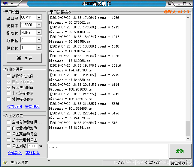
说明:count是计数器
几个简单的问题
由于学着后边的知识,前面逐渐忘掉一点,这里回顾一下定时时间跟cnt的关系。
如
	TIM_TimeBaseInitStructure.TIM_Prescaler = 71;
	TIM_TimeBaseInitStructure.TIM_Period = 49999;	//72*50000/72 = 50000us = 500ms.
计数频率为:72000000/72 = 1MHZ
计数时间到50000也就是计数的时间是50000/1M = 0.05s = 50ms。
当 APB1 的时钟分频数为 1 的 时候,TIM2~7 的时钟为 APB1 的时钟,而如果 APB1 的时钟分频数不为 1,那么 TIM2~7 的时 钟频率将为 APB1 时钟的两倍。因此,TIM3 的时钟为 72M,再根据我们设计的 arr 和 psc 的值, 就可以计算中断时间了。
计算公式如下:
Tout= ((arr+1)*(psc+1))/Tclk;
Tclk:TIM3 的输入时钟频率(单位为 Mhz)。
Tout:TIM3 溢出时间(单位为 us)。
根据公式,这里的定时时间为:Tout= ((71+1)*(49999+1))/72=50000us=50ms,其实应该也就是单位换算问题。
本文,计数器从0开始,最大是65535,也就是从0最大能计数到49999,不产生溢出。
由于HC-SR04最大能测量4m的距离,按S = 4m处理:

v = 340m/s,v = 0.034cm/us.
t = s/v = 400cm/0.034cm/us = 11764us
而我设置计数50000次,也就是50000us,因此,是能够测量最大距离的。
参考资料
[1] STM32F103 实验定时器 https://blog.csdn.net/qq_40318498/article/details/96436994
[2] STM32F103 实验按键输入与串口实验 https://blog.csdn.net/qq_40318498/article/details/95959478
[3] 基于STM32使用超声波HC-SR04模块 https://blog.csdn.net/Aphea/article/details/77447428