STM32 RS232 communication
Article directory
1. Overview of RS232 features
RS-232 is a serial communication interface, an asynchronous transmission standard interface established by the Electronic Industries Association (EIA). Released in 1962, named EIA-232-E, as an industrial standard to ensure compatibility between products from different manufacturers. RS is the abbreviation of "Recommended Standard" in English, and 232 is the identification number. RS232 is full-duplex communication, and the communication distance is up to 15 meters.
In the past, computers mostly used the RS-232 interface standard, which is a 25-pin DB-25 connector. Now it is more popular to use 9 A DB-9 connector. But gradually I found that it is more popular to use USB instead, which saves more space. The RS-232 interface in industrial control generally uses only three lines: TXD, RXD and GND to achieve data transmission.
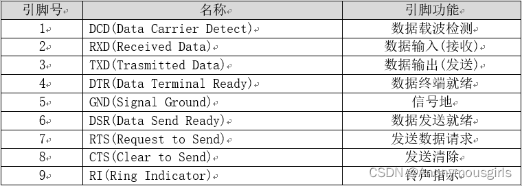
1.1 DB9 pin definition
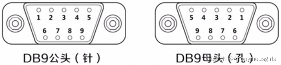
DB9 pin definition and function comparison table:
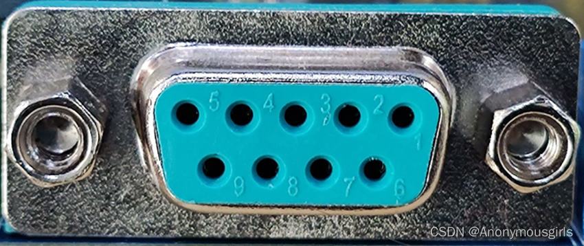
Physical map:

1.2 Electrical characteristics
Comparison between RS-232 level and COMS/TTL level:
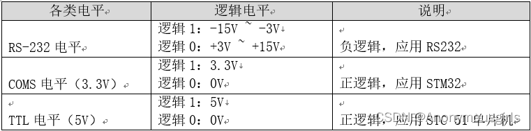
It should be noted that the signals between them cannot communicate directly. 232 uses negative logic and the logic voltage is also different. .
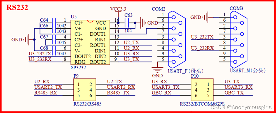
2. Communication schematic diagram
3. Communication protocol
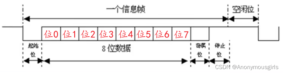
Data frame format:
Start bit: occupies 1 bit, specified as logic 0 level.
Valid data bits: optional 5, 6, 7, 8, or 9 bits, LSB first (least significant bit), MSB last (most significant bit), that is, bits 0 to 7, Transmit valid information.
Check digit: Optional 1 digit, or no digit.
Stop bit: required, optional 0.5, 1, 1.5, 2 bits, specified as logic 1 level.
4. Core code
The main code is as follows:
Note: This routine is directly modified from the serial port routine, directly changing serial port 1 to serial port 2, and deleting the system part. So the function is the same as the experimental effect of serial port 1.
uart.c
#pragma import(__use_no_semihosting)
//标准库需要的支持函数
struct __FILE
{


	int handle;
};

FILE __stdout;
//定义_sys_exit()以避免使用半主机模式
void _sys_exit(int x)
{


	x = x;
}
//重定义fputc函数
int fputc(int ch, FILE *f)
{


	while((USART2->SR&0X40)==0);//循环发送,直到发送完毕
    USART2->DR = (u8) ch;
	return ch;
}
u8 USART_RX_BUF[USART_REC_LEN];     //接收缓冲,最大USART_REC_LEN个字节.
//接收状态
//bit15,	接收完成标志
//bit14,	接收到0x0d
//bit13~0,	接收到的有效字节数目
u16 USART_RX_STA=0;       //接收状态标记

void uart2_Init(u32 baudrate)
{


    GPIO_InitTypeDef GPIO_InitStructure;
    USART_InitTypeDef USART_InitStructure;
    NVIC_InitTypeDef NVIC_InitStructure;

    RCC_APB1PeriphClockCmd(RCC_APB1Periph_USART2, ENABLE);
    RCC_APB2PeriphClockCmd(RCC_APB2Periph_GPIOA, ENABLE);//使能USART2,GPIOA时钟

    GPIO_InitStructure.GPIO_Pin = GPIO_Pin_2;//PA.2
    GPIO_InitStructure.GPIO_Speed = GPIO_Speed_50MHz;
    GPIO_InitStructure.GPIO_Mode = GPIO_Mode_AF_PP;//复用推挽输出
    GPIO_Init(GPIOA, &GPIO_InitStructure);//初始化GPIOA.2

    GPIO_InitStructure.GPIO_Pin = GPIO_Pin_3;//PA3
    GPIO_InitStructure.GPIO_Mode = GPIO_Mode_IN_FLOATING;//浮空输入
    GPIO_Init(GPIOA, &GPIO_InitStructure);//初始化GPIOA.3

    //USART 初始化设置
    USART_InitStructure.USART_BaudRate = baudrate;//串口波特率
    USART_InitStructure.USART_WordLength = USART_WordLength_8b;//字长为8位数据格式
    USART_InitStructure.USART_StopBits = USART_StopBits_1;//一个停止位
    USART_InitStructure.USART_Parity = USART_Parity_No;//无奇偶校验位
    USART_InitStructure.USART_HardwareFlowControl = USART_HardwareFlowControl_None;//无硬件数据流控制
    USART_InitStructure.USART_Mode = USART_Mode_Rx | USART_Mode_Tx;//收发模式

    USART_Init(USART2, &USART_InitStructure); //初始化串口2
    USART_Cmd(USART2, ENABLE);                    //使能串口2
}

void USART2_IRQHandler(void)                	//串口2中断服务程序
{


	u8 Res;
	if(USART_GetITStatus(USART2, USART_IT_RXNE) != RESET)  //接收中断(接收到的数据必须是0x0d 0x0a结尾)
		{


		Res =USART_ReceiveData(USART2);	//读取接收到的数据

		if((USART_RX_STA&0x8000)==0)//接收未完成
			{


			if(USART_RX_STA&0x4000)//接收到了0x0d
				{


				if(Res!=0x0a)USART_RX_STA=0;//接收错误,重新开始
				else USART_RX_STA|=0x8000;	//接收完成了
				}
			else //还没收到0X0D
				{


				if(Res==0x0d)USART_RX_STA|=0x4000;
				else
					{


					USART_RX_BUF[USART_RX_STA&0X3FFF]=Res ;
					USART_RX_STA++;
					if(USART_RX_STA>(USART_REC_LEN-1))USART_RX_STA=0;//接收数据错误,重新开始接收
					}
				}
			}
     }
}
uart.h

#define USART_REC_LEN  			200  	//定义最大接收字节数 200
extern u8  USART_RX_BUF[USART_REC_LEN]; //接收缓冲,最大USART_REC_LEN个字节.末字节为换行符
extern u16 USART_RX_STA;         		//接收状态标记
//如果想串口中断接收,请不要注释以下宏定义
void uart_init(u32 bound);
main.c

 int main(void)
 {


 	u16 t;
	u16 len;
	u16 times=0;
	delay_init();	    	 //延时函数初始化
	NVIC_PriorityGroupConfig(NVIC_PriorityGroup_2); //设置NVIC中断分组2:2位抢占优先级,2位响应优先级
	uart_init(115200);	 //串口初始化为115200
 	LED_Init();			     //LED端口初始化
	KEY_Init();          //初始化与按键连接的硬件接口
 	while(1)
	{


		if(USART_RX_STA&0x8000)
		{


			len=USART_RX_STA&0x3fff;//得到此次接收到的数据长度
			printf("\r\n您发送的消息为:\r\n\r\n");
			for(t=0;t<len;t++)
			{


				USART_SendData(USART2, USART_RX_BUF[t]);//向串口2发送数据
				while(USART_GetFlagStatus(USART2,USART_FLAG_TC)!=SET);//等待发送结束
			}
			printf("\r\n\r\n");//插入换行
			USART_RX_STA=0;
		}else
		{


			times++;
			if(times%5000==0)
			{


				printf("\r\n战舰STM32开发板 串口实验\r\n");
				printf("正点原子@ALIENTEK\r\n\r\n");
			}
			if(times%200==0)printf("请输入数据,以回车键结束\n");
			if(times%30==0)LED1=!LED1;//闪烁LED,提示系统正在运行.
			delay_ms(10);
		}
	}
 }
Here, RS232 is connected to serial port 2, so just initialize serial port 2. If you need to use interrupts, you need to write an interrupt processing function and a serial port redirection function to print information.
5. Summary
Using RS232 is actually using usart. The principle is the same. You need to add a level conversion chip to communicate with both.