Introduction to USART
USART (Universal Synchronous/Asynchronous Receiver/Transmitter) universal synchronous/asynchronous receiver/transmitter (UART is an asynchronous receiver/transmitter)
USART is an integrated hardware peripheral inside STM32. It can automatically generate data frame timing based on one byte of data in the data register and send it out from the TX pin. It can also automatically receive the data frame timing of the RX pin and splice it into one byte of data. , stored in the data register
Comes with a baud rate generator (equivalent to a frequency divider), up to 4.5Mbits/s
Configurable data bit length (8/9), stop bit length (0.5/1/1.5/2)
Optional parity bit (no parity/odd parity/even parity)
Supports synchronous mode, hardware flow control (tells the other party if it is ready to work), DMA, smart cards, IrDA, LIN
STM32F103C8T6 USART resources: USART1, USART2, USART3. For specific IO pins, see the GPIO definition diagram.
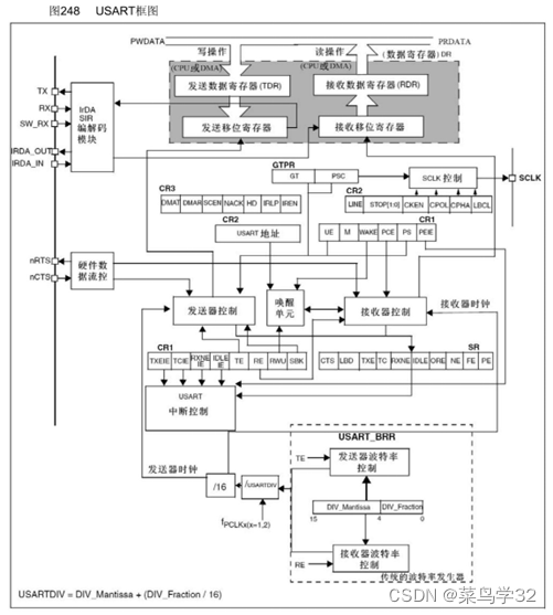
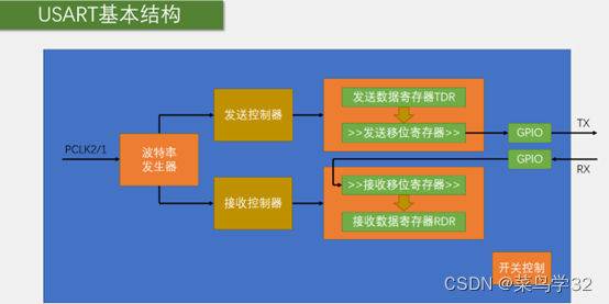
The transmitter controls the transmit shift register. When data enters the transmit data register, the data will be transferred to the shift register, and the flag position will be set to 1 to tell whether the data can continue to be written. The receiving shift register is the same as the receiving data register.
SCLK only supports output and does not support input, so synchronous serial communication cannot be achieved between the two USARTs, but it is compatible with other protocols, such as SPI. Adaptive baud rate can also be done. The wake-up unit can realize communication with multiple devices, and the device will work when the corresponding address is sent.
During input, each bit will be sampled 16 times to ensure the accuracy of the data, and the noise flag NE will also be set to 1. See PPT107 for the specific schematic diagram.
The baud rate of the transmitter and receiver is determined by the DIV in the baud rate register BRR
Calculation formula: Baud rate = fPCLK2/1 / (16 * DIV)
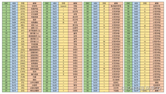
When displayed as text, the corresponding HEX will be converted to the corresponding characters
In USART, if you use bytes to transmit one by one, some errors will occur. In this case, several bytes can be encapsulated and sent. This is the data packet
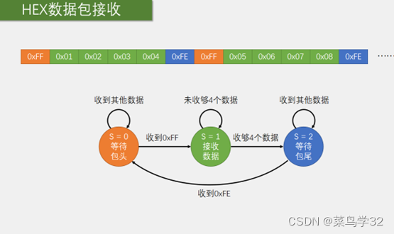

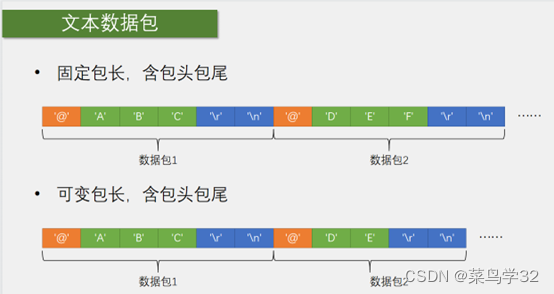
There are two types of data packets. The header and tail of the packet are equivalent to a flag. When a specific byte or character is received, the reception can be started or ended, for example, and then put into an array. The data packet reception uses the state machine method to receive. When the received byte is not the specified byte or the character is the packet header, it will wait until it is received. When it is received, it will set S=0 and enter the data collection... The flow chart can be seen above.
#ifndef __SERIAL_H
#define __SERIAL_H

 #include <stdio.h>
extern uint8_t Serial_TxPacket[];
extern char Serial_RxPacket[];
void Serial_Init(void);
void Serial_SendArry(uint8_t *Array,uint16_t Length);
void Serial_SendByte(uint8_t Byte);
void Serial_SendString(char*String);
void Serial_SendNumber(uint32_t Number,uint8_t Length);
void Serial_printf(char*format,...);
uint8_t Serial_chetByte();
uint8_t Serial_GetRxFlag(void);
uint8_t Serial_GetRxData(void);
void Serial_SendPacket(void);
#endif
#include "stm32f10x.h" // Device header
#include <stdio.h>
#include <stdarg.h>
uint8_t Serial_RxData;
uint8_t Serial_RxFlag;
uint8_t Serial_TxPacket[4];
char Serial_RxPacket[100];
void Serial_Init(void)
{
RCC_APB2PeriphClockCmd(RCC_APB2Periph_USART1,ENABLE);
RCC_APB2PeriphClockCmd(RCC_APB2Periph_GPIOA,ENABLE);
GPIO_InitTypeDef GPIO_InitStructure;
GPIO_InitStructure.GPIO_Mode = GPIO_Mode_AF_PP;//这里数据手册上PA9可以直接用USART1
GPIO_InitStructure.GPIO_Speed = GPIO_Speed_50MHz;
GPIO_InitStructure.GPIO_Pin = GPIO_Pin_9;
GPIO_Init(GPIOA, &GPIO_InitStructure);
GPIO_InitStructure.GPIO_Mode = GPIO_Mode_IPU;//这里数据手册上PA9可以直接用USART1
GPIO_InitStructure.GPIO_Speed = GPIO_Speed_50MHz;
GPIO_InitStructure.GPIO_Pin = GPIO_Pin_10;
GPIO_Init(GPIOA, &GPIO_InitStructure);
USART_InitTypeDef USART_InitStructure;
USART_InitStructure.USART_BaudRate=9600;//波特率,这里注意波特率要和连接设备的波特率一样
USART_InitStructure.USART_HardwareFlowControl=USART_HardwareFlowControl_None;//流控,这里不选择
USART_InitStructure.USART_Mode=USART_Mode_Tx|USART_Mode_Rx;//接收和发送功能
USART_InitStructure.USART_Parity=USART_Parity_No;//校验选择
USART_InitStructure.USART_StopBits=USART_StopBits_1;//停止位
USART_InitStructure.USART_WordLength=USART_WordLength_8b;//字长选择
USART_Init(USART1,&USART_InitStructure);
USART_ITConfig(USART1,USART_IT_RXNE,ENABLE);//开启标志位到NVIC的输出
NVIC_PriorityGroupConfig(NVIC_PriorityGroup_2);
NVIC_InitTypeDef NVIC_InitStructure;
NVIC_InitStructure.NVIC_IRQChannel=USART1_IRQn;
NVIC_InitStructure.NVIC_IRQChannelCmd=ENABLE;
NVIC_InitStructure.NVIC_IRQChannelPreemptionPriority=1;
NVIC_InitStructure.NVIC_IRQChannelSubPriority=1;
NVIC_Init(&NVIC_InitStructure);
USART_Cmd(USART1,ENABLE);
}
void Serial_SendByte(uint8_t Byte)//发送
{
USART_SendData(USART1,Byte);
while(USART_GetFlagStatus(USART1,USART_FLAG_TXE)==RESET);//等待一下查看标志位是否置1,以免覆盖原来的数据
}
uint8_t Serial_chetByte()//直接读取寄存器的值,但会一直占用软件资源
{
while(USART_GetFlagStatus(USART1,USART_FLAG_RXNE)==RESET);
Serial_RxData=USART_ReceiveData(USART1);
return Serial_RxData;
}
void Serial_SendArry(uint8_t *Array,uint16_t Length)
{
uint16_t i;
for(i=0;i<Length;i++)
{
Serial_SendByte(Array[i]);
}
}
void Serial_SendString(char*String)
{
uint8_t i;
for(i=0;String[i]!='\0';i++)
{
Serial_SendByte(String[i]);
}
}
uint32_t Serial_Pow(uint32_t X,uint32_t Y)
{
uint32_t Result=1;
while(Y--)
{
Result*=X; //相当于X的Y次方
}
return Result;
}
void Serial_SendNumber(uint32_t Number,uint8_t Length)
{
uint8_t i;
for(i=0;i<Length;i++)
{
Serial_SendByte(Number/Serial_Pow(10,Length-i-1)%10+0x30);
}
}
int fputc(int ch,FILE*f)//printf
{
Serial_SendByte(ch);
return ch;
}
void Serial_printf(char*format,...)
{
char String[100];
va_list arg;
va_start(arg,format);
vsprintf(String,format,arg);
va_end(arg);
Serial_SendString(String);
}
uint8_t Serial_GetRxFlag(void)
{
if(Serial_RxFlag==1)
{
Serial_RxFlag=0;
return 1;
}
return 0;
}
uint8_t Serial_GetRxData(void)
{
return Serial_RxData;
}
void Serial_SendPacket(void)//发送数据包函数
{
Serial_SendByte(0xFF);
Serial_SendArry(Serial_TxPacket,4);
Serial_SendByte(0xFE);
}
void USART1_IRQHandler(void)//中断函数
{
static uint8_t RxState=0;
static uint8_t pRxPacket=0;//用来指示数组位置
if(USART_GetITStatus(USART1,USART_IT_RXNE)==SET)
{
Serial_RxData=USART_ReceiveData(USART1);
if(RxState==0)
{
if(Serial_RxData=='@')
{
RxState=1;
pRxPacket=0;
}
}
else if(RxState==1)
{
if(Serial_RxData=='\r')
{
RxState=2;
}
else
{
Serial_RxPacket[pRxPacket]=Serial_RxData;
pRxPacket++;
}
}
else if(RxState==2)
{
if(Serial_RxData=='\n')
{
RxState=0;
Serial_RxPacket[pRxPacket]='\0';
Serial_RxFlag=1;
}
}
USART_ClearITPendingBit(USART1,USART_IT_RXNE);
}
}
Use the Serial_printf function to output, for example, Serial_printf("Num=%d\r\n",666);stm32 will send 666 data from TX to the connected device. USART_ReceiveData(USART1); This function is used by stm32 to receive data. The above code has a protocol and requires @[]/r/n. The protocol means that the complete format can be truly received, such as @2/ r/n, only 2 is the data you really want, the others are protocol formats, not necessarily these characters, you can define them yourself. The main purpose of the protocol is to prevent errors and ensure the rigor of the program.
If you want no protocol, just change the interrupt function to the following
//无协议

void USART1_IRQHandler(void)//中断函数
{


	if(USART_GetITStatus(USART1,USART_IT_RXNE)==SET)
	{
			Serial_RxData=USART_ReceiveData(USART1);

	}
}
This article was studied with Jiangsu University of Science and Technology and is my study notes. If there is any infringement, please contact me to delete it!