1. Background knowledge of communication interface
Ways of communication between devices
1. In general, the communication methods between devices can be divided into parallel communication and serial communication . Their difference is:
Serial communication : Data is transmitted in bit order. Advantages: occupies less pin resources, disadvantages: relatively slow speed.
Parallel communication : All bits of data are transmitted at the same time. Advantages: fast speed, disadvantages: occupies a lot of pin resources.
Serial communication generally transmits data in a frame format, that is, one frame at a time. Each frame contains start signal, data information, stop information, and possibly check information.
2. Classification of serial communication
(1) According to the data transmission direction, it is divided into:
Simplex : data transmission only supports data transmission in one direction;
half-duplex : allows data transmission in two directions. However, at a certain moment, data is only allowed to be transmitted in one direction. It is actually a simplex communication that switches directions; it does not require independent receiving and sending ends, and the two can be combined to use one port.
Full duplex : allows data to be transmitted in both directions at the same time. Therefore, full-duplex communication is a combination of two simplex communication methods, requiring independent receivers and transmitters.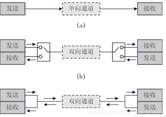
(2) According to the communication method, it is divided into:
Synchronous communication : with clock synchronization signal transmission. For example: SPI, IIC communication interface.
Asynchronous communication : without clock synchronization signal. For example: UART (Universal Asynchronous Receiver Transmitter), single bus.
In synchronous communication, a signal line is used to transmit signals above the transceiver device, and the two parties coordinate and synchronize data under the drive of the clock signal. For example, in communication, usually both parties will uniformly stipulate that the data line is sampled on the rising or falling edge of the clock signal.
In asynchronous communication, the clock signal is not used for data synchronization. They directly insert some signal bits for synchronization in the data signal, or pack the subject data, and transmit the data in the format of a data frame. In communication, it is also necessary for both parties to agree on the data transmission rate (that is, baud rate), etc., in order to better synchronize. Commonly used baud rates are 4800bps, 9600bps, 115200bps, etc.
In synchronous communication, most of the content transmitted by the data signal is valid data, and asynchronous communication will contain various identifiers of the data frame, so the efficiency of synchronous communication is high, but the allowable error of the clocks of both sides of synchronous communication is small. A slight clock error may lead to data disorder, and the allowable error of the clocks on both sides of asynchronous communication is relatively large.
Common serial communication interface: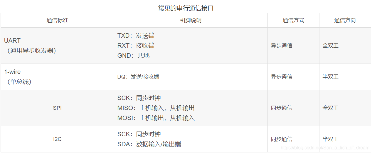
2. Universal Synchronous/Asynchronous Transceiver (USART)
1. The universal synchronous asynchronous transceiver is a serial communication device that can flexibly exchange full-duplex data with external devices. Unlike the USART, there is also a UART, which cuts out the synchronous communication function on the basis of the USART, and only has asynchronous communication. The simple distinction between synchronous and asynchronous is to look at the need for external clock output during communication. The serial communication we usually use is basically UART.
USART supports synchronous one-way communication and half-duplex single-wire communication; it also supports local interconnection network LIN, smart card (SmartCard) protocol and lrDA (Infrared Data Association) SIR ENDEC specification.
USART supports the use of DMA, which can realize high-speed data communication.
2. STM32 UART features
Full duplex asynchronous communication;
fractional baud rate generator system, providing accurate baud rate . Sending and receiving shared programmable baud rate, up to 4.5Mbits/s;
programmable data word length (8 or 9 bits);
configurable stop bit (support 1 or 2 stop bits);
configurable The use of DMA multi-buffer communication;
separate transmitter and receiver enable bits;
detection flags: ① receiving buffer ② sending buffer empty ③ transmission end flag;
multiple interrupt sources with flags, trigger interrupt;
other: calibration Inspection control, four error detection signs.
3. UART pin connection method
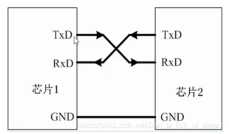
- RXD: data input pin, data receiving;
- TXD: Data transmission pin, data transmission.
For the connection between the two chips, the GND of the two chips share the same ground, and the TXD and RXD are cross-connected. The cross connection here means that the RxD of chip 1 is connected to the TXD of chip 2 and the RXD of chip 2 is connected to the TXD of chip 1. In this way, TTL level communication can be carried out between the two chips .
4. The detailed process of USART serial communication
UART (USART) block diagram

This block diagram is divided into three parts: upper, middle, and lower.
In the upper part of the block diagram, data enters the receive shift register from RX, then enters the receive data register, and is finally read by the CPU or DMA; the data is transferred from the CPU or DMA, enters the transmit data register, and then enters the transmit shift The register is finally sent out via TX.
However, the transmission and reception of UART need baud rate to control, how is the baud rate controlled?
This brings you to the lower part of the block diagram. There is an incoming arrow in both the receiving shift register and the sending shift register, which are respectively connected to the receiver control and the transmitter control. The two connected are the receiver clock and the transmitter clock. In other words, although asynchronous communication does not have a clock synchronization signal, it provides a clock signal for control within the serial port. What is the control of the receiver clock and the transmitter clock?
It can be seen that the receiver clock and transmitter clock are connected to the same control unit, which means that they share a baud rate generator.
Speaking of clocks, you must understand: UART1's clock is mounted on the APB2 bus, so the clock source is PCLK2 (high speed); while USART2~5 are mounted on APB1, so the clock source is PCLK1 .
In summary, serial peripherals are divided into data storage and transfer part , transceiver control part , and baud rate control part .
Data storage and transfer part : (1) When data needs to be sent, after the kernel or DMA peripheral writes the data from the memory into the sending data register TDR, the data will be automatically loaded into the sending shift register (this process generates TDR empty time TXE) Finally, it is sent out one by one through the serial port line TX (data transmission complete event TC is generated after all transmissions). The generated event will affect the value of the status register.
(2) When receiving data, it is a reverse process. The data is input from the serial port line RX to the receiving data shift register, and then automatically transferred to the receiving data register RDR, and finally read into the memory with a kernel command or DMA.
Transceiving control part : control sending and receiving by rewriting the control parameters of three USART control registers (CR1, CR2, CR3) and a status register (SR), such as parity bit, stop bit, etc., including interrupt to USART control.
Baud rate control part : The baud rate can be changed by controlling the clock, and the baud rate is the number of binary symbols transmitted per second, that is, it represents the data transmission rate. To configure the baud rate is actually to modify the parameter USARTDIV (the frequency division value of the serial port clock) in the baud rate register USART_BRR.
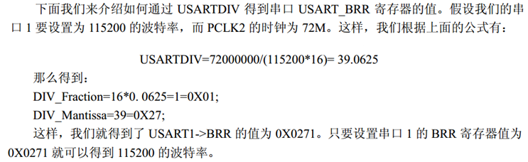
5. Calculation of baud rate
Speaking of baud rate, you must first understand the baud rate register
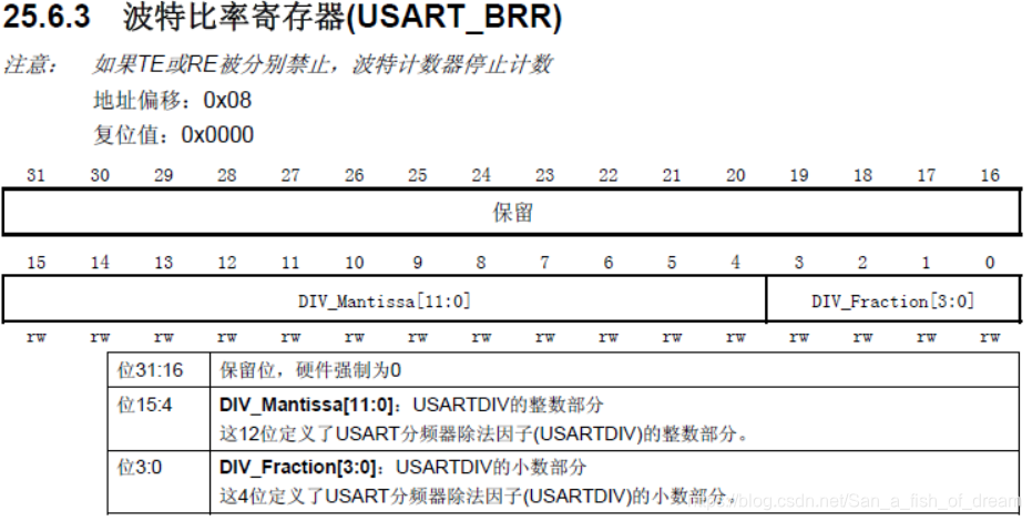
The formula for changing the baud rate by modifying the value of USARTDIV is as follows:

In the above formula, f PCLKx is the clock frequency of the serial port. As long as we get the value of USARTDIV, we can calculate the baud rate.
USARTDIV includes two parts in the definition of the baud rate register: DIV_Mantissa [15:4] (integer part) and DIV_Fraction [3:0] (decimal part).
The calculation formula is: USARTDIV = DIV_Mantis + (DIV_Fraction/16)
Note : When using the library function when configuring the serial port, you do not need to calculate the value of the register, just write it directly when setting the baud rate.
6, serial port operation related library functions
- 1 initialization function
void USART_Init(USART_TypeDef* USARTx, USART_InitTypeDef* USART_InitStruct);Function: Used for initialization of serial port baud rate, data word length, parity, hardware flow control, and transceiver enable.
- 2 enable functions
void USART_Cmd(USART_TypeDef* USARTx, FunctionalState NewState);
void USART_ITConfig(USART_TypeDef* USARTx, uint16_t USART_IT, FunctionalState NewState);
Function: The former enables the serial port, and the latter enables the related interrupts of the serial port.
- 2 data sending and receiving functions
void USART_SendData(USART_TypeDef* USARTx, uint16_t Data);
uint16_t USART_ReceiveData(USART_TypeDef* USARTx);
Function: The former sends data to the serial port, and the latter receives data from the serial port.
- 4 status bit functions
FlagStatus USART_GetFlagStatus(USART_TypeDef* USARTx, uint16_t USART_FLAG);
void USART_ClearFlag(USART_TypeDef* USARTx, uint16_t USART_FLAG);
ITStatus USART_GetITStatus(USART_TypeDef* USARTx, uint16_t USART_IT);
void USART_ClearITPendingBit(USART_TypeDef* USARTx, uint16_t USART_IT);
Function: The first two get (or clear) the status flag bit, and the latter two get (or clear) the interrupt status flag bit.
7. General steps for serial port operation
(1) Clock enable
Call function: RCC_APBxPeriphClockCmd(),
Including GPIO clock enable , serial port clock enable , if the pin is multiplexed, also enable the AFIO clock .
To be perfected
(2) Configure GPIO pins
Calling function: GPIO_Init()
USART peripheral pin multiplexing
When using USART, GPIO sometimes needs pin multiplexing (remapping), so how to judge whether remapping is required? Please refer to the related content of pin multiplexing configuration (to be added)
The following figure describes the pin settings of USART:
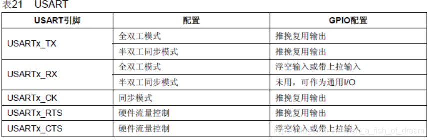
In the textbook, the initialization parameters of the multiplexed pin are: TX pin is multiplexed push-pull output, and the switching rate is 50MHZ; RX pin is floating input, and the switching rate is not set:
GPIO_InitStructure.GPIO_Pin = GPIO_Pin_9;    //TX引脚为PA9
GPIO_InitStructure.GPIO_Mode = GPIO_Mode_AF_PP;   //复用推挽输出
GPIO_InitStructure.GPIO_Speed = GPIO_Speed_50MHz;
GPIO_Init(USART1,&GPIO_InitStructure);

GPIO_InitStructure.GPIO_Pin = GPIO_Pin_10;   //RX引脚为P10
GPIO_InitStructure.GPIO_Mode = GPIO_Mode_IN_FLOATING;   //浮空输入
GPIO_Init(USART1,&GPIO_InitStructure);
(3) Configure the interrupt priority and enable the interrupt (this step is only necessary if you need to turn on the interrupt)
Calling function: NVIC_Init(); USART_ITConfig();
To be perfected
Note : If the relevant device needs to use the interrupt function, the interrupt priority must be configured before the device is enabled, and the interrupt of the device must be enabled.
(4) Initialize the serial port parameters and enable the serial device
Call function: USART_Cmd();
To be perfected
(5) Write interrupt handling function
Call function: USARTx_IRQHandler();
Serial data transmission and reception. Call function: USART_SendData(); USART_ReceiveData();
Get the serial port transmission status. Call function: USART_GetFlagStatus(); USART_ClearITPendingBit();
To be perfected
When writing an interrupt service function, the data of the relevant status bit is often obtained to determine whether an interrupt is generated. Therefore, it is necessary to have a certain understanding of the status register.
Status register (USART_SR)
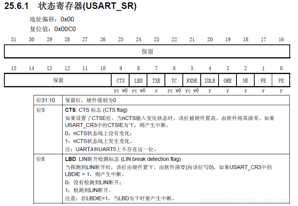
The status register is suitable for detecting the status of the serial port at this time. The states that it can detect include: sending register empty bits, sending complete bits, reading data register non-empty bits, detecting idle bits of the main line, overload error, and so on.
Here we mainly focus on two bits: RXNE and TC (the 5th and 6th digits).
RXNE (Read data register is not empty) : When this bit is set to 1, it means that data has been received and can be read out (that is, the data in the RDR shift register is transferred to the USART_DR register). What you need to do at this time is to read USART_DR as soon as possible to clear this bit, or you can write 0 to this bit to clear it directly.
TC (transmission complete) : When this bit is set to 1, it means that the data in USART_DR has been transmitted. If an interrupt with this bit is set, an interrupt will be generated. There are also two ways to clear this bit: read USART_SR and write USART_DR; write 0 directly to this bit.