The clock ip core is a commonly used IP core, which is mainly used for frequency multiplication, frequency division and phase adjustment of the input clock signal . In fact, it is relatively simple to implement these functions by yourself, but since vivado provides this packaged IP core, we can make full use of it and reduce the workload of developers, and the clock IP core also has some advanced cores. functions, such as dynamic adjustment of output clock frequency and phase, etc. This article mainly records the basic use of the clock ip core, with verilog and vhdl codes and corresponding testbench files for students to communicate and learn from each other.
1. Introduction to Clock IP
Before introducing clock management IP, you can first understand the concept of FPGA global clock resources. The global clock resource refers to the dedicated buffer and drive structure implemented by the full copper layer process in the FPGA to minimize the delay and jitter of the system clock reaching the basic logic units such as CLB, IOB, and BSRAM in the FPGA.
A global clock resource is a routing resource that is commonly used in designs. There are many forms of global clock resources, and various primitives of clock resources can be viewed through the language template of vivado.

The following is the process of using the ip core.
2. IP core settings in VIVADO
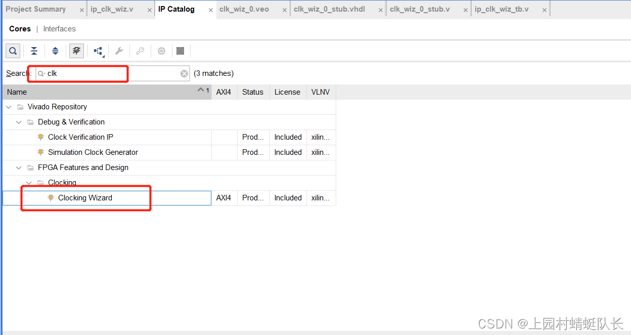
1. Select the clock ip core in the ip catalog. (left side)
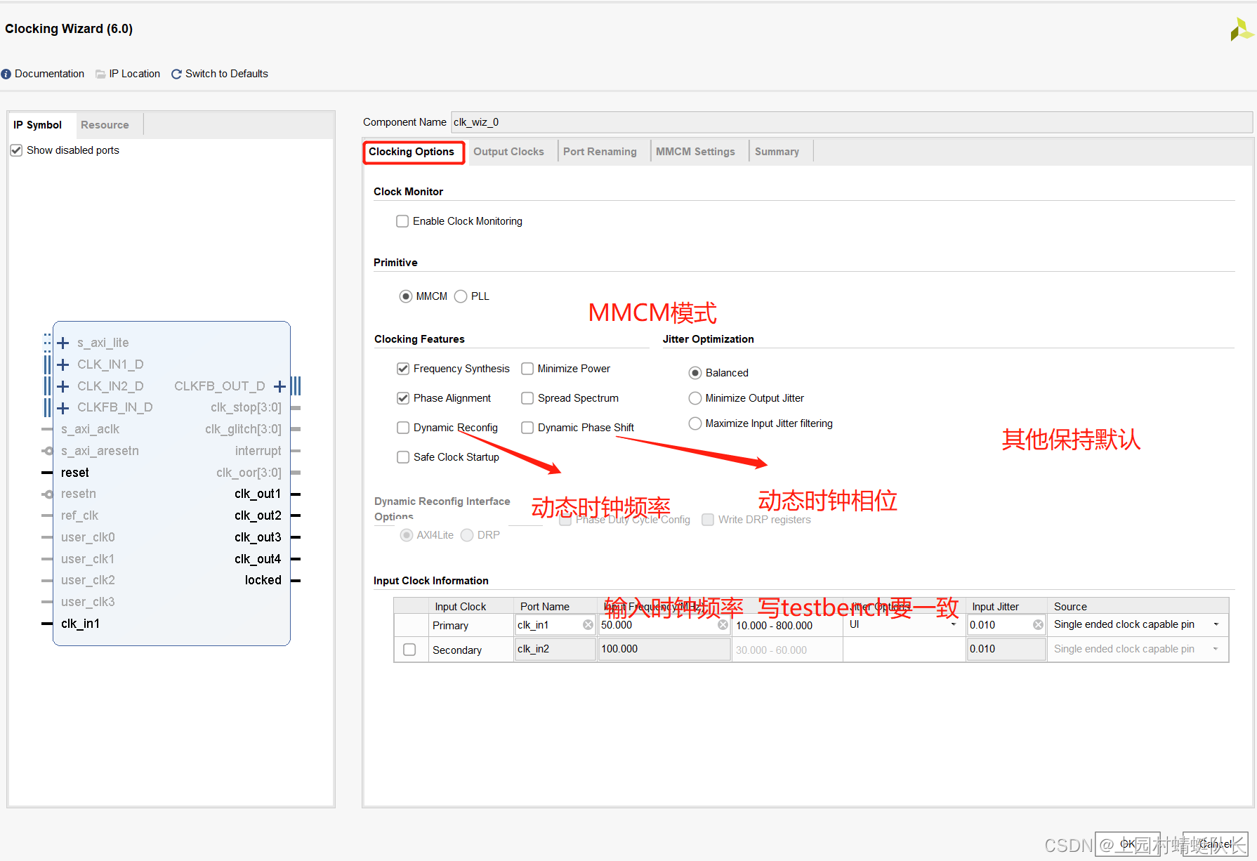
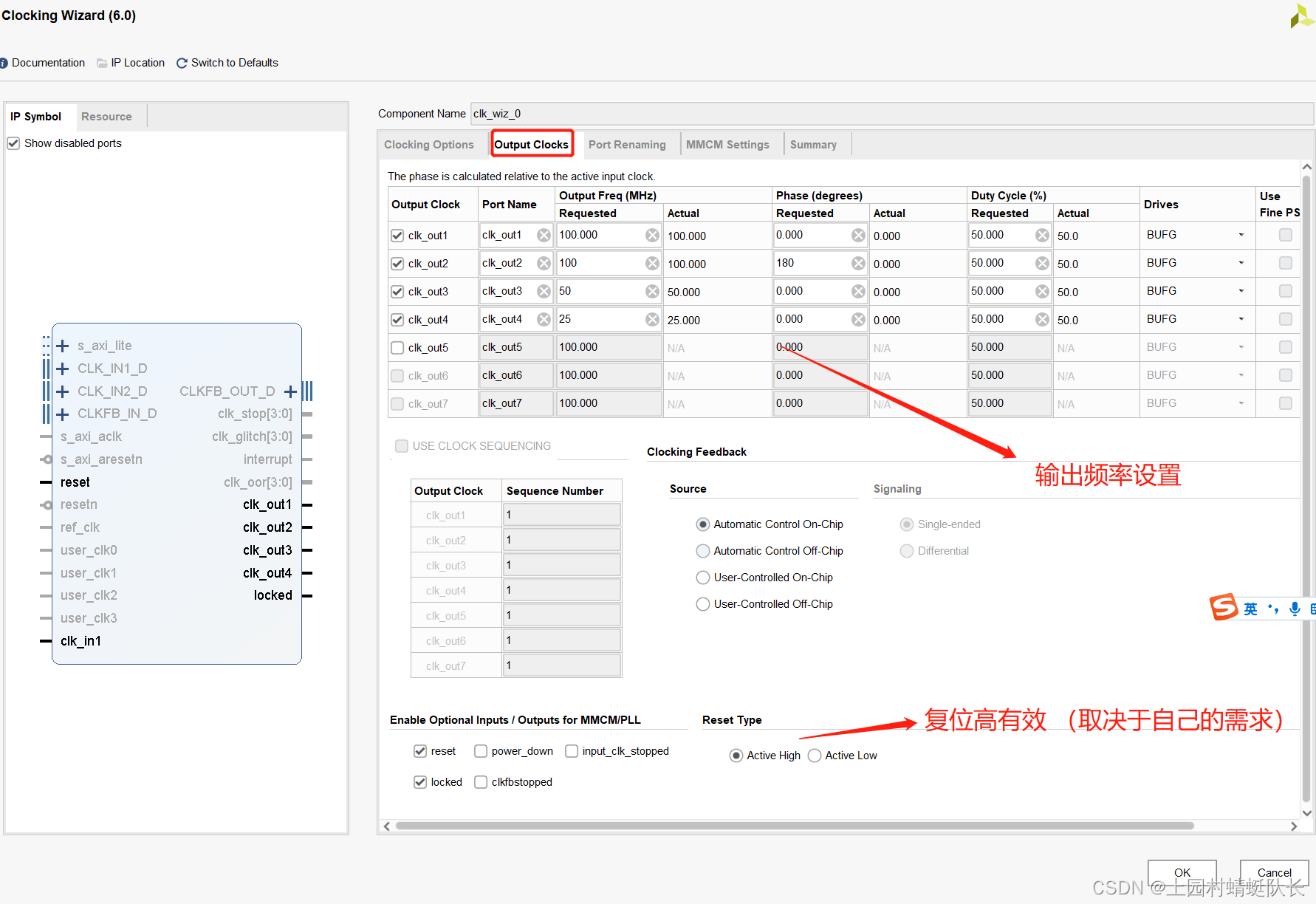
2. Set the ip core
3. Instantiate the template
Vivado provides instantiation templates, including verilog and vhdl versions. The instantiated template is obtained from ip_source.
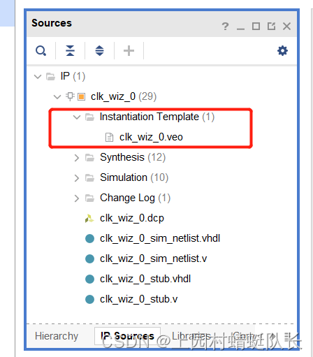
If it is verilog, click on the veo file to see the instantiated template.
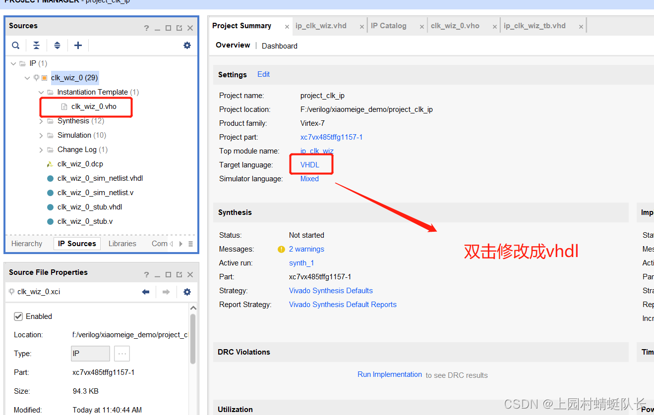
If it is VHDL, you need to check whether the target of the project is VHDL, so that the vhdl vho file can appear in the instantiated template.
Verilog instantiates ip core
  clk_wiz_0 instance_name
   (
    // Clock out ports
    .clk_out1(clk_out1),     // output clk_out1
    .clk_out2(clk_out2),     // output clk_out2
    .clk_out3(clk_out3),     // output clk_out3
    .clk_out4(clk_out4),     // output clk_out4
    // Status and control signals
    .reset(reset), // input reset
    .locked(locked),       // output locked
   // Clock in ports
    .clk_in1(clk_in1));      // input clk_in1
VHDL instantiates ip core
component clk_wiz_0
port
 (-- Clock in ports
  -- Clock out ports
  clk_out1          : out    std_logic;
  clk_out2          : out    std_logic;
  clk_out3          : out    std_logic;
  clk_out4          : out    std_logic;
  -- Status and control signals
  reset             : in     std_logic;
  locked            : out    std_logic;
  clk_in1           : in     std_logic
 );
end component;

-- COMP_TAG_END ------ End COMPONENT Declaration ------------
-- The following code must appear in the VHDL architecture
-- body. Substitute your own instance name and net names.
------------- Begin Cut here for INSTANTIATION Template ----- INST_TAG
your_instance_name : clk_wiz_0
   port map (
  -- Clock out ports
   clk_out1 => clk_out1,
   clk_out2 => clk_out2,
   clk_out3 => clk_out3,
   clk_out4 => clk_out4,
  -- Status and control signals
   reset => reset,
   locked => locked,
   -- Clock in ports
   clk_in1 => clk_in1
 );
4. Requirements Analysis and Code
Requirements introduction:
Input 50Mhz clock, generate 100M output, 100M output (180° phase), 50M, 25M.
verilog top-level file
After setting the IP core, the top-level file of the verilog project:
`timescale 1ns / 1ps


module ip_clk_wiz(
    input sys_clk,
    input sys_rst,
    output              clk_100m       ,  //100Mhz时钟频率
    output              clk_100m_180deg,  //100Mhz时钟频率,相位偏移180度
    output              clk_50m        ,  //50Mhz时钟频率
    output              clk_25m           //25Mhz时钟频率
    );
wire        locked;
  clk_wiz_0 clk_wiz_0
   (
    // Clock out ports
    .clk_out1(clk_100m),     // output clk_out1
    .clk_out2(clk_100m_180deg),     // output clk_out2
    .clk_out3(clk_50m),     // output clk_out3
    .clk_out4(clk_25m),     // output clk_out4
    // Status and control signals
    .reset(sys_rst), // input reset
    .locked(locked),       // output locked
   // Clock in ports
    .clk_in1(sys_clk));      // input clk_in1
endmodule
verilog testbench file
`timescale 1ns / 1ps

module ip_clk_wiz_tb(
    );

reg     sys_clk;
reg     sys_rst;

wire    clk_100m;
wire    clk_100m_180deg;
wire    clk_50m;
wire    clk_25m;


always #10 sys_clk = ~sys_clk;


initial begin
    sys_clk = 1'b0;
    sys_rst = 1'b1;
    #200//延时200
    sys_rst = 1'b0;
end

ip_clk_wiz u_ip_clk_wiz(
    .sys_clk          (sys_clk      ),
    .sys_rst          (sys_rst      ),

    .clk_100m         (clk_100m       ),
    .clk_100m_180deg  (clk_100m_180deg),
    .clk_50m          (clk_50m        ),
    .clk_25m          (clk_25m        )
    );

endmodule
VHDL top level file
library IEEE;
use IEEE.STD_LOGIC_1164.ALL;

-- Uncomment the following library declaration if using
-- arithmetic functions with Signed or Unsigned values
--use IEEE.NUMERIC_STD.ALL;

-- Uncomment the following library declaration if instantiating
-- any Xilinx leaf cells in this code.
--library UNISIM;
--use UNISIM.VComponents.all;

entity ip_clk_wiz is
  Port ( sys_clk: in std_logic;
         sys_rst: in std_logic;

         clk_100m: out std_logic;
         clk_100m_180: out std_logic;
         clk_25m: out std_logic;
         clk_50m: out std_logic
         );
end ip_clk_wiz;

architecture Behavioral of ip_clk_wiz is
signal locked :std_logic;
component clk_wiz_0
port
 (-- Clock in ports
  -- Clock out ports
  clk_out1          : out    std_logic;
  clk_out2          : out    std_logic;
  clk_out3          : out    std_logic;
  clk_out4          : out    std_logic;
  -- Status and control signals
  reset             : in     std_logic;
  locked            : out    std_logic;
  clk_in1           : in     std_logic
 );
end component;
begin
-- COMP_TAG_END ------ End COMPONENT Declaration ------------
-- The following code must appear in the VHDL architecture
-- body. Substitute your own instance name and net names.
------------- Begin Cut here for INSTANTIATION Template ----- INST_TAG
i_clk : clk_wiz_0
   port map (
  -- Clock out ports
   clk_out1 => clk_100m,
   clk_out2 => clk_100m_180,
   clk_out3 => clk_50m,
   clk_out4 => clk_25m,
  -- Status and control signals
   reset => sys_rst,
   locked => locked,
   -- Clock in ports
   clk_in1 => sys_clk
 );

end Behavioral;
VHDL-testbench file
library IEEE;
use IEEE.STD_LOGIC_1164.ALL;

-- Uncomment the following library declaration if using
-- arithmetic functions with Signed or Unsigned values
--use IEEE.NUMERIC_STD.ALL;

-- Uncomment the following library declaration if instantiating
-- any Xilinx leaf cells in this code.
--library UNISIM;
--use UNISIM.VComponents.all;

entity ip_clk_wiz_tb is
--  Port ( );
end ip_clk_wiz_tb;

architecture Behavioral of ip_clk_wiz_tb is
signal sys_clk:std_logic;
signal sys_rst:std_logic;
signal clk_100m:std_logic;
signal clk_50m:std_logic;
signal clk_100m_180:std_logic;
signal clk_25m:std_logic;
component ip_clk_wiz
 Port ( sys_clk: in std_logic;
         sys_rst: in std_logic;

         clk_100m: out std_logic;
         clk_100m_180: out std_logic;
         clk_25m: out std_logic;
         clk_50m: out std_logic
         );
end component;

begin

i1:ip_clk_wiz
port map(
    sys_clk => sys_clk,
    sys_rst => sys_rst,

    clk_100m => clk_100m,
    clk_100m_180 => clk_100m_180,
    clk_25m => clk_25m,
    clk_50m => clk_50m
);
init : process
begin
    wait for 10 ns;
            sys_clk<='0';
	wait for 10 ns;                                      --- 和ip输入保持一致
	        sys_clk<='1';
end process init;
always : process
-- optional sensitivity list
-- (        )
-- variable declarations
begin
    -- code executes for every event on sensitivity list
      --- sys_clk <= '0';
	  sys_rst <= '1';
      wait for 201 ns;
	  sys_rst <= '0';
      wait;
end process always;
end Behavioral;
Simulation results:
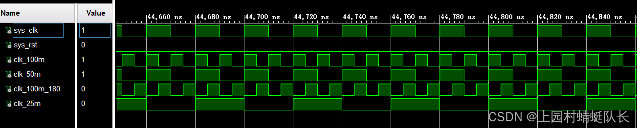
As can be seen from this figure, it fully meets our output requirements.